1
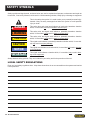
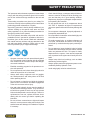
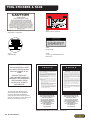
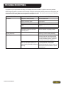
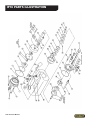
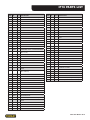
IP16
HYDRAULIC
INTENSIFIER
Safety, Operation and Maintenance
USER MANUAL
© 2011 Stanley Black & Decker, Inc.
New Britain, CT 06053
U.S.A.
10413 3/2011 Ver. 2
TABLE OF CONTENTS
SAFETY SYMBOLS...................................................................................................................................................4
SAFETY PRECAUTIONS...........................................................................................................................................5
TOOL STICKERS & TAGS.........................................................................................................................................6
HOSE TYPES.............................................................................................................................................................7
HOSE RECOMMENDATIONS...................................................................................................................................8
Figure 1. Typical Hose Connections........................................................................................................8
HTMA REQUIREMENTS............................................................................................................................................9
OPERATION.............................................................................................................................................................10
TOOL PROTECTION & CARE................................................................................................................................. 11
TROUBLESHOOTING.............................................................................................................................................12
SPECIFICATIONS....................................................................................................................................................13
IP16 PARTS ILLUSTRATION...................................................................................................................................14
IP16 PARTS LIST.....................................................................................................................................................15
IMPORTANT
To fill out a Product Warranty Recording form, and for information on your warranty,
visit Stanleyhydraulic.com and select the Warranty tab.
(Note: the warranty recording form must be submitted to validate the warranty).
SERVICING THE STANLEY HYDRAULIC INTENSIFIER. This manual contains safety, operation, and routine
maintenance instructions. Stanley Hydraulic Tools recommends that servicing of hydraulic tools, other than routine
maintenance, must be performed by an authorized and certified dealer. Please read the following warning.
WARNING
SERIOUS INJURY OR DEATH COULD RESULT FROM THE IMPROPER
REPAIR OR SERVICE OF THIS TOOL.
REPAIRS AND / OR SERVICE TO THIS TOOL MUST ONLY BE DONE BY AN
AUTHORIZED AND CERTIFIED DEALER.
For the nearest authorized and certified dealer, call Stanley Hydraulic Tools at the number listed on the back of this
manual and ask for a Customer Service Representative.
IP16 User Manual ◄ 3
SAFETY SYMBOLS
Safety symbols and signal words, as shown below, are used to emphasize all operator, maintenance and repair actions which, if not strictly followed, could result in a life-threatening situation, bodily injury or damage to equipment.
This is the safety alert symbol. It is used to alert you to potential personal injury
hazards. Obey all safety messages that follow this symbol to avoid possible
injury or death.
DANGER
This safety alert and signal word indicate an imminently hazardous situation
which, if not avoided, will result in death or serious injury.
WARNING
This safety alert and signal word indicate a potentially hazardous situation
which, if not avoided, could result in death or serious injury.
CAUTION
This safety alert and signal word indicate a potentially hazardous situation
which, if not avoided, could result in death or serious injury.
CAUTION
This signal word indicates a potentially hazardous situation which, if not avoided, may result in property damage.
NOTICE
This signal word indicates a situation which, if not avoided, will result in damage
to the equipment.
IMPORTANT
This signal word indicates a situation which, if not avoided, may result in damage to the equipment.
Always observe safety symbols. They are included for your safety and for the protection of the tool.
LOCAL SAFETY REGULATIONS
Enter any local safety regulations here. Keep these instructions in an area accessible to the operator and maintenance personnel.
4 ► IP16 User Manual
SAFETY PRECAUTIONS
Tool operators and maintenance personnel must always
comply with the safety precautions given in this manual
and on the stickers and tags attached to the tool and
hose.
These safety precautions are given for your safety. Review them carefully before operating the tool and before
performing general maintenance or repairs.
Supervising personnel should develop additional precautions relating to the specific work area and local
safety regulations. If so, place the added precautions in
the space provided in this manual.
The IP16 Hydraulic Intensifier will provide safe and dependable service if operated in accordance with the instructions given in this manual. Read and understand
this manual and any stickers and tags attached to the
tool and hoses before operation. Failure to do so could
result in personal injury or equipment damage.
•
Operator must start in a work area without bystanders. The operator must be familiar with all prohibited
work areas such as excessive slopes and dangerous terrain conditions.
•
Establish a training program for all operators to ensure safe operation.
•
Do not operate the tool unless thoroughly trained or
under the supervision of an instructor.
•
Always wear safety equipment such as goggles,
ear, head protection, and safety shoes at all times
when operating the tool.
•
Do not inspect or clean the tool while the hydraulic
power source is connected. Accidental engagement
of the tool can cause serious injury.
•
Inlet and outlet hydraulic hoses must be capable of
10,000/700 bar working pressure. They must be fitted with hose guards at each end to help prevent
kinks and sharp bends near the fittings. If these requirements are not met, replace the hoses immediately with the correct type before operating the
intensifier.
•
Be sure all hose connections are tight and inspect
hoses for correct pressure rating and for kinks, cuts
swelled areas and damage from abrasion. Replace
if necessary.
•
Check that all fittings, connectors and quick disconnects are rated at 10,000 psi/700 bar working pressure and that they are in good working condition.
Replace any improper or damaged components before operating the intensifier.
•
Do not operate the tool at oil temperatures above
140 °F/60 °C. Operation at higher oil temperatures
can cause operator discomfort and may damage the
tool.
•
Do not operate a damaged, improperly adjusted, or
incompletely assembled tool.
•
Do not operate the intensifier unless both high-pressure hoses are connected.
•
To avoid personal injury or equipment damage, all
tool repair, maintenance and service must only be
performed by authorized and properly trained personnel.
•
Do not attempt to locate hydraulic leaks by feeling
around hoses and fittings with bare hands. Pinhole
leaks can penetrate the skin. To inspect for leaks,
depressurize the system, clean around suspected
area, repressurize the system and visually check for
leaks.
•
Always keep critical tool markings, such as labels
and warning stickers legible.
•
Always replace parts with replacement parts recommended by Stanley Hydraulic Tools.
•
Avoid using tightly curled or twisted hoses.
IP16 User Manual ◄ 5
TOOL STICKERS & TAGS
DANGER
Failure to use hydraulic hose labeled and certified
as non-conductive when using hydraulic tools on
or near electric lines may result in death or
serious injury.
For proper and safe operation read owners manual
and mwke sure that you have been properly
ELECTROCUTION
HAZARD
trained in correct procedures required for work
on or around electric lines.
12412
Warning Sticker—Electrical
03783
GPM Sticker 3–9 2000 PSI
12891
Danger Sticker
10146
IP16 Name Tag
10515
Caution Tag—“SHIPPED W/O OIL”
(Not shown)
NOTE:
THE INFORMATION LISTED
ON THE STICKERS SHOWN,
MUST BE LEGIBLE AT ALL
TIMES.
REPLACE DECALS IF
THEY BECOME WORN OR
DAMAGED. REPLACEMENTS
ARE AVAILABLE FROM
YOUR LOCAL STANLEY
DISTRIBUTOR.
The safety tag (p/n 15875) at right is
attached to the tool when shipped from
the factory. Read and understand the
safety instructions listed on this tag before
removal. We suggest you retain this tag and
attach it to the tool when not in use.
D A N G E R
1.
FAILURE TO USE HYDRAULIC HOSE LABELED AND CERTIFIED AS NON-CONDUCTIVE WHEN USING HYDRAULIC
TOOLS ON OR NEAR ELECTRICAL LINES MAY RESULT IN
DEATH OR SERIOUS INJURY.
BEFORE USING HOSE LABELED AND CERTIFIED AS NONCONDUCTIVE ON OR NEAR ELECTRIC LINES BE SURE THE
HOSE IS MAINTAINED AS NON-CONDUCTIVE. THE HOSE
SHOULD BE REGULARLY TESTED FOR ELECTRIC CURRENT LEAKAGE IN ACCORDANCE WITH YOUR SAFETY
DEPARTMENT INSTRUCTIONS.
2.
A HYDRAULIC LEAK OR BURST MAY CAUSE OIL INJECTION INTO THE BODY OR CAUSE OTHER SEVERE
PERSONAL INJURY.
A.
DO NOT EXCEED SPECIFIED FLOW AND PRESSURE
FOR THIS TOOL. EXCESS FLOW OR PRESSURE MAY
CAUSE A LEAK OR BURST.
B.
DO NOT EXCEED RATED WORKING PRESSURE OF
HYDRAULIC HOSE USED WITH THIS TOOL. EXCESS
PRESSURE MAY CAUSE A LEAK OR BURST.
C. CHECK TOOL HOSE COUPLERS AND CONNECTORS
DAILY FOR LEAKS. DO NOT FEEL FOR LEAKS WITH
YOUR HANDS. CONTACT WITH A LEAK MAY RESULT
IN SEVERE PERSONAL INJURY.
D A N G E R
D. DO NOT LIFT OR CARRY TOOL BY THE HOSES. DO
NOT ABUSE HOSE. DO NOT USE KINKED, TORN OR
DAMAGED HOSE.
3.
MAKE SURE HYDRAULIC HOSES ARE PROPERLY CONNECTED TO THE TOOL BEFORE PRESSURING SYSTEM.
SYSTEM PRESSURE HOSE MUST ALWAYS BE CONNECTED TO TOOL “IN” PORT. SYSTEM RETURN HOSE
MUST ALWAYS BE CONNECTED TO TOOL “OUT” PORT.
REVERSING CONNECTIONS MAY CAUSE REVERSE
TOOL OPERATION WHICH CAN RESULT IN SEVERE
PERSONAL INJURY.
4.
DO NOT CONNECT OPEN-CENTER TOOLS TO CLOSEDCENTER HYDRAULIC SYSTEMS. THIS MAY RESULT IN
LOSS OF OTHER HYDRAULIC FUNCTIONS POWERED BY
THE SAME SYSTEM AND/OR SEVERE PERSONAL INJURY.
5.
BYSTANDERS MAY BE INJURED IN YOUR WORK AREA.
KEEP BYSTANDERS CLEAR OF YOUR WORK AREA.
6.
WEAR HEARING, EYE, FOOT, HAND AND HEAD PROTECTION.
7.
TO AVOID PERSONAL INJURY OR EQUIPMENT DAMAGE,
ALL TOOL REPAIR MAINTENANCE AND SERVICE MUST
ONLY BE PERFORMED BY AUTHORIZED AND PROPERLY
TRAINED PERSONNEL.
I M P O R T A N T
I M P O R T A N T
READ OPERATION MANUAL AND
SAFETY INSTRUCTIONS FOR THIS
TOOL BEFORE USING IT.
READ OPERATION MANUAL AND
SAFETY INSTRUCTIONS FOR THIS
TOOL BEFORE USING IT.
USE ONLY PARTS AND REPAIR
PROCEDURES APPROVED BY
STANLEY AND DESCRIBED IN THE
OPERATION MANUAL.
USE ONLY PARTS AND REPAIR
PROCEDURES APPROVED BY
STANLEY AND DESCRIBED IN THE
OPERATION MANUAL.
TAG TO BE REMOVED ONLY BY
TOOL OPERATOR.
TAG TO BE REMOVED ONLY BY
TOOL OPERATOR.
SEE OTHER SIDE
SEE OTHER SIDE
SAFETY TAG P/N 15875 (Shown smaller then actual size)
6 ► IP16 User Manual
HOSE TYPES
The rated working pressure of the hydraulic hose must be equal to or higher than the relief valve setting on the hydraulic system. There are three types of hydraulic hose that meet this requirement and are authorized for use with
Stanley Hydraulic Tools. They are:
Certified non-conductive — constructed of thermoplastic or synthetic rubber inner tube, synthetic fiber braid
reinforcement, and weather resistant thermoplastic or synthetic rubber cover. Hose labeled certified nonconductive is the only hose authorized for use near electrical conductors.
Wire-braided (conductive) — constructed of synthetic rubber inner tube, single or double wire braid reinforcement, and weather resistant synthetic rubber cover. This hose is conductive and must never be used near
electrical conductors.
Fabric-braided (not certified or labeled non-conductive) — constructed of thermoplastic or synthetic rubber inner tube, synthetic fiber braid reinforcement, and weather resistant thermoplastic or synthetic rubber cover. This
hose is not certified non-conductive and must never be used near electrical conductors.
hOSE SAFETY TAGS
To help ensure your safety, the following DANGER tags are attached to all hose purchased from Stanley Hydraulic
Tools. DO NOT REMOVE THESE TAGS.
If the information on a tag is illegible because of wear or damage, replace the tag immediately. A new tag may be
obtained from your Stanley Distributor.
D A N G E R
D A N G E R
1.
FAILURE TO USE HYDRAULIC HOSE LABELED AND CERTIFIED AS NON-CONDUCTIVE
WHEN USING HYDRAULIC TOOLS ON OR NEAR ELECTRIC LINES MAY RESULT IN
DEATH OR SERIOUS INJURY.
FOR PROPER AND SAFE OPERATION MAKE SURE THAT YOU HAVE BEEN PROPERLY TRAINED IN CORRECT PROCEDURES REQUIRED FOR WORK ON OR AROUND
ELECTRIC LINES.
2.
BEFORE USING HYDRAULIC HOSE LABELED AND CERTIFIED AS NON-CONDUCTIVE
ON OR NEAR ELECTRIC LINES. WIPE THE ENTIRE LENGTH OF THE HOSE AND FITTING WITH A CLEAN DRY ABSORBENT CLOTH TO REMOVE DIRT AND MOISTURE AND
TEST HOSE FOR MAXIMUM ALLOWABLE CURRENT LEAKAGE IN ACCORDANCE WITH
SAFETY DEPARTMENT INSTRUCTIONS.
3.
DO NOT EXCEED HOSE WORKING PRESSURE OR ABUSE HOSE. IMPROPER USE
OR HANDLING OF HOSE COULD RESULT IN BURST OR OTHER HOSE FAILURE.
KEEP HOSE AS FAR AWAY AS POSSIBLE FROM BODY AND DO NOT PERMIT DIRECT
CONTACT DURING USE. CONTACT AT THE BURST CAN CAUSE BODILY INJECTION
AND SEVERE PERSONAL INJURY.
4.
HANDLE AND ROUTE HOSE CAREFULLY TO AVOID KINKING, ABRASION, CUTTING, OR
CONTACT WITH HIGH TEMPERATURE SURFACES. DO NOT USE IF KINKED. DO NOT
USE HOSE TO PULL OR LIFT TOOLS, POWER UNITS, ETC.
5.
CHECK ENTIRE HOSE FOR CUTS CRACKS LEAKS ABRASIONS, BULGES, OR DAMAGE TO COUPLINGS IF ANY OF THESE CONDITIONS EXIST, REPLACE THE HOSE
IMMEDIATELY. NEVER USE TAPE OR ANY DEVICE TO ATTEMPT TO MEND THE HOSE.
6.
AFTER EACH USE STORE IN A CLEAN DRY AREA.
SEE OTHER SIDE
SIDE 1
SEE OTHER SIDE
(Shown smaller than actual size)
DO NOT REMOVE THIS TAG
DO NOT REMOVE THIS TAG
The tag shown below is attached to “certified non-conductive” hose
SIDE 2
D A N G E R
D A N G E R
1.
DO NOT USE THIS HYDRAULIC HOSE ON OR NEAR ELECTRIC LINES. THIS HOSE IS
NOT LABELED OR CERTIFIED AS NON-CONDUCTIVE. USING THIS HOSE ON OR NEAR
ELECTRICAL LINES MAY RESULT IN DEATH OR SERIOUS INJURY.
5.
CHECK ENTIRE HOSE FOR CUTS CRACKS LEAKS ABRASIONS, BULGES, OR DAMAGE TO
COUPLINGS IF ANY OF THESE CONDITIONS EXIST, REPLACE THE HOSE IMMEDIATELY.
NEVER USE TAPE OR ANY DEVICE TO ATTEMPT TO MEND THE HOSE.
2.
FOR PROPER AND SAFE OPERATION MAKE SURE THAT YOU HAVE BEEN PROPERLY
TRAINED IN CORRECT PROCEDURES REQUIRED FOR WORK ON OR AROUND ELECTRIC LINES.
6.
AFTER EACH USE STORE IN A CLEAN DRY AREA.
3.
DO NOT EXCEED HOSE WORKING PRESSURE OR ABUSE HOSE. IMPROPER USE OR
HANDLING OF HOSE COULD RESULT IN BURST OR OTHER HOSE FAILURE. KEEP HOSE
AS FAR AWAY AS POSSIBLE FROM BODY AND DO NOT PERMIT DIRECT CONTACT
DURING USE. CONTACT AT THE BURST CAN CAUSE BODILY INJECTION AND SEVERE
PERSONAL INJURY.
4.
HANDLE AND ROUTE HOSE CAREFULLY TO AVOID KINKING, CUTTING, OR CONTACT
WITH HIGH TEMPERATURE SURFACES. DO NOT USE IF KINKED. DO NOT USE HOSE TO
PULL OR LIFT TOOLS, POWER UNITS, ETC.
DO NOT REMOVE THIS TAG
DO NOT REMOVE THIS TAG
The tag shown below is attached to “conductive” hose.
SEE OTHER SIDE
SEE OTHER SIDE
SIDE 1
SIDE 2
(Shown smaller than actual size)
IP16 User Manual ◄ 7
8 ► IP16 User Manual
All hydraulic hose must meet or exceed
specifications as set forth by SAE J517.
All hydraulic hose must have at least a rated
minimum working pressure equal to the maximum hydraulic system relief valve setting.
This chart is intended to be used for hydraulic
tool applications only based on Stanley Hydraulic Tools tool operating requirements and
should not be used for any other applications.
The chart to the right shows recommended
minimum hose diameters for various hose
lengths based on gallons per minute (gpm)/
liters per minute (lpm). These recommendations are intended to keep return line pressure
(back pressure) to a minimum acceptable level to ensure maximum tool performance.
Tool to Hydraulic Circuit Hose
Recommendations
15-34
MM
Inside Diameter
INCH
USE
(Press/Return)
PSI
up to 10
up to 3
3/8
10
Both
2250
49-60
13-16
FLOW >>>
RETURN
<<< FLOW
PRESSURE
26-100
up to 25
100-200
51-100
up to 50
100-300
51-100
up to 50
26-100
up to 25
8-30
up to 8
30-60
15-30
up to 15
30-90
15-30
up to 15
7.5-30
up to 7.5
Figure 1. Typical Hose Connections
49-60
13-16
38-49
10-13
38-49
19-40
5-10.5
10-13
19-40
5-10.5
38-49
19-40
5-10.5
10-13
15-23
15-23
4-6
3/8
10
19
19
25.4
3/4
1
16
5/8
3/4
19
25.4
1
19
3/4
3/4
16
16
19
5/8
16
5/8
3/4
5/8
16
13
13
5/8
1/2
1/2
Both
Return
Pressure
Return
Pressure
Return
Pressure
Return
Pressure
Both
Return
Pressure
Both
Both
Both
2500
2500
2500
2500
2500
2500
2500
2500
2500
2500
2500
2500
2500
2500
2500
175
175
175
175
175
175
175
175
175
175
175
175
175
175
175
155
BAR
Min. Working Pressure
Certified Non-Conductive Hose - Fiber Braid - for Utility Bucket Trucks
METERS
Hose Lengths
FEET
Conductive Hose - Wire Braid or Fiber Braid -DO NOT USE NEAR ELECTRICAL CONDUCTORS
4-6
4-9
LPM
Oil Flow
GPM
HOSE RECOMMENDATIONS
HTMA REQUIREMENTS
TOOL CATEGORY
HYDRAULIC SYSTEM
REQUIREMENTS
TYPE I
TYPE II
TYPE III
TYPE RR
Flow Rate
4–6 gpm
(15–23 lpm)
7–9 gpm
(26–34 lpm)
11–13 gpm
(42–49 lpm)
9–10.5 gpm
(34–40 lpm)
Tool Operating Pressure
(At the power supply outlet)
2000 psi
(145–155 bar)
2000 psi
(138 bar)
2000 psi
(138 bar)
2000 psi
(138 bar)
System relief valve setting
(At the power supply outlet)
2100–2250 psi
(145–155 bar)
2100–2250 psi
(145–155 bar)
2100–2250 psi
(145–155 bar)
2200–2300 psi
(145–155 bar)
Maximum back pressure
(At tool end of the return hose)
250 psi
(17 bar)
250 psi
(17 bar)
250 psi
(17 bar)
250 psi
(17 bar)
Measured at a max. fluid viscosity of:
(At min. operating temperature)
400 ssu*
(82 centistokes)
400 ssu*
400 ssu*
400 ssu*
(82 centistokes) (82 centistokes) (82 centistokes)
Temperature
Sufficient heat rejection capacity
to limit max. fluid temperature to:
(At max. expected ambient temperature)
140 °F
(60 °C)
140 °F
(60 °C)
140 °F
(60 °C)
140 °F
(60 °C)
Min. cooling capacity
at a temperature difference of
between ambient and fluid temps
3 hp
(2.24 kW)
40 °F
(22 °C)
5 hp
(3.73 kW)
40 °F
(22 °C)
7 hp
(4.47 kW)
40 °F
(22 °C)
6 hp
(5.22 kW)
40 °F
(22 °C)
NOTE:
Do not operate the tool at oil temperatures above 140 °F (60 °C). Operation at higher temperatures can cause operator
discomfort at the tool.
Filter
Min. full-flow filtration
Sized for flow of at least:
(For cold temp. start-up and max. dirt-holding
capacity)
25 microns
30 gpm
(114 lpm)
25 microns
30 gpm
(114 lpm)
25 microns
30 gpm
(114 lpm)
25 microns
30 gpm
(114 lpm)
Hydraulic fluid
100–400 ssu*
100–400 ssu*
100–400 ssu*
100–400 ssu*
Petroleum based
(Premium grade, anti-wear, non-conductive)
Viscosity
(At min. and max. operating temps)
(20–82 centistokes)
NOTE:
When choosing hydraulic fluid, the expected oil temperature extremes that will be experienced in service determine
the most suitable temperature viscosity characteristics. Hydraulic fluids with a viscosity index over 140 will meet the
requirements over a wide range of operating temperatures.
*SSU = Saybolt Seconds Universal
IP16 User Manual ◄ 9
OPERATION
PRE-OPERATION PROCEDURES
Fill reservoir
IMPORTANT
Mil-H 5606 Hydraulic Oil must not be used in the
reservoir of the intensifier.
1. Remove the vent plug from the top of the intensifier.
Fill with clean hydraulic oil filtered to 10 microns or
less. Fill to top of high pressure pump as viewed
from the filler hole.
NOTE:
High-pressure couplings must be used for the highpressure connections at the output side of the intensifier.
4. Connect the tool to be used (stretcher, cutter, etc,)
to the unit. Refer to the applicable Operation Manual
for detailed connection procedures.
5. Move the hydraulic circuit control valve to the ON
position to operate the intensifier.
NOTE:
If uncoupled hoses are left in the sun, pressure increase within the hoses may make them difficult to
connect. When possible, connect the free ends of
operating hoses together.
Tool operation
IMPORTANT
Do not fill to top of hole. An air space is required for
hydraulic oil expansion as oil temperature increases.
2. An over-full reservoir will cause oil leakage from the
vent plug as the oil heats. If this condition occurs,
remove the vent plug and lower oil level to the point
specified.
Check Hydraulic Power Source
1. Using a calibrated flowmeter and pressure gauge,
check that the hydraulic power source develops a
flow of 4–10 gpm/15–38 lpm at 1000–2000 psi/70–
140 bar.
2. Make certain the hydraulic power source is equipped
with a relief valve set to open at 2100–2300 psi/145–
159 bar maximum.
3. Check that the hydraulic circuit matches the tool for
open-center (OC) operation.
Connect hoses
1. Remove the thread protectors and valve caps from
the intensifier.
2. Wipe all hose couplers with a clean lint-free cloth
before making hose connections.
3. Connect hydraulic lines from the parent circuit to the
intensifier inlet fitting. Make certain the “P” (pressure) and “T” (tank) hoses are connected to their
respective ports. If incorrectly connected, high pressure output will not be obtained.
10 ► IP16 User Manual
1. Observe all safety precautions
2. Activate the parent circuit to energize the intensifier.
Pressure should now be available at the pressure
port of the tool. At this time, the control valve and
tool are ready for operation.
3. Verify operating pressure requirements of tool being
used and adjust intensifier relief valve as required.
NOTE:
Higher flows and/or high back-pressure will increase the output pressure. Adjust the output relief
valve under the flow and operating conditions the
tool will be used under.
The load valve locks the tool outlet and is to be used
to hold the tool in a fixed position. The pressure gauge
reads on the tool side of the valve to monitor the load.
COLD WEATHER OPERATION
If the tool is to be used during cold weather, preheat the
hydraulic fluid at low engine speed. When using the normally recommended fluids, fluid temperature should be
at or above 50 °F/10 °C (400 ssu/82 centistokes) before
use.
TOOL PROTECTION & CARE
NOTICE
In addition to the Safety Precautions found in
this manual, observe the following for equipment
protection and care.
•
Make sure all couplers are wiped clean before connection.
•
The hydraulic circuit control valve must be in the
OFF position when coupling or uncoupling hydraulic tools. Failure to do so may result in damage to
the quick couplers and cause overheating of the hydraulic system.
•
Always store the tool in a clean dry space, safe from
damage or pilferage.
•
Always replace hoses, couplings and other parts
with replacement parts recommended by Stanley
Hydraulic Tools. Supply hoses to the intensifier must
have a minimum working pressure rating of 2500
psi/172 bar. Supply hoses from the intensifier to the
tool couplings and other high-pressure parts, must
have a minimum working pressure rating of 10,000
psi/700 bar.
•
All hoses must have an oil resistant inner surface
and an abrasion resistant outer surface. Whenever
near electrical conductors, use clean hoses labeled
and certified non-conductive.
•
Never allow the working pressure of the intensifier
or tool to exceed 10,000 psi/690 bar.
•
Always keep critical tool markings, such as warning
stickers and tags legible.
•
Make sure that the compression tool, cutter, etc. to
be operated is rated at 10,000 psi/690 bar. If other
than 10,000 psi/700 bar, the intensifier relief valve
must be adjusted to the pressure for the tool being
operated.
•
Operate the intensifier within its rated capacity.
•
Do not use the intensifier for applications for which it
was not designed.
•
Tool repair should be performed by experienced
personnel only.
•
Never connect or disconnect couplers or port connections with hydraulic pressure in the hose.
•
Always check high-pressure couplers for leaks and
damage before operating the system at maximum
rated pressure.
•
When the intensifier is not in use, attach thread protectors and install valve caps.
IP16 User Manual ◄ 11
TROUBLESHOOTING
If symptoms of poor performance develop, the following chart can be used as a guide to correct the problem.
When diagnosing faults in operation of the intensifier, always check that the hydraulic power source is supplying the
correct hydraulic flow and pressure to the intensifier as listed in the table. Use a flow meter known to be accurate.
Check the flow with the hydraulic fluid temperature at least 80 °F/27 °C.
PROBLEM
No output.
Oil mist from center of motor
housing assembly.
CAUSE
Couplers or hoses blocked.
Remove obstruction.
Input pressure and return line
hoses reversed at ports.
Be sure hoses are connected to the
proper ports.
No oil in reservoir.
Fill reservoir to proper level.
High-pressure relief valve stuck
open.
Test and adjust as specified in Service
section.
Motor to pump hose leaking.
Remove and replace hose.
Intensifier turned over with vent
assembly down.
Return intensifier to upright position.
Rear drive shaft seal bad.
Replace shaft seal located behind shaft
bushing in motor housing assembly.
Oil leaking from vent assembly. Oil reservoir over filled.
Defective shaft seal. Seal is located
in the oil seal plate between the
motor housing assembly and pump
housing.
12 ► IP16 User Manual
SOLUTION
Reduce oil level to the top of the highpressure pump as viewed through the
vent assembly port while the intensifier
is in the horizontal position. (Reservoir
must have room for oil expansion.)
Turn off intensifier. Remove vent
assembly and turn on intensifier.
Operate compression tool or cutter. If oil
reservoir fills up and overflows, replace
the shaft seal.
SPECIFICATIONS
Output Pressure.............................................................................................................................10,000 psi/700 Bar
Input Pressure......................................................................................................................... Up to 2500 psi/176 Bar
Flow Range................................................................................................................................ 4–10 gpm/15–38 lpm
Porting.............................................................................................................................................................3/8 NPT
Connect Size and Type.................................................................................................................................. 3/8 NPT
Weight.................................................................................................................................................29.6 lbs/13.4 kg
Length (with couplers).............................................................................................................................. 18 in./46 cm
Width.......................................................................................................................................................... 8 in./20 cm
Height......................................................................................................................................................... 9 in./23 cm
IP16 User Manual ◄ 13
IP16 PARTS ILLUSTRATION
14 ► IP16 User Manual
IP16 PARTS LIST
ITEM
1
PART
NO.
QTY
DESCRIPTION
ITEM
PART
NO.
QTY
DESCRIPTION
09853
1
MOTOR ASSY (INCL ITEMS 1–15)
40
09884
1
O-RING 7/32 × 11/32 × 1/18 *
09868
1
MOTOR HOUSING (INCL ITEM 2)
41
09887
1
O-RING URETHANE *
2
05207
1
BUSHING
42
09870
1
HOSE
3
13996
2
O-RING 1/2 × 11/18 × 3/32 *
43
09898
1
MALE CONNECTOR
4
01257
1
O-ring 3-1/2 × 3-5/8 × 1/16 *
44
00149
1
O-RING 3-3/4 × 3-3/8 × 1/16 *
5
05641
1
O-ring 2-3/8 × 2-1/2 × 1/16 *
45
09883
6
CAPSCREW 10-32 × 3 IN SOCKET HEAD
6
09594
1
Gerotor
46
09857
1
END PLATE ASSY
7
09839
1
Gerotor bushing
47
09842
1
VALVE CAP
48
00012
1
O-RING *
09862
1
HIGH-PRESSURE UNLOADING VALVE
ASSY
49
09891
1
SETSCREW
50
09843
1
VALVE BODY
51
09837
1
PINTAL UNLOADING VALVE
52
09309
1
SPRING
8
09844
1
Oil seal plate
9
09895
1
Gerotor
10
09850
1
Pump housing
11
09901
6
Flange nut
12
09900
1
Dowel pin
13
09867
1
Drive pin
14
09838
1
Drive shaft
15
09883
6
Capscrew 10-24 × 3 in Socket head
09861
1
Low pressure valve assy
(incl 15–18)
09841
1
Low-pressure valve
16
53
09834
1
ADJUSTING PLUG
54
09835
1
SEAL WASHER *
55
05337
1
HIGH-PRESSURE NIPPLE
56
05148
1
HEX NIPPLE
57
05338
1
HIGH-PRESSURE COUPLER
17
02436
1
Check ball
18
09893
1
Spring
58
09865
1
VENT ASSY (INCL O-RING)
11720
1
SIGHT GLASS
19
09892
1
Setscrew
59
20
09898
1
Male connector
60
03364
1
O-RING .414 × .558 × .072
21
00936
2
Adaptor fitting
61
03783
1
GPM/PRESSURE STICKER
22
09886
3
Capscrew, 10-32 × 3/8 in socket
head
62
12412
1
WARNING STICKER
Wobble plate housing
(incl item 23)
63
12891
1
DANGER STICKER
64
10515
1
CAUTION TAG, UNIT SHIPPED W/O OIL
65
10146
1
NAMEPLATE STICKER
23
09871
1
24
05207
1
Bushing
25
09882
2
Capscrew 10-32 × 1 in socket head
26
09877
2
THRUST WASHER
27
09878
1
THRUST BEARING
28
01851
1
ROLL PIN 1/8 × 1 IN
29
09845
1
WOBBLE PLATE
30
09879
1
THRUST WASHER
31
08148
1
THRUST BEARING
32
09840
1
THRUST WASHER
33
09881
1
BEARING
34
35
00077
1
RETAINING RING
15283
1
PUMP ASSY (INCL ITEMS 34–38)
08253
4
CAPSCREW 1/4-20 × 1-1/2 IN SOCKET
HEAD
36
09847
1
PISTON BLOCK
37
09836
4
PISTON
38
09866
1
CHECK BALL BLOCK ASSY
39
09869
1
MANIFOLD ASSY
66
11718
1
PUMP CASE
—
06345
2
PLASTIC PLUG, SAE8 (NOT SHOWN)
—
14785
1
SEAL KIT (* INDICATES PART OF KIT)
IP16 User Manual ◄ 15
Stanley Hydraulic Tools
3810 SE Naef Road
Milwaukie, Oregon 97267-5698 USA
(503) 659-5660 / Fax (503) 652-1780
www.stanleyhydraulic.com
IMPORTANT
To fill out a Product Warranty Recording form, and for information on your warranty,
visit Stanleyhydraulic.com and select the Warranty tab.
(Note: the warranty recording form must be submitted to validate the warranty).