1
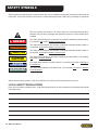
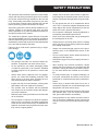
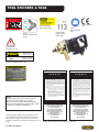
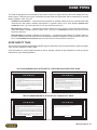
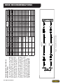
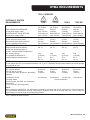
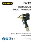
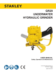
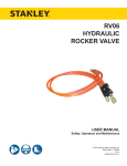
IW16
HYDRAULIC
IMPACT WRENCH
Safety, Operation and Maintenance
USER MANUAL
© 2010 Stanley Black & Decker, Inc.
New Britain, CT 06053
U.S.A.
66174 12/2010 Ver 5
CERTIFICATE OF
DECLARATION
OFCONFORMITY
CONFORMITY
DECLARATION OF CONFORMITY
ÜBEREINSTIMMUNGS-ERkLARUNG
DECLARATION DE CONFORMITE CEE
DECLARACION DE CONFORMIDAD
DICHIARAZIONE DI CONFORMITA
Hydraulic Tools
______________________________________________________________________
I, the undersigned:
Ich, der Unterzeichnende:
Je soussigné:
El abajo firmante:
lo sottoscritto:
Weisbeck, Andy
Surname and First names/Familiennname und Vornamen/Nom et prénom/Nombre y apellido/Cognome e nome
hereby declare that the equipment specified hereunder:
bestätige hiermit, daß erklaren Produkt genannten Werk oder Gerät:
déclare que l’équipement visé ci-dessous:
Por la presente declaro que el equipo se especifica a continuación:
Dichiaro che le apparecchiature specificate di seguito:
Hydraulic Hand Held Impact Wrench
1.
Category:
Kategorie:
Catégorie:
Categoria:
Categoria:
2.
Make/Marke/Marque/Marca/Marca
3.
Type/Typ/Type/Tipo/Tipo:
4.
Serial number of equipment:
Seriennummer des Geräts:
Numéro de série de l’équipement:
Numero de serie del equipo:
Matricola dell´attrezzatura:
Stanley
IW1615001, IW1635001, IW1615701
All
Has been manufactured in conformity with
Wurde hergestellt in Übereinstimmung mit
Est fabriqué conformément
Ha sido fabricado de acuerdo con
E’ stata costruita in conformitá con
Directive/Standards
Richtlinie/Standards
Directives/Normes
Directriz/Los Normas
Direttiva/Norme
No.
Nr
Numéro
No
n.
Approved body
Prüfung durch
Organisme agréé
Aprobado
Collaudato
EN
EN ISO
EN
Machinery Directive
792-6:1994
3744:2009
28927-2:2009
2006/42/EC:2006
Self
Self
Self
Self
5.
Special Provisions:
None
Spezielle Bestimmungen:
Dispositions particulières:
Provisiones especiales:
Disposizioni speciali:
6.
Representative in the Union: Patrick Vervier, Stanley Dubuis 17-19, rue Jules Berthonneau-BP 3406 41034 Blois Cedex, France.
Vertreter in der Union/Représentant dans l’union/Representante en la Union/Rappresentante presso l’Unione
Done at/Ort/Fait à/Dado en/Fatto a Stanley Hydraulic Tools, Milwaukie, Oregon USA
Signature/Unterschrift/Signature/Firma/Firma
Position/Position/Fonction/Cargo/Posizione
12/19/2010
2 ► IW16 User Manual
Engineering Manager
Date/Datum/le/Fecha/Data
12-22-10
TABLE OF CONTENTS
DECLARATION OF CONFORMITY...........................................................................................................................2
SAFETY SYMBOLS...................................................................................................................................................4
SAFETY PRECAUTIONS...........................................................................................................................................5
TOOL STICKERS & TAGS.........................................................................................................................................6
HOSE TYPES.............................................................................................................................................................7
HOSE RECOMMENDATIONS...................................................................................................................................8
Figure 1. Typical Hose Connections........................................................................................................8
HTMA REQUIREMENTS............................................................................................................................................9
WRENCH TORQUE INFORMATION.......................................................................................................................10
WRENCH OPERATION........................................................................................................................................... 11
Equipment protection & care.....................................................................................................................12
TROUBLESHOOTING.............................................................................................................................................13
SPECIFICATIONS....................................................................................................................................................14
Accessories.......................................................................................................................................................15
IW16 PARTS ILLUSTRATION..................................................................................................................................16
iw16 EXTENSION HANDLE illustration.........................................................................................................17
IW16 PARTS LIST....................................................................................................................................................18
IMPORTANT
To fill out a Product Warranty Recording form, and for information on your warranty,
visit Stanleyhydraulic.com and select the Warranty tab.
(Note: the warranty recording form must be submitted to validate the warranty).
SERVICING THE STANLEY HYDRAULIC IMPACT WRENCH. This manual contains safety, operation, and routine
maintenance instructions. Stanley Hydraulic Tools recommends that servicing of hydraulic tools, other than routine
maintenance, must be performed by an authorized and certified dealer. Please read the following warning.
WARNING
SERIOUS INJURY OR DEATH COULD RESULT FROM THE IMPROPER REPAIR OR
SERVICE OF THIS TOOL.
REPAIRS AND / OR SERVICE TO THIS TOOL MUST ONLY BE DONE BY AN
AUTHORIZED AND CERTIFIED DEALER.
For the nearest authorized and certified dealer, call Stanley Hydraulic Tools at the number listed on the back of this
manual and ask for a Customer Service Representative.
IW16 User Manual ◄ 3
HEADER SYMBOLS
SAFETY
A
Safety symbols and signal words, as shown below, are used to emphasize all operator, maintenance and repair actions which, if not strictly followed, could result in a life-threatening situation, bodily injury or damage to equipment.
This is the safety alert symbol. It is used to alert you to potential personal injury
hazards. Obey all safety messages that follow this symbol to avoid possible injury
or death.
DANGER
This safety alert and signal word indicate an imminently hazardous situation which,
if not avoided, will result in death or serious injury.
WARNING
This safety alert and signal word indicate a potentially hazardous situation which, if
not avoided, could result in death or serious injury.
CAUTION
This safety alert and signal word indicate a potentially hazardous situation which, if
not avoided, could result in death or serious injury.
CAUTION
This signal word indicates a potentially hazardous situation which, if not avoided,
may result in property damage.
NOTICE
This signal word indicates a situation which, if not avoided, will result in damage to
the equipment.
IMPORTANT
This signal word indicates a situation which, if not avoided, may result in damage
to the equipment.
Always observe safety symbols. They are included for your safety and for the protection of the tool.
LOCAL SAFETY REGULATIONS
Enter any local safety regulations here. Keep these instructions in an area accessible to the operator and maintenance personnel.
4 ► IW16 User Manual
SAFETY PRECAUTIONS
HEADER A
Tool operators and maintenance personnel must always
comply with the safety precautions given in this manual
and on the stickers and tags attached to the tool and
hose. These safety precautions are given for your safety. Review them carefully before operating the tool and
before performing general maintenance or repairs.
Supervising personnel should develop additional precautions relating to the specific work area and local
safety regulations. If so, place the added precautions in
the space provided in this manual.
The model IW16 Hydraulic Impact Wrench will provide
safe and dependable service if operated in accordance
with the instructions given in this manual. Read and understand this manual and any stickers and tags attached
to the tool and hose before operation.
Failure to do so could result in personal injury or equipment damage.
•
Always connect hoses to the tool hose couplers before energizing the hydraulic power source. Be sure
all hose connections are tight and are in good condition.
•
Do not operate the tool at oil temperatures above
140 °F/60 °C. Operation at higher temperatures can
cause higher than normal temperatures at the tool
which can result in operator discomfort.
•
Do not operate a damaged, improperly adjusted, or
incompletely assembled impact wrench.
•
Never wear loose clothing that can get entangled in
the working parts of the tool.
•
Keep all parts of your body away from the rotating
parts. Long hair or loose clothing can become drawn
into rotating components.
•
Always use accessories that conform to the specifications given in the OPERATION section of this
manual.
•
Do not reverse impact wrench rotation direction by
changing fluid flow direction.
•
Release the trigger if the power supply has been interrupted.
•
When working near electrical conductors, always
assume that all conductors are energized and that
insulation, clothing and hoses can conduct electricity. Use hose labeled and certified as non-conductive.
•
The operator must start in a work area without bystanders. Flying debris can cause serious injury.
•
Do not operate the tool unless thoroughly trained
or under the supervision of an instructor. Establish
a training program for all operators to ensure safe
operation.
•
Always wear safety equipment such as goggles,
gloves, ear, head and breathing protection, and
safety shoes at all times when operating the tool.
Use gloves and aprons when necessary.
•
To avoid personal injury or equipment damage, all
tool repair, maintenance and service must only be
performed by authorized and properly trained personnel.
•
Inspect tool daily for loose fasteners, missing parts
and leakage. Have tool repaired if necessary.
•
•
The operator must be familiar with all prohibited
work areas such as excessive slopes and dangerous terrain conditions.
Serious injury or death could result from a tool or
accessories dropped from an elevated height, also
flying debris can cause serious injury.
•
Warning: Hydraulic fluid under pressure could cause
skin injection injury. If you are injured by hydraulic
fluid, get medical attention immediately.
•
During operation do not contact the impact mechanism, accessories or hardware as they can become
very hot, use your (PPE) Personal Protection Equipment.
•
•
Maintain proper footing and balance at all times and
do not overreach.
Do not inspect or clean the tool while the hydraulic
power source is connected. Accidental engagement
of the tool can cause serious injury. Be observant of
hydraulic and water hose lying about the work area,
they can be a tripping hazard.
IW16 User Manual ◄ 5
HEADER
TOOL
STICKERS
A
& TAGS
DANGER
Failure to use hydraulic hose labeled and certified
as non-conductive when using hydraulic tools on
or near electric lines may result in death or
serious injury.
For proper and safe operation read owners manual
28322 CE DECAL
(CE)
25610 RAILROAD
HELP DESK DECAL
and mwke sure that you have been properly
ELECTROCUTION
HAZARD
trained in correct procedures required for work
on or around electric lines.
12412 DANGER DECAL
52539 SOUND
POWER LEVEL
DECAL (CE)
30136
ROTATION DIRECTION
DECAL
28788
MANUAL DECAL
(CE)
D
30 LPM @ 138 B AR
EHTMA CATEGORY
11207 CIRCUIT
TYPE D DECAL (CE)
Stanley Hydraulic Tools
3810 SE Naef Road
Milwaukie, Oregon USA
Model No.
IW16
26-45 LPM / 7-12 GPM
140 BAR / 2000 PSI
08153 IW16 NAME TAG (US & CE)
D A N G E R
1.
BEFORE USING HOSE LABELED AND CERTIFIED AS NONCONDUCTIVE ON OR NEAR ELECTRIC LINES BE SURE THE
HOSE IS MAINTAINED AS NON-CONDUCTIVE. THE HOSE
SHOULD BE REGULARLY TESTED FOR ELECTRIC CURRENT
LEAKAGE IN ACCORDANCE WITH YOUR SAFETY DEPARTMENT INSTRUCTIONS.
09612 GPM DECAL
2.
NOTE:
THE INFORMATION LISTED ON THE STICKERS
SHOWN, MUST BE LEGIBLE AT ALL TIMES.
REPLACE DECALS IF THEY BECOME WORN OR
DAMAGED. REPLACEMENTS ARE AVAILABLE FROM
YOUR LOCAL STANLEY DISTRIBUTOR.
The safety tag (p/n 15875) at right is attached to the tool
when shipped from the factory. Read and understand the
safety instructions listed on this tag before removal. We
suggest you retain this tag and attach it to the tool when not
in use.
6 ► IW16 User Manual
FAILURE TO USE HYDRAULIC HOSE LABELED AND CERTIFIED AS NON-CONDUCTIVE WHEN USING HYDRAULIC
TOOLS ON OR NEAR ELECTRICAL LINES MAY RESULT IN
DEATH OR SERIOUS INJURY.
A HYDRAULIC LEAK OR BURST MAY CAUSE OIL INJECTION
INTO THE BODY OR CAUSE OTHER SEVERE PERSONAL
INJURY.
A.
DO NOT EXCEED SPECIFIED FLOW AND PRESSURE
FOR THIS TOOL. EXCESS FLOW OR PRESSURE MAY
CAUSE A LEAK OR BURST.
B.
DO NOT EXCEED RATED WORKING PRESSURE OF
HYDRAULIC HOSE USED WITH THIS TOOL. EXCESS
PRESSURE MAY CAUSE A LEAK OR BURST.
C. CHECK TOOL HOSE COUPLERS AND CONNECTORS
DAILY FOR LEAKS. DO NOT FEEL FOR LEAKS WITH
YOUR HANDS. CONTACT WITH A LEAK MAY RESULT
IN SEVERE PERSONAL INJURY.
D A N G E R
D. DO NOT LIFT OR CARRY TOOL BY THE HOSES. DO
NOT ABUSE HOSE. DO NOT USE KINKED, TORN OR
DAMAGED HOSE.
3.
MAKE SURE HYDRAULIC HOSES ARE PROPERLY CONNECTED TO THE TOOL BEFORE PRESSURING SYSTEM.
SYSTEM PRESSURE HOSE MUST ALWAYS BE CONNECTED TO TOOL “IN” PORT. SYSTEM RETURN HOSE
MUST ALWAYS BE CONNECTED TO TOOL “OUT” PORT.
REVERSING CONNECTIONS MAY CAUSE REVERSE
TOOL OPERATION WHICH CAN RESULT IN SEVERE
PERSONAL INJURY.
4.
DO NOT CONNECT OPEN-CENTER TOOLS TO CLOSEDCENTER HYDRAULIC SYSTEMS. THIS MAY RESULT IN
LOSS OF OTHER HYDRAULIC FUNCTIONS POWERED BY
THE SAME SYSTEM AND/OR SEVERE PERSONAL INJURY.
5.
BYSTANDERS MAY BE INJURED IN YOUR WORK AREA.
KEEP BYSTANDERS CLEAR OF YOUR WORK AREA.
6.
WEAR HEARING, EYE, FOOT, HAND AND HEAD PROTECTION.
7.
TO AVOID PERSONAL INJURY OR EQUIPMENT DAMAGE,
ALL TOOL REPAIR MAINTENANCE AND SERVICE MUST
ONLY BE PERFORMED BY AUTHORIZED AND PROPERLY
TRAINED PERSONNEL.
I M P O R T A N T
I M P O R T A N T
READ OPERATION MANUAL AND
SAFETY INSTRUCTIONS FOR THIS
TOOL BEFORE USING IT.
READ OPERATION MANUAL AND
SAFETY INSTRUCTIONS FOR THIS
TOOL BEFORE USING IT.
USE ONLY PARTS AND REPAIR
PROCEDURES APPROVED BY
STANLEY AND DESCRIBED IN THE
OPERATION MANUAL.
USE ONLY PARTS AND REPAIR
PROCEDURES APPROVED BY
STANLEY AND DESCRIBED IN THE
OPERATION MANUAL.
TAG TO BE REMOVED ONLY BY
TOOL OPERATOR.
TAG TO BE REMOVED ONLY BY
TOOL OPERATOR.
SEE OTHER SIDE
SEE OTHER SIDE
SAFETY TAG P/N 15875 (shown smaller then actual size)
HOSE
HEADER
TYPES
B
The rated working pressure of the hydraulic hose must be equal to or higher than the relief valve setting on the hydraulic system. There are three types of hydraulic hose that meet this requirement and are authorized for use with
Stanley Hydraulic Tools. They are:
Certified non-conductive — constructed of thermoplastic or synthetic rubber inner tube, synthetic fiber braid
reinforcement, and weather resistant thermoplastic or synthetic rubber cover. Hose labeled certified nonconductive is the only hose authorized for use near electrical conductors.
Wire-braided (conductive) — constructed of synthetic rubber inner tube, single or double wire braid reinforcement, and weather resistant synthetic rubber cover. This hose is conductive and must never be used near
electrical conductors.
Fabric-braided (not certified or labeled non-conductive) — constructed of thermoplastic or synthetic rubber inner tube, synthetic fiber braid reinforcement, and weather resistant thermoplastic or synthetic rubber cover. This
hose is not certified non-conductive and must never be used near electrical conductors.
hOSE SAFETY TAGS
To help ensure your safety, the following DANGER tags are attached to all hose purchased from Stanley Hydraulic
Tools. DO NOT REMOVE THESE TAGS.
If the information on a tag is illegible because of wear or damage, replace the tag immediately. A new tag may be
obtained from your Stanley Distributor.
D A N G E R
D A N G E R
1.
FAILURE TO USE HYDRAULIC HOSE LABELED AND CERTIFIED AS NON-CONDUCTIVE
WHEN USING HYDRAULIC TOOLS ON OR NEAR ELECTRIC LINES MAY RESULT IN
DEATH OR SERIOUS INJURY.
FOR PROPER AND SAFE OPERATION MAKE SURE THAT YOU HAVE BEEN PROPERLY TRAINED IN CORRECT PROCEDURES REQUIRED FOR WORK ON OR AROUND
ELECTRIC LINES.
2.
BEFORE USING HYDRAULIC HOSE LABELED AND CERTIFIED AS NON-CONDUCTIVE
ON OR NEAR ELECTRIC LINES. WIPE THE ENTIRE LENGTH OF THE HOSE AND FITTING WITH A CLEAN DRY ABSORBENT CLOTH TO REMOVE DIRT AND MOISTURE AND
TEST HOSE FOR MAXIMUM ALLOWABLE CURRENT LEAKAGE IN ACCORDANCE WITH
SAFETY DEPARTMENT INSTRUCTIONS.
3.
DO NOT EXCEED HOSE WORKING PRESSURE OR ABUSE HOSE. IMPROPER USE
OR HANDLING OF HOSE COULD RESULT IN BURST OR OTHER HOSE FAILURE.
KEEP HOSE AS FAR AWAY AS POSSIBLE FROM BODY AND DO NOT PERMIT DIRECT
CONTACT DURING USE. CONTACT AT THE BURST CAN CAUSE BODILY INJECTION
AND SEVERE PERSONAL INJURY.
4.
HANDLE AND ROUTE HOSE CAREFULLY TO AVOID KINKING, ABRASION, CUTTING, OR
CONTACT WITH HIGH TEMPERATURE SURFACES. DO NOT USE IF KINKED. DO NOT
USE HOSE TO PULL OR LIFT TOOLS, POWER UNITS, ETC.
5.
CHECK ENTIRE HOSE FOR CUTS CRACKS LEAKS ABRASIONS, BULGES, OR DAMAGE TO COUPLINGS IF ANY OF THESE CONDITIONS EXIST, REPLACE THE HOSE
IMMEDIATELY. NEVER USE TAPE OR ANY DEVICE TO ATTEMPT TO MEND THE HOSE.
6.
AFTER EACH USE STORE IN A CLEAN DRY AREA.
SEE OTHER SIDE
SIDE 1
SEE OTHER SIDE
(Shown smaller than actual size)
DO NOT REMOVE THIS TAG
DO NOT REMOVE THIS TAG
The tag shown below is attached to “certified non-conductive” hose
SIDE 2
D A N G E R
D A N G E R
1.
DO NOT USE THIS HYDRAULIC HOSE ON OR NEAR ELECTRIC LINES. THIS HOSE IS
NOT LABELED OR CERTIFIED AS NON-CONDUCTIVE. USING THIS HOSE ON OR NEAR
ELECTRICAL LINES MAY RESULT IN DEATH OR SERIOUS INJURY.
5.
CHECK ENTIRE HOSE FOR CUTS CRACKS LEAKS ABRASIONS, BULGES, OR DAMAGE TO
COUPLINGS IF ANY OF THESE CONDITIONS EXIST, REPLACE THE HOSE IMMEDIATELY.
NEVER USE TAPE OR ANY DEVICE TO ATTEMPT TO MEND THE HOSE.
2.
FOR PROPER AND SAFE OPERATION MAKE SURE THAT YOU HAVE BEEN PROPERLY
TRAINED IN CORRECT PROCEDURES REQUIRED FOR WORK ON OR AROUND ELECTRIC LINES.
6.
AFTER EACH USE STORE IN A CLEAN DRY AREA.
3.
DO NOT EXCEED HOSE WORKING PRESSURE OR ABUSE HOSE. IMPROPER USE OR
HANDLING OF HOSE COULD RESULT IN BURST OR OTHER HOSE FAILURE. KEEP HOSE
AS FAR AWAY AS POSSIBLE FROM BODY AND DO NOT PERMIT DIRECT CONTACT
DURING USE. CONTACT AT THE BURST CAN CAUSE BODILY INJECTION AND SEVERE
PERSONAL INJURY.
4.
HANDLE AND ROUTE HOSE CAREFULLY TO AVOID KINKING, CUTTING, OR CONTACT
WITH HIGH TEMPERATURE SURFACES. DO NOT USE IF KINKED. DO NOT USE HOSE TO
PULL OR LIFT TOOLS, POWER UNITS, ETC.
DO NOT REMOVE THIS TAG
DO NOT REMOVE THIS TAG
The tag shown below is attached to “conductive” hose.
SEE OTHER SIDE
SEE OTHER SIDE
SIDE 1
SIDE 2
(Shown smaller than actual size)
IW16 User Manual ◄ 7
8 ► IW16 User Manual
All hydraulic hose must meet or exceed
specifications as set forth by SAE J517.
All hydraulic hose must have at least a rated
minimum working pressure equal to the maximum hydraulic system relief valve setting.
This chart is intended to be used for hydraulic
tool applications only based on Stanley Hydraulic Tools tool operating requirements and
should not be used for any other applications.
The chart to the right shows recommended
minimum hose diameters for various hose
lengths based on gallons per minute (gpm)/
liters per minute (lpm). These recommendations are intended to keep return line pressure
(back pressure) to a minimum acceptable level to ensure maximum tool performance.
Tool to Hydraulic Circuit Hose
Recommendations
15-34
MM
Inside Diameter
INCH
USE
(Press/Return)
PSI
up to 10
up to 3
3/8
10
Both
2250
49-60
13-16
FLOW >>>
RETURN
<<< FLOW
PRESSURE
26-100
up to 25
100-200
51-100
up to 50
100-300
51-100
up to 50
26-100
up to 25
8-30
up to 8
30-60
15-30
up to 15
30-90
15-30
up to 15
7.5-30
up to 7.5
Figure 1. Typical Hose Connections
49-60
13-16
38-49
10-13
38-49
19-40
5-10.5
10-13
19-40
5-10.5
38-49
19-40
5-10.5
10-13
15-23
15-23
4-6
3/8
10
19
19
25.4
3/4
1
16
5/8
3/4
19
25.4
1
19
3/4
3/4
16
16
19
5/8
16
5/8
3/4
5/8
16
13
13
5/8
1/2
1/2
Both
Return
Pressure
Return
Pressure
Return
Pressure
Return
Pressure
Both
Return
Pressure
Both
Both
Both
2500
2500
2500
2500
2500
2500
2500
2500
2500
2500
2500
2500
2500
2500
2500
175
175
175
175
175
175
175
175
175
175
175
175
175
175
175
155
BAR
Min. Working Pressure
Certified Non-Conductive Hose - Fiber Braid - for Utility Bucket Trucks
METERS
Hose Lengths
FEET
Conductive Hose - Wire Braid or Fiber Braid -DO NOT USE NEAR ELECTRICAL CONDUCTORS
4-6
4-9
LPM
Oil Flow
GPM
HEADER
HOSE
RECOMMENDATIONS
B
HTMA REQUIREMENTS
HEADER B
TOOL CATEGORY
HYDRAULIC SYSTEM
REQUIREMENTS
TYPE I
TYPE II
TYPE III
TYPE RR
Flow Rate
4–6 gpm
(15–23 lpm)
7–9 gpm
(26–34 lpm)
11–13 gpm
(42–49 lpm)
9–10.5 gpm
(34–40 lpm)
Tool Operating Pressure
(At the power supply outlet)
2000 psi
(145–155 bar)
2000 psi
(138 bar)
2000 psi
(138 bar)
2000 psi
(138 bar)
System relief valve setting
(At the power supply outlet)
2100–2250 psi
(145–155 bar)
2100–2250 psi
(145–155 bar)
2100–2250 psi
(145–155 bar)
2200–2300 psi
(145–155 bar)
Maximum back pressure
(At tool end of the return hose)
250 psi
(17 bar)
250 psi
(17 bar)
250 psi
(17 bar)
250 psi
(17 bar)
Measured at a max. fluid viscosity of:
(At min. operating temperature)
400 ssu*
(82 centistokes)
400 ssu*
400 ssu*
400 ssu*
(82 centistokes) (82 centistokes) (82 centistokes)
Temperature
Sufficient heat rejection capacity
to limit max. fluid temperature to:
(At max. expected ambient temperature)
140 °F
(60 °C)
140 °F
(60 °C)
140 °F
(60 °C)
140 °F
(60 °C)
Min. cooling capacity
at a temperature difference of
between ambient and fluid temps
3 hp
(2.24 kW)
40 °F
(22 °C)
5 hp
(3.73 kW)
40 °F
(22 °C)
7 hp
(4.47 kW)
40 °F
(22 °C)
6 hp
(5.22 kW)
40 °F
(22 °C)
NOTE:
Do not operate the tool at oil temperatures above 140 °F (60 °C). Operation at higher temperatures can cause operator
discomfort at the tool.
Filter
Min. full-flow filtration
Sized for flow of at least:
(For cold temp. start-up and max. dirt-holding
capacity)
25 microns
30 gpm
(114 lpm)
25 microns
30 gpm
(114 lpm)
25 microns
30 gpm
(114 lpm)
25 microns
30 gpm
(114 lpm)
Hydraulic fluid
100–400 ssu*
100–400 ssu*
100–400 ssu*
100–400 ssu*
Petroleum based
(Premium grade, anti-wear, non-conductive)
Viscosity
(At min. and max. operating temps)
(20–82 centistokes)
NOTE:
When choosing hydraulic fluid, the expected oil temperature extremes that will be experienced in service determine
the most suitable temperature viscosity characteristics. Hydraulic fluids with a viscosity index over 140 will meet the
requirements over a wide range of operating temperatures.
*SSU = Saybolt Seconds Universal
IW16 User Manual ◄ 9
WRENCH TORQUE INFORMATION
FACTORS THAT AFFECT TORQUE
An impact wrench is a rotary hammer that impacts the
head of a bolt or nut. It does not apply a slow steady
torque as a standard torque wrench. Therefore, several factors affect the result of torque when using impact
wrenches:
1. Long bolts. Long bolts having high-friction
threads with lubrication under the bolt head or associated nut can twist when impacted, then untwist
before the next impact. This will especially happen if
there is low friction between the bolt head or nut and
the mating surface.
2. Heavy, loose or multiple adapters.
Heavy, loose or multiple adapters between the
wrench and socket can dissipate the intensity of the
impact to the bolt head or nut.
3. AMOUNT OF IMPACT. Maximum torque results can
be obtained by allowing continuous impacting of the
socket against the bolt head or nut for at least 10
seconds.
4. HYDRAULIC FLOW RATE. If the flow rate to the
tool is too low, the hammer (or impact) speed is reduced. If the flow is correct, a change in the relief
pressure does not affect the impact force. Poorly
designed hydraulic circuits can result in lower flow
rates and reduced impact speeds when pressure is
required during impacting.
bolt grade and thread
recommendations
Allowable bolt torque is limited by both bolt thread diameter and grade of steel in the bolt. The IW16 Impact
Wrench is recommended for use on the following bolt
grade and thread sizes:
SAE Grade 2
mm
SAE Grade 5
SAE Grade 8
1-1/8 to 1-7/8 inch / 28.5 / 47.6
1 to 1-5/8 inch / 25.4-41.2 mm
7/8 to 1-3/8 inch / 22.2-35 mm
preoperation procedures
check power source
1. Using a calibrated flow meter and pressure gauge,
check that the hydraulic power source develops a
flow of 7–12 gpm / 20-45 lpm at 1000–2000 psi /
70–140 bar.
2. Make certain that the hydraulic power source is
equipped with a relief valve set to open at 2100
psi/145 bar minimum.
10 ► IW16 User Manual
3. Check that the hydraulic circuit matches the tool for
open-center (oc) operation.
4. UNDERWATER MODELS ONLY. Make certain
that the wrench impact mechanism is cleaned and
greased with waterproof grease after each day’s
use.
Connect hoses
1. Wipe all hose couplers with a clean, lint-free cloth
before making connections.
2. Connect hoses from the hydraulic power source to
the tool fittings or quick disconnects. It is good practice to connect the return hose first and disconnect it
last to minimize or eliminate trapped pressure within
the wrench.
3. Observe the flow indicators stamped on the main
body assembly and the hose couplers to ensure
that the flow is in the proper directions. The female
couple on the tools “IN” port is the inlet (pressure)
coupler.
NOTE:
If the uncoupled hoses are left in the sun, pressure
increase within the hoses can make them difficult to
connect. Whenever possible, connect the free ends
of hoses together.
Wrench operation
The IW16 is designed for 1-inch square hex drive. The
1-inch drive configuration is used with drive sockets for
high impact (500–2500 ft lb / 680–3400 Nm) installation
and removal of fasteners.
During normal operation it is common to see some
grease leakage from around the anvil during hard use.
Refer to the IW16 Service Manual for the correct lubrication procedures.
Use at the low end of the 500–2500 ft lb / 680–3400
Nm torque range during continuous use over long periods of time (impact times exceeding 10 seconds). The
high temperature generated in the impact mechanism
can reduce steel part and lubricant durability within the
wrench.
1. Observe all Safety Precautions.
2. Move the hydraulic circuit control valve to the “ON”
position to operate the wrench.
WRENCH OPERATION
WARNING
Always use sockets and accessories designed for
impact type applications. DO NOT USE STANDARD
SOCKETS OR ACCESSORIES. THESE CAN
CRACK OR FRACTURE DURING OPERATION.
3. Select the direction of impact desired using the reversing valve located on the side of the wrench. To
select clockwise direction, place the valve in the upward position. To select counter-clockwise direction,
place the valve in the downward position.
NOTE:
To more accurately tighten bolts, lubricate threads,
check with a torque wrench and duplicate time of
impacting for other bolts of the same length and
thread size.
4. Squeeze the trigger to activate the wrench.
5. Release the trigger to stop the wrench.
Cold weather operation
If the wrench is to be used during cold weather, preheat
the hydraulic fluid at low engine speed. When using the
normally recommended fluids, fluid temperature should
be at or above 50° F/10° C (400 ssu/82 centistokes) before use.
Damage to the hydraulic system or wrench can result
from use with fluid that is too viscous or too thick.
Post operation—underwater
models only
The wrench impact mechanism must be cleaned and
greased with waterproof grease after every day of use.
The main housing valve and motor are sealed and do
not require maintenance unless they are malfunctioning.
Remove, clean, grease and assemble the impact mechanism as described in the IW16 Service Manual.
EXTENSION HANDLE
If the handle and anchor block are removed, all valve
handle/motor housing bolts must be cleaned, installed
with 242 Loctite® and re-torqued. Contact Stanley authorized service for procedure.
IW16 User Manual ◄ 11
TOOL PROTECTION & CARE
NOTICE
In addition to the Safety Precautions found in this
manual, observe the following for
equipment protection and care.
•
Make sure all couplers are wiped clean before connection.
•
The hydraulic circuit control valve must be in the
“OFF” position when coupling or uncoupling hydraulic tools. Failure to do so may result in damage to
the quick couplers and cause overheating of the hydraulic system.
•
Do not exceed the rated flow (see Specifications) in
this manual for correct flow rate and model number.
Rapid failure of the internal seals may result.
•
Always keep critical tool markings, such as warning
stickers and tags legible.
•
Tool repair should be performed by experienced
personnel only.
•
Always store the tool in a clean dry space, safe from
damage or pilferage.
•
•
Make sure the circuit PRESSURE hose (with male
quick disconnect) is connected to the “IN” port. The
circuit RETURN hose (with female quick disconnect)
is connected to the opposite port. Do not reverse circuit flow. This can cause damage to internal seals.
Make certain that the recommended relief valves
are installed in the pressure side of the system.
•
Do not use the tool for applications for which it was
not intended.
•
Always replace hoses, couplings and other parts
with replacement parts recommended by Stanley
Hydraulic Tools. Supply hoses must have a minimum working pressure rating of 2500 psi/172 bar.
12 ► IW16 User Manual
TROUBLESHOOTING
If symptoms of poor performance develop, the following chart can be used as a guide to correct the problem. When
diagnosing faults in operation of the wrench, always check that the hydraulic power source is supplying the correct
hydraulic flow and pressure to the tool as listed in the following table. Use a flow meter known to be accurate. Check
the flow with the hydraulic fluid temperature at least 80 ° F/27 ° C.
PROBLEM
Low performance or impact.
CAUSE
SOLUTION
Incorrect hydraulic flow.
Check that the hydraulic power source
is producing 7-12 gpm/20-45 lpm at
1500-2000 psi/105-140 bar.
Defective quick disconnects.
Check each quick disconnect.
Worn impact mechanism.
Repair or replace the impact mechanism. See Service Mechanism Removal
Cleaning and Installation procedure to
extend mechanism life.
Hammer pins broken.
Replace with integral frame (with pins).
Check relief adjustment screw setting.
Job may require a larger wrench.
Incorrect grease or periodic mainte- See Service Manual.
nance of the impact mechanism is not
being performed.
Spools incorrectly installed.
Valve(s) incorrectly reassembled. See
Service Manual.
Sockets or adapters too heavy or Use the correct impact type sockets or
loose.
adapters.
Long bolt with lubricated head.
Lubricate threads only.
Wrench runs too fast. Impact Incorrect hydraulic flow (too high).
mechanism or screws broken.
Check that hydraulic power source is
producing 7-12 gpm/20-45 lpm at 15002000 psi/105-140 bar.
Supply and return hoses reversed.
Install hoses correctly. Refer to Operation section in this manual.
Relief sleeve or spring damaged.
Remove and replace spool assembly.
Adjusting screw is in too far.
Adjust correctly.
Grease leaks at anvil busing, Hard duty cycle and heat forces Normal unless greasing instructions in
wrench warm.
grease out.
Service Manual are not followed.
Grease leaks at anvil bushing, Main shaft O-ring leaking.
wrench cold.
Replace as required.
Oil leak at motor cap face.
Fasteners loose.
Tighten to recommended torque.
Face O-ring worn or missing.
Replace as required.
Motor cap/main housing damaged.
Replace as required.
Damaged O-rings.
Replace as required. Check Service
Manual to avoid cutting O-rings on cross
holes in the spool bore.
Oil leaks at reversing spool.
Wrong hydraulic fluid. Circuit too hot. Refer to Operation section for correct
fluid/circuit specifications.
IW16 User Manual ◄ 13
SPECIFICATIONS
Drive Size..................................................................................................................................... 1-inch Square Drive
Weight.......................................................................................................................................................26 lbs/12 kg
Overall Length................................................................................................................................. 14-1/2-inch/37 cm
Width........................................................................................................................................................4-inch/11 cm
Pressure Range................................................................................................................1500-2000 psi/105-140 bar
Flow Range..................................................................................................................................7-12 gpm/20-45 lpm
Optimum Flow........................................................................................................................................ 8 gpm/30 lpm
System Type......................................................................................... Open and Closed Center, HTMA Type II or III
Porting.....................................................................................................................................................8 SAE O-ring
Output Speed (free spin)....................................................................................................2000 rpm at 5 gpm/19 lpm
Input Speed.......................................................................................................................... 1200 Impacts per Minute
Connect Size and Type.....................................................................................................3/8-inch Male Pipe Adapter
Torque...........................................................................................................................500–2500 ft. lb/680–3400 Nm
SOUND AND VIBRATION DECLARATION
Test conducted on IW16157, S/N 9524, operated at standard 10 gpm input
Measured A-weighted sound power level, Lwa (ref. 1pW) in decibels
113.2 dBA
Uncertainty, Kwa, in decibels
Measured A-weighted sound pressure level, Lpa (ref. 20 µPa) at operator’s position,
in decibels
3 dBA
102.2 dBA
Uncertainty, Kpa, in decibels
3 dBA
Values determined according to noise test code given in ISO 15744, using the basic standard ISO 3744
NOTE: The sum of a measured noise emission value and its associated uncertainty represents an upper boundary of the range of values which is likely to occur in measurements.
Declared vibration emission value in accordance with EN 12096
Measured vibration emission value: a
49 m/sec²
Uncertainty: K
5.2 m/sec²
Values determined according to ISO 8662-7
14 ► IW16 User Manual
ACCESSORIES
Description
Part Number
Adapter, 1-inch to 3/4-inch Drive........................................................................................................................31201
Extension, 10 inch, 1-inch Drive ........................................................................................................................31203
Socket Retainer Pin, 1-inch Square Drive Socket..............................................................................................33276
Socket Retainer Ring, 1-inch Square Drive Socket............................................................................................33277
Sockets
1-inch Square Drive 8-Point Deep × 1-5/16 inch................................................................................................25203
1-inch Square Drive 8-Point Deep × 1-3/8 inch..................................................................................................25204
1-inch Square Drive 8-Point Deep × 1-1/2 inch..................................................................................................25205
1-inch Square Drive 8-Point Deep × 1-9/16 inch................................................................................................25206
1-inch Square Drive 8-Point Deep × 1-3/4 inch..................................................................................................25207
1-inch Square Drive 8-Point Deep × 1-7/8 inch..................................................................................................25208
1-inch Square Drive 8-Point Deep × 2 inch........................................................................................................25209
1-inch Square Drive 8-Point Deep × 2-1/8 inch..................................................................................................25210
1-inch Square Drive 8-Point Deep × 2-3/16 inch................................................................................................ 25211
1-inch Square Drive 8-Point Deep × 2-1/4 inch..................................................................................................25212
1-inch Square Drive 8-Point Deep × 1-5/8 inch..................................................................................................25216
1-inch Square Drive 8-Point Deep × 1-13/16 inch..............................................................................................25217
1-inch Square Drive 8-Point Deep × 1-11/16 inch..............................................................................................25218
1-inch Squre Drive #70 Torx...............................................................................................................................26456
1-inch Square Drive 8-Point Deep × 1-1/4 inch..................................................................................................26529
1-inch Square Drive 4-Point Deep × 1 inch........................................................................................................27710
Socket Sets
Socket Set, Includes 6 Sockets..........................................................................................................................33230
(25211, 25216, 25217, 25218, 26456, 27710)
IW16 User Manual ◄ 15
IW16 PARTS ILLUSTRATION
CAUTION
Make sure the correct capscrew is used
in the correct location
16 ► IW16 User Manual
IW16 PARTS ILLUSTRATION
iw16 EXTENSION HANDLE illustration
EXTENDED HANDLE FOR RAILROAD APPLICATIONS
SEE MAIN PARTS LIST FOR
PART NUMBERS
CAUTION
IF THE ANCHOR BLOCK (ITEM # 74) IS REMOVED
FROM THE VALVE HANDLE FOR ANY REASON, THE 3
CAPSCREWS (ITEM # 76 BELOW) MUST BE CLEANED,
INSTALLED WITH 242 LOCTITE® AND RE-TORQUED TO
55 ft lb.
IF ALL EIGHT CAPSCREWS (ITEMS 24 & 66 FROM
MAIN PARTS ILLUSTRATION PAGE) ARE REMOVED
FROM THE VALVE HANDLE, ALL MUST BE CLEANED,
INSTALLED WITH 242 LOCTITE® AND RE-TORQUED TO
55 ft lb.
TORQUE TO 90 ft lb
IW16 User Manual ◄ 17
IW16 PARTS LIST
ITEM
NO.
PART
NO.
QTY
DESCRIPTION
ITEM
NO.
PART
NO.
QTY
DESCRIPTION
1
22064
1
ROD WIPER
41
00717
1
O-RING
2
00026
1
O-RING
42
07984
1
RELIEF ADJUSTMENT SCREW
43
3
22063
1
SPOOL CAP
4
06533
1
O-RING
00429
1
HEX NUT
09277
1
HEX NUT (U/W ONLY)
5
23678
1
HEADED PUSH PIN
44
23817
1
THRUST SPACER
6
07998
1
ON/OFF SPOOL WELDMENT
45
32087
1
ASSIST HANDLE
7
07986
1
RELIEF SEAT
46
09612
1
GPM STICKER 4-12 2000
8
08135
1
RELIEF POPPET
47
08153
1
NAME TAG–IW16
48
9
08131
1
SPRING
10
08122
1
COIL SPRING
24682
1
HAMMER CASE, LAND (INCL ITEM 49)
24758
1
HAMMER CASE U/W MODIFIED
11
07982
1
SPRING REST
49
21010
1
BUSHING
12
00255
1
O-RING
50
24678
1
ANVIL
13
08137
1
MOTOR HOUSING ASSY
(INCL ITEMS 14, 15, 38, 41)
51
24680
2
HAMMER PIN (INCL ITEM 52)
14
08146
2
BUSHING
15
08123
1
IDLER SHAFT
16
00255
1
O-RING
17
08136
1
MAIN SHAFT
18
08128
1
IDLER GEAR ASSY
19
17279
1
VALVE HANDLE ASSY (INCL ITEM 14)
20
01211
2
O-RING
21
08015
2
SPIRAL BACK-UP RING
22
52
24679
1
HAMMER FRAME
53
24677
2
HAMMER
54
—
—
INCL WITH ITEM 48, U/W ONLY
55
—
—
INCL WITH ITEM 48, U/W ONLY
56
00231
4
LOCK WASHER
57
09625
4
CAPSCREW
58
66305
1
STICKER, SOUND POWER
(IW1615701 ONLY)
59
12412
1
STICKER, DANGER
08016
1
RETAINING RING
60
28788
1
STICKER, MANUAL (IW1615701 ONLY)
09275
1
RETAINING RING (U/W ONLY)
61
28323
1
STICKER, CE (IW1615701 ONLY)
62
11207
1
STICKER, CIRCUIT TYPE D
(IW1615701 ONLY)
63
03971
1
COUPLER SET
23
00706
8
LOCKWASHER
24
09284
6
CAPSCREW 1/2-13 × 1-3/4 LONG
25
58631
2
90° SWIVEL FITTING
26
56725
2
HOSE ASSY
03288
1
CAP, 3/8 IN (IW16157 ONLY)
02324
1
CAP, 1/2 IN (IW16157 ONLY)
27
05965
1
ROLL PIN
28
08133
1
TRIGGER
29
08139
1
REVERSING SPOOL
30
01607
1
SETSCREW
00580
1
SETSCREW (U/W ONLY)
31
04939
1
LEVER
32
04888
1
O-RING
33
08180
1
BACK-UP RING-124
34
08125
1
SEAL BACK-UP WASHER
64
—
—
NO ITEM
65
30136
1
STICKER, ROTATION
66
21986
2
CAPSCREW 1/2-13 × 2-1/4 LONG
71
70734
1
UPRIGHT HANDLE ASSY
74
17263
1
ANCHOR BLOCK ASSY
75
00697
3
LOCKWASHER
76
21986
3
CAPSCREW 1/2-13 × 2-1/4 LONG
77
25610
1
STICKER, RAILROAD HELP DESK
(IW16157 ONLY)
78
371071
2
LOCKWASHER
79
10792
2
CAPSCREW 5/8-11 × 1-1/4 LONG
80
66035
4
ISOLATOR
81
31030
2
HANDLE GRIP
23134
1
Standard Mechanism
(INCL ITEMS 48-53)
35
00663
1
RETAINER RING
36
00016
1
O-RING
37
00717
1
O-RING
24757
1
UNDERWATER IMPACT MECHANISM
09602
1
SEAL KIT
38
07995
1
INSERT
39
08147
2
THRUST BEARING RACE
40
08148
1
THRUST NEEDLE BEARING
18 ► IW16 User Manual
70734, Upright Handle Assy (see page 16).
Stanley Hydraulic Tools
3810 SE Naef Road
Milwaukie, Oregon
503-659-5660 / Fax 503-652-1780
www.stanleyhydraulic.com
IMPORTANT
To fill out a Product Warranty Recording form, and for information on your warranty,
visit Stanleyhydraulic.com and select the Warranty tab.
(Note: the warranty recording form must be submitted to validate the warranty).