1
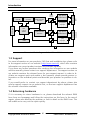
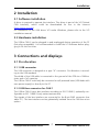
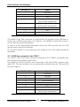
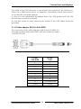
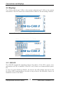
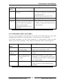
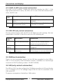
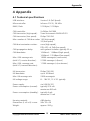
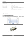
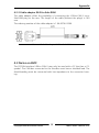
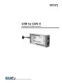
Manual
USB-to-CAN II
Intelligent PC/CAN Interface
The expert for industrial and automotive communication
IXXAT
Headquarter
IXXAT Automation GmbH
Leibnizstr. 15
D-88250 Weingarten
US Sales Office
IXXAT Inc.
120 Bedford Center Road
USA-Bedford, NH 03110
Tel.: +49 (0)7 51 / 5 61 46-0
Fax: +49 (0)7 51 / 5 61 46-29
Internet: www.ixxat.de
e-Mail: [email protected]
Phone: +1-603-471-0800
Fax: +1-603-471-0880
Internet: www.ixxat.com
e-Mail: [email protected]
Support
In case of unsolvable problems with this product or other IXXAT products
please contact IXXAT in written form by:
Fax: +49 (0)7 51 / 5 61 46-29
e-Mail: [email protected]
For customers from the USA/Canada
Fax: +1-603-471-0880
e-Mail: [email protected]
Copyright
Duplication (copying, printing, microfilm or other forms) and the electronic
distribution of this document is only allowed with explicit permission of
IXXAT Automation GmbH. IXXAT Automation GmbH reserves the right to
change technical data without prior announcement. The general business
conditions and the regulations of the license agreement do apply. All rights
are reserved.
Document number: 4.01.0066.20000
Version: 1.5
Contents
1
Introduction .............................................................................. 5
1.1 Overview ............................................................................. 5
1.2 Features .............................................................................. 5
1.3 Support ............................................................................... 6
1.4 Returning hardware ............................................................ 6
2
Installation................................................................................. 7
2.1 Software installation .......................................................... 7
2.2 Hardware installation ......................................................... 7
3
Connections and displays .......................................................... 7
3.1 Pin allocation ...................................................................... 7
3.1.1
3.1.2
3.1.3
3.1.4
USB connector ........................................................................... 7
CAN bus connector for CAN 1 ................................................... 7
CAN bus connector for CAN 2 ................................................... 8
Cable adapter RJ45 to Sub-D9M ................................................ 9
3.2 Displays ............................................................................. 10
3.2.1
3.2.2
3.2.3
3.2.4
USB LED .................................................................................. 10
CAN LEDs (CAN1 and CAN2) ................................................... 11
CAN1 LS LED (only variant automotive) .................................... 12
LIN LED (only variant automotive) ............................................ 12
3.3 CAN bus termination ........................................................ 12
3.4 LIN (only variant automotive) ........................................... 12
4
Appendix ................................................................................. 13
4.1 Technical specifications ..................................................... 13
4.2 Accessories ........................................................................ 14
4.2.1 CAN bus termination resistor ................................................... 14
4.2.2 Cable adapter RJ45 to Sub-D9M .............................................. 15
4.3 Notes on EMC ................................................................... 15
Declaration of conformity ....................................................... 16
FCC Compliance ....................................................................... 17
Copyright IXXAT Automation GmbH
3
USB-to-CAN II - Manual, V1.5
Introduction
1 Introduction
1.1 Overview
Congratulations on your purchase of the IXXAT PC/CAN interface USB-to-CAN II,
a high-quality electronic component developed and manufactured according to
the latest technological standards.
This manual is intended to familiarize you with your interface, also referred to in
the following as USB-to-CAN II. Please read this manual before beginning with
the installation.
1.2 Features
•
•
•
•
•
•
•
•
According to USB specification version 2.0
“Hot-plug“ compatible (plug-in during operation of computer)
Power supply via USB
Infineon 16 bit microcontroller with 36MHz clock
512 kByte RAM
512 kByte Flash
2 CAN controller PHILIPS SJA1000 with 16 MHz clock
variant industrial:
CAN bus interface according to ISO 11898-2, as an option galvanically isolated (both CAN circuits have a common potential)
• variant automotive:
CAN bus interface on CAN 1 can be choosen between high- (ISO 11898-2)
and low-speed (ISO 11898-3), galvanically isolated (both CAN circuits have a
common potential)
CAN bus interface on CAN 2 according to ISO 11898-2, galvanically isolated
LIN bus interface, galvanically isolated (common potential with the CAN bus
interfaces)
Copyright IXXAT Automation GmbH
5
USB-to-CAN II - Manual, V1.5
Introduction
CAN-Controller
SJA1000
USB cable
Low-Speed
TJA1054
MC
C161U
36MHz
CAN-Controller
SJA1000
High-Speed
SN65HVD251
CAN1
High-Speed
SN65HVD251
CAN2/LIN
SRAM
(512 kB)
optional
galvanic
isolation
CAN socket
Flash
(512 kB)
CAN potential
CAN socket
USB potential
LIN
TJA1020
LEDs
only for variant automotive
Picture 1-1: Block diagram of the USB-to-CAN II
1.3 Support
For more information on our products, FAQ lists and installation tips, please refer
to the support section of our website (http://www.ixxat.de), which also contains
information on current product versions and available updates.
If you have any further questions after studying the information on our website
and the manuals, please contact our support department. The support section on
our website contains the relevant forms for your support request. In order to facilitate our support work and enable a fast response, please provide precise information on the individual points and describe your question or problem in detail.
If you would prefer to contact our support department by phone, please also
send a support request via our website first, so that our support department has
the relevant information available.
1.4 Returning hardware
If it is necessary to return hardware to us, please download the relevant RMA
form from our homepage and follow the instructions on this form. In the case of
repairs, please also describe the problem or fault in detail on the RMA form. This
will enable us to carry out the repair quickly.
Copyright IXXAT Automation GmbH
6
USB-to-CAN II - Handbook, V1.5
Installation
2 Installation
2.1 Software installation
A driver is required to operate the interface. This driver is part of the VCI (Virtual
CAN Interface), which could be downloaded for free in the internet
(http://www.ixxat.de).
For installation of the CAN driver VCI under Windows, please refer to the VCI
installation manual.
2.2 Hardware installation
The USB-to-CAN II can be plugged in and unplugged during operation of the PC
(hot-plug compatible). It is recommended to install the VCI software before plugging in for the first time.
3 Connections and displays
3.1 Pin allocation
3.1.1 USB connector
The USB connector is designed as a type “A“ connector. Pin allocation is according to the USB standard.
The shield of the USB cable is connected to the ground of the PCB via a 1MΩ resistor and a 1nF capacitor.
The USB-to-CAN II could only be connected to self-powered hubs (USB-hubs with
own power supply) or directly to the PC
3.1.2 CAN bus connector for CAN 1
The USB-to-CAN II has a bus interface according to ISO 11898-2, optionally configurable as ISO 11898-3 (only variant automotive).
The signals of the bus interface are connected to the 8-pin RJ45 connector (see
table 3-1). The bus interface can be galvanically isolated from the CAN bus as an
option.
Copyright IXXAT Automation GmbH
7
USB-to-CAN II - Manual, V1.5
Connections and displays
Pin No. X5
Signal
1
2
3
4
CAN high
CAN low
GND
CAN high (Fault Tolerant),
(only variant automotive)
CAN low (Fault Tolerant),
(only variant automotive)
Not connected
GND
Not connected
5
6
7
8
Table 3-1: Pin allocation of the CAN bus connector
The shield of the CAN connector is connected to the ground of the CAN bus interface via a 1MΩ resistor and a 1nF capacitor. The shields of both CAN connectors are directly connected together.
In case of a non galvanically decoupled device the CAN ground and the USB
ground have a common potential.
For the best results of noise immunity the shields of the CAN cables should be
grounded.
3.1.3 CAN bus connector for CAN 2
The USB-to-CAN II has a bus interface according to ISO 11898-2, optionally with
LIN interface (only variant automotive).
The signals of the bus interface are connected to the 8-pin RJ45 connector (see
table 3-2). The bus interface can be galvanically isolated from the CAN and LIN
bus as an option.
Pin No. X6
Signal
1
2
3
4
5
6
7
8
CAN high
CAN low
GND
Not connected
Not connected
LIN (only variant automotive)
GND
V-LIN (12V DC, max. 200mA)
(only variant automotive)
Table 3-2: Pin allocation of the CAN bus connector
Copyright IXXAT Automation GmbH
8
USB-to-CAN II - Handbook, V1.5
Connections and displays
The shield of the CAN connector is connected to the ground of the CAN bus interface via a 1MΩ resistor and a 1nF capacitor. The shields of both CAN connectors are directly connected together.
In case of a non galvanically decoupled device the CAN ground and the USB
ground have a common potential.
For the best results of noise immunity the shields of the CAN cables should be
grounded.
3.1.4 Cable adapter RJ45 to Sub-D9M
The connection of the cable adapter could be seen in table 3-3.
The cable could be ordered at IXXAT with the ordering number
1.04.0074.01000.
Picture 3-1: Cable adapter RJ45 to Sub-D9M
Pin No.
Sub-D9M
7
2
3
4
1
5
6
9
Pin No.
RJ45
1
2
3
4
5
6
7
8
8
Not connected
Shield
Shield
Table 3-3: Pin assignment of the cable adapter
Copyright IXXAT Automation GmbH
9
USB-to-CAN II - Manual, V1.5
Connections and displays
3.2 Displays
The USB-to-CAN II has 3 LEDs in the variant industrial and 5 LEDs in the variant
automotive. The LEDs show the communication status of the according interface.
Picture 3-2: Connectors and LEDs of the variant industrial
Picture 3-3 Connectors and LEDs of the variant automotive
3.2.1 USB LED
The USB LED signals the operating state of the device. If the LED is green, communication via USB is possible. If the LED is off, there’s no communication possible.
In case of a green flashing USB LED, the level of the USB voltage may be too low
for safety CAN communication. But this is only a hint of the interface, there’s no
limitation in use of the CANs.
Copyright IXXAT Automation GmbH
10
USB-to-CAN II - Handbook, V1.5
Connections and displays
Flashing Description
mode
off
No communication via USB
possible
Causes/Hints
green
USB communication possible
• Device fully functional
green
blinking
USB communication
• The CAN components need a voltpossible, may be the USB voltage of 5V DC ±5%, but the USB
age is to low for a properly
voltage is under the lower limit at
CAN communication
the moment
CAN communication is still
possible!
• Device not properly initialised, because the USB port can’t provide
enough power
• Device not connected to USB
Table 3-4: States of the USB LED
3.2.2 CAN LEDs (CAN1 and CAN2)
The two coloured (green and red) LEDs for CAN1 and CAN2 flash on each CAN
message (transmitted or received) green, if there was no error detected.
If the CAN controller is in the „Error warning“ or „Error passive“ state, the LED
flashes red on each message. In the „Bus off“ state the LED is continously red.
Flashing
mode
off
Description
Causes/Hints
No CAN
communication
• No CAN communication
• Device not connected to CAN
green / green CAN communication • With each CAN message the LED is trigblinking
gered
red blinking
CAN communication, • The CAN controller is in the „Error
CAN controller in erWarning“ or „Error passive“ state, the
ror state
reception/transmission of CAN messages is still possible
red
Bus Off
• The CAN controller is in the „Bus Off“
state. No more CAN communication
possible
Table 3-5: States of the CAN LEDs
Copyright IXXAT Automation GmbH
11
USB-to-CAN II - Manual, V1.5
Connections and displays
3.2.3 CAN1 LS LED (only variant automotive)
The CAN1 LS LED is yellow. It shows the active bus interface for CAN 1. If the
high speed transceiver is active, the LED is off. In case of the fault tolerant transceiver, the LED is on.
Flashing Description
mode
off
CAN high speed transceiver
active
yellow
Causes/Hints
• The CAN high speed interface is activated
CAN low speed (fault tolerant) transceiver active
• The CAN low speed (fault tolerant)
interface is activated
Table 3-6: States of the CAN1 LS LED
3.2.4 LIN LED (only variant automotive)
The two-coloured (green and red) LED for LIN flashes on each message, that was
transmitted or received. In case of an error the LED is blinking red.
Flashing
mode
off
Description
Causes/Hints
No LIN communication
• There is no LIN communication
• Device not connected to LIN
green / green LIN communication
blinking
• With each LIN message the LED is
triggered
red / red
blinking
• On the transmission or reception of a
LIN message an error was detected
LIN communication
with errors
Table 3-7: States of the LIN LED
3.3 CAN bus termination
There is no bus termination resistor for the CAN bus assembled on the USB-toCAN II. As an accessory a bus termination resistor is available as a feed through
connector at IXXAT (ordering number 1.04.0075.03000).
3.4 LIN (only variant automotive)
The USB-to-CAN II can be configured as LIN Master according to LIN specification
V1.3. A voltage of 12 V DC (voltage range 8-18V DC) has to connected to the
CAN socket X6.
The power consumption is limited by a 1kΩ resistor.
Copyright IXXAT Automation GmbH
12
USB-to-CAN II - Handbook, V1.5
Appendix
4 Appendix
4.1 Technical specifications
USB interface:
Microcontroller:
RAM / Flash:
Version 2.0 (Full Speed)
Infineon C161U, 36 MHz
512 kByte / 512 kByte
CAN controller:
2x Philips SJA1000
CAN transceiver (high speed):
Texas Instruments SN65HVD251
CAN transceiver (low speed):
Philips TJA1054
Max. number of CAN bus nodes: 120 (high speed),
32 (low speed)
CAN bus termination resistor:
none (high speed),
RTH=RTL=4,7kΩ (low speed)
CAN propagation delay:
with galvanic isolation typically 32 ns
CAN baudrates:
10 kBaud – 1 MBaud (high speed),
10 kBaud - 125 kBaud (low speed)
Max. CAN message rate
19900 messages/s (continuous)
(with VCI, receive direction):
21200 messages /s (burst)
Max. CAN- message rate
11300 messages /s (continuous)
(with VCI, transmit direction):
LIN transceiver:
LIN baudrates:
Max. LIN message rate:
LIN voltage range:
Philips TJA1020
up to 20 kBaud
2500 messages/s
8 – 18V DC, 12 V DC typically
Power supply:
Power consumption (normal):
via USB (5V DC)
typically 210 mA
maximum 400 mA
typically 4 mA
maximum 21 mA
Power consumption (standby):
Housing material:
Dimensions (L x B x H) in mm:
Weight:
Copyright IXXAT Automation GmbH
ABS plastics
98 x 55 x 20
approx. 200 g
13
USB-to-CAN II - Manual, V1.5
Appendix
Protection class:
IP40
Operating temperature range:
Storage temperature range:
Relative humidity:
Galvanic isolation:
-20°C - +80°C
-40°C - +85°C
10 - 95%, non-condensing
optional CAN and LIN Bus to USB 250 V AC for
1 min
Device security:
CSA/UL 60950-00 Class 3862 10, 3862 90
4.2 Accessories
4.2.1 CAN bus termination resistor
IXXAT offers a bus termination resistor as a feed through connector (ordering
number 1.04.0075.03000).
Picture 4-1: Connections of the CAN bus termination resistor
Picture 4-2: CAN bus termination resistor
Copyright IXXAT Automation GmbH
14
USB-to-CAN II - Handbook, V1.5
Appendix
4.2.2 Cable adapter RJ45 to Sub-D9M
The cable adapter offers the possibility of connecting the USB-to-CAN II via a
Sub-D9M plug to the user. The length of the cable (without the plugs) is 100
mm.
The ordering number of the cable adapter is 1.04.0074.01000.
Picture 4-3: Cable adapter RJ45 to Sub-D9M
4.3 Notes on EMC
The PC/CAN-Interface USB-to-CAN II may only be used with a PC that has a CEsymbol. The CAN-bus connected to the interface must have a shielded lead. The
shield braiding must be connected with low impedance to the connector housing.
Copyright IXXAT Automation GmbH
15
USB-to-CAN II - Manual, V1.5
Appendix
Declaration of conformity
IXXAT Automation declares that the product:
USB-to-CAN II
with the article number:
1.01.0062.11110
1.01.0062.11220
1.01.0066.11220
do comply with the EC directives 2004/108/EC.
Applied harmonized standards in particular:
EN 55022:2006 + A1:2007
EN 55024:1998 + A1:2001 + A2:2003
22.08.2011, Dipl.-Ing. Christian Schlegel , Managing Director
IXXAT Automation GmbH
Leibnizstrasse 15
88250 Weingarten
Copyright IXXAT Automation GmbH
16
USB-to-CAN II - Handbook, V1.5
Appendix
FCC Compliance
Declaration of conformity
This device complies with Part 15 of the FCC Rules. Operation is subject to the
following two conditions:
• this device may not cause harmful interference, and
• this device must accept any interference received, including interference that
may cause undesired operation.
Class A digital device instructions:
Note: This equipment has been tested and found to comply with the limits for a
Class A digital device, pursuant to Part 15 of the FCC Rules. These limits are designed to provide reasonable protection against harmful interference when the
equipment is operated in a commercial environment. This equipment generates,
uses, and can radiate radio frequency energy and, if not installed and used in accordance with the instruction manual, may cause harmful interference to radio
communications. Operation of this equipment in a residential area is likely to
cause harmful interference in which case the user will be required to correct the
interference at his own expense.
Copyright IXXAT Automation GmbH
17
USB-to-CAN II - Manual, V1.5