1
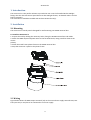
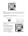
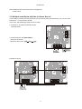
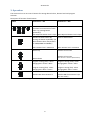
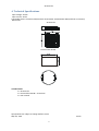
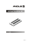
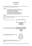
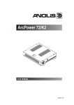
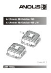
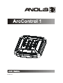
Version 1.1
ArcControl 1
Table of contests
1. Introduction......................................................................................................................................... 3
2. Installation ........................................................................................................................................... 3
2.1 Mounting ....................................................................................................................................... 3
2.2 Wiring ............................................................................................................................................ 3
2.3 Single installation with the ArcPower drivers ............................................................................... 4
2.4 Multiple installation with the ArcPower drivers ........................................................................... 5
3. Operation ............................................................................................................................................ 6
4. Technical Specifications....................................................................................................................... 6
2
ArcControl 1
1. Introduction
The ArcControl 1 is the perfect solution to provide the user control of installed Anolis LED light
fittings.This slim line LED control panel allows to dim LED light fixtures, set desired colours and run
built-in programs.
The ArcControl 1 should be installed with Anolis ArcPower driver(s).
2. Installation
2.1 Mounting
The ArcControl 1 control panel is designed for wall mounting into KU 68 universal box.
To install the ArcControl 1:
1. Prepare the wall by drilling the necessary holes, fitting the KU 68 universal box and cables.
2. Attach the DMX output and power wires to the terminal blocks, being careful to observe the
correct
polarity.
3. Screw the metal frame+plastic frame to the KU 68 universal box.
4. Snap the ArcSource 1 panel to the plastic frame.
2.2 Wiring
Figure below shows the DMX output terminals (P1) on the unit and two supply terminals SV1, SV2 .
The input SV1 (or SV2) has to be connected to a 12 V DC supply.
3
ArcControl 1
Connectors
DMX and supply wires are connected to the self-locking terminals PHOENIX located on the PCB of the
ArcControl 1. Insert each wire directly to the circular hole of the terminal and check its fixation. To
release the wire, insert appropriate tool (narrow flat tip screwdriver) to small rectangle terminal hole
and the wire will be released.
2.3 Single installation with the ArcPower drivers
The ArcPower drivers offer +12 V at DMX input connector (pin 2) which can be used for supply of the
ArcControl 1 unit.
RJ45 socket for DMX IN
(Front view of the socket)
Pin 1: Not connected
Pin 5: +5V
Pin 2: +12V
Pin 6: Data +
Pin 3: Not connected
Pin 4: Not connected
Pin 7: Data Pin 8: GND
Owing to this feature, you can use only one cable for DMX connection and power supply. Use a
suitable cable with 2 twisted-pair of conductors and connect pins 2, 6, 7, 8 of DMX input of the
ArcPower driver.
ArcPower driver setting:
1. Set ArcPower driver to DMX address=1. If you
use two or more drivers, set all DMX addresses at 1.
Note: If you use single colour LED fittings, set
ArcPower SmartWhite driver DMX address at 5.
2. Set RGB or RGBW mode along according to
used LED fittings. See DMX chart of respective
ArcPower driver. Usually it is mode 1 or 2.
(AP driver menu path:
)
3.Set DMX mode in the menu"Protocol".
(AP driver menu path:
)
4
ArcControl 1
Note: GND terminals interconnected on PCB (printed
circuit board).
2.4 Multiple installation with the ArcPower drivers
If you need to control the ArcPower driver (s) from several places simultaneously, you can use more
ArcControl ´s 1 connected in parallel.
In this case, the following changes has to be made .
1. ArcCotrol 1: two pads marked J1 must be
interconnected .
2. ArcPower driver: Set dynet mode in
the menu "Protocol".
(AP driver menu path:
).
Example of wiring
5
ArcControl 1
3. Operation
The ArcControl 1 uses 12 control buttons for setting desired colour, dimmer level and program
selection.
Description of function of each button
Button
ArcControl 1 = ON
ArcControl 1 = OFF
Switches to desired colour.(You
Turns on desired colour
can select from two tones of each
colour by pressing button
repeatedly*)
Note:Adjusted dimmer level is kept Note:Adjusted dimmer level is kept
Switches to white colour. (By
Turns on white colour
pressing the button repeatedly you
select betwen colour temperature
of 3200K,5600K and 8000K*)
Note: Dimmer level = maximum
Note: Dimmer level = maximum
Dimmer up
Switches to last state
Switches to last state
Dimmer down
Note: Dimmer= minimum (both buttons)
Program running (slow)- colour
changing Red-->Green-->Blue
Program running (slow)- colour
changing Red-->Green-->Blue
Program running (fast)- colour
changing Red-->Blue-->Green
Program running (fast)- colour
changing Red-->Blue-->Green
Switches OFF the ArcControl 1
Switches ON the ArcControl 1 (to
the last colour)
* Function is available in Single installation only.
6
ArcControl 1
4. Technical Specifications
Input voltage: 12VDC.
Input current: 15mA
Compatible drivers: ArcPower 36/ArcPower 72/ArcPower 144/ArcPower 360 (and their K2 variants)
Dimensions:
ArcControl 1
Universal box KU 68
Included items
1 x ArcControl 1
1 x Universal box KU 68 + accessories
1 x User manual
Specifications are subject to change without notice.
May 29, 2012
7
Anolis