1
A revolutionary multi PDP
Infinitely expandable multi PDP
Multi-PDP
User’s Manual
Thank you for purchasing our Multi-PDP.
Please read through this user's manual for safety before installing this product.
This product is manufactured for Multi Plasma display model only.
Infinitely expandable
Multi-PDP
Features of Multi-PDP
Enjoy a wide flat screen with high brightness and high quality.
Install and move anywhere thanks to its thin shape.
Enjoy your favorite programs with various split-screen features simultaneously presenting
several programs.
1. Safety Precautions
2. How to install
Thank you for purchasing our Multi-PDP monitor.
This manual describes how to use the product and notes in use.
Please read the manual carefully before using it.
After reading this manual, please retain for future reference along with the original purchase receipt.
If you have any questions or a problem occurs, please contact either the company you purchased this
product from or an authorized service center.
Pausing static picture for around 3 hours may cause an afterimage effect.
Warning If you fail to comply with the regulations for safety and proper use,
fire or injury may be caused.
Notice to users
Class A digital device
Contents
It is a device designed for business purpose with a safety certificate for electromagnetic interference, which
user should be mindful of.
3~4
How to move Multi-PDP
Stand Unit (Option)
Wall Mounting Unit (Option)
5
6
7
8
9
10
3. Guidance for Users
Input/Output Terminals
Set ID Switch Setting
4. How to connect cables
4.1. Connection of one set Multi-PDP
PC & DVI Connection
VCR Connection
DVD & DTV Connection
4.2. Connection of M x N Multi-PDP
4.3. Connection of 3 x 3 Multi-PDP
4.4. Setting ID of M x N Multi-PDP
11
13
15
17~18
19
20
5. Setting and operation of MSCS
Supplied Accessories
User’s Manual
Multi-Screen Control
System(MSCS)
Guide Pin(4pcs)
PC Cable
Power Cable
RS232 Cable
Optional Accessories
CVBS Cable
S-Video Cable
Component Cable
DVI-D Cable
(Length 1.2m & 5m)
(Length 1.2m & 5m)
(Length 1.2m & 5m)
(Length 1.2m & 5m)
Wall mounting Unit
Stand Unit
RS-232C Distributor
(refer to page 7)
(refer to page 6)
(Recommended for4 x 4 or more units.)
5.1. Setting 'Com Port'
5.2 “Last design/New design” setting
5.3 Setting 'Multi-Screen' Configuration
5.4 Remote Control
5.5 ID Setting
5.6 Configuration of various modes
5.7 Setting multi screens at a time
5.8 Slide Control
5.9 MSCS Size Control
5.10 Picture Control
5.11 Auto Tracking
5.12 Setting “Time On/Off”
5.13 Test Pattern
5.14 WVGA Mode
5.15 WXGA Mode
5.16 Orion PDP Home Page logon and Version information
6. MSCS Protocol
7. Other tips
7.1 Before calling for service
7.2 About Plasma display panel
22
22
23
24
24
25
26
27
29
30
31
32
33
33
34
34
35~39
40
41
8. Resolution of PC video signal
8.1 DVD/DTV
8.2 PC & DVI
1 Input, 6 Output
1
42
42
43
9. Specifications
2
Infinitely expandable
Multi-PDP
1. Safety Precautions
If it operates abnormally, stop using it
immediately.
Do not place any liquid-containing
container on it. If the inside is wet, it
may cause electric shock or fire.
Do not put any foreign material into the
product. It may cause a failure or
shorten the life span.
Do not pull out or hang down the
connection cable. It may damage the
cord to cause fire or electric shock.
Do not lean against the product or keep
it leaned. It may cause injury or failure.
Do not put it at any place with much
humidity, dust, oil, smoke or steam. It
may cause failure.
Please refer to a specialized
construction company for installing
stand or wall mount unit. Otherwise,
damage or injury may be caused.
Do not touch the device when lightning
strikes.
Do not install in an unstable location
It may cause injury.
Pull out the power plug by holding the
plug. Otherwise, it may damage the
power cord to cause fire or electric
shock.
If you do not want to use the product for
a long time, keep the power plug
unplugged to save electricity.
The socket-outlet should be installed
near the equipment and be easily
accessible.
Do not put any heavy object on it.
It may cause failure.
Avoid any action to damage the power
code or power plug. It may cause fire
or electric shock.
Do not pull out the power plug with a
wet hand. It may cause electric shock.
Do not exceed ratings of AC outlet
or extension cords. It may cause
failure.
Install the product on safe and flat
surface.
Do not ride or step on the product It may
cause breakage when fallen down.
When moving it, disconnect the
connecting cable. Otherwise, it may
damage the cable to cause fire or
electric shock.
Do not alter (or disassemble) the
product. It may cause electric shock
since high voltage is flowing inside.
Do not install the product where it may
be exposed to direct sunlight or near
any heating device. It may shorten the
product's life span or cause failure.
Do not put candles on the product. If the
liquid flows inside the product. It may
cause electric shock or fire.
Do not touch product’s front surface
with hand. Otherwise, the image quality
can be lowered.
3
Make sure the product is not covered with
any object. If the venting hole is blocked,
the inside temperature may rise to cause
overheating resulting in fire.
4
Infinitely expandable
Multi-PDP
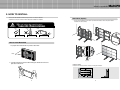
2. HOW TO INSTALL
• The set can be installed in diverse ways such as on a wall, or stand etc.
• Install this set only at a location where adequate ventilation is available.
Stand Unit (Option)
• The set can be installed as shown below. (For further information, refer to the optional 'Stand
Installation and Setup Guide'.)
Do not incline the panel forward.
Attention
PANEL
PANEL
PANEL
Guide Pin
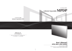
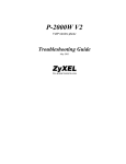
How to move Multi-PDP
1. 2 people hold each handle on product’s back side
Stand
Stand
PDP
Handles
Hanger Bolt
2. 2 people transfer the product with holding the handle and the front
part at the same time.
5
Install on a Stand
Pedestal mount allowing minimum clearance for adequate ventilation.
6
Infinitely expandable
3. Guidance for Users
Front view
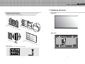
Wall Mounting Unit (Option)
• The set can be installed on the wall as shown below.
(For further information, refer to the optional ‘Wall Mounting Bracket Installation and Setup Guide'.)
Guide Pin
Back view
Hanger
Hanger
PDP
RS-232C OUT
RS-232C IN
VIDEO
IN
OUT
S-VIDEO
IN
OUT
COMPONENT
OUT
IN
PC
IN
Hanger Bolt
DVI-D OUT
OUT
DVI-D IN
AC INPUT
Mount on the wall
Wall mount allowing minimum clearance for adequate ventilation.
7
8
Multi-PDP
Infinitely expandable
Input/Output Terminals
Multi-PDP
Set ID Switch Setting
• Example of switch
- This is Dyadic System. In case of PDP set ID 1 and ID 9, set the ID switch as shown in the
below figure
RS-232C OUT
RS-232C IN
VIDEO
IN
OUT
S-VIDEO
IN
OUT
COMPONENT
RS-232C OUT
RS-232C IN
VIDEO
IN
OUT
S-VIDEO
OUT
IN
IN
OUT
COMPONENT
PC
IN
DVI-D OUT
OUT
OUT
IN
DVI-D IN
PC
IN
DVI-D OUT
OUT
DVI-D IN
AC INPUT
AC INPUT
1. RS-232C
Multi-PDP Control, Firmware Upgrade, 9pin D-sub
2.Video
Composite Signal
NTSC, PAL, SECAM
ON
ON
3.S-Video
S-Video Signal
NTSC, PAL, SECAM, 4pin Mini Din
Pr
Pb
1 2 3 4 5 6 7 8
1 2 3 4 5 6 7 8
[PDP ID 1]
[PDP ID 9]
4.Component
DVD Signal
DTV - YPbPr Signal
Y
5. PC
Computer RGB Analog Signal, D-sub 15pin
6. DVI-D
TMDS Signal
7. ID Switch
Set ID Switch
8. AC Input
AC 100V ~240V, 50/60Hz
9
10
Infinitely expandable
Multi-PDP
4. How to Connect Cables
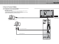
4.1. Connection of one set multi-PDP
PC & DVI Connection
RS-232C OUT
• MSCS (Multi-Screen Control System) that we supply and RS-232C of PDP monitor can
control all functions of Multi-PDP, such as On/Off and screen control.
• To control Multi-PDP through PC, the Identity number of each Multi-PDP must be unique.
• RS-232C of each Multi-PDP and PC should be connected.
RS-232C IN
VIDEO
IN
OUT
S-VIDEO
IN
OUT
COMPONENT
OUT
IN
PC
IN
DVI-D OUT
OUT
DVI-D IN
AC INPUT
1 2 3 4 5 6 7 8
[PDP ID 1]
RS-232C
PC (MSCS) to control Multi-PDP
• ID switch must be set as
ID 1 for one set use.
RS-232C OUT
RS-232C IN
VIDEO
1 2 3 4 5 6 7 8
IN
OUT
S-VIDEO
IN
OUT
COMPONENT
Pr
PC
Pb
Y
When connecting to PC-ANALOG
OUT
IN
PC
When connecting to DVI
IN
DVI-D OUT
11
OUT
DVI-D IN
12
Infinitely expandable
Multi-PDP
VCR Connection
RS-232C OUT
RS-232C IN
VIDEO
IN
OUT
S-VIDEO
IN
OUT
COMPONENT
OUT
IN
PC
IN
DVI-D OUT
OUT
DVI-D IN
AC INPUT
1 2 3 4 5 6 7 8
[PDP ID 1]
RS-232C
PC(MSCS) to control Multi-PDP
RS-232C OUT
RS-232C IN
VIDEO
1 2 3 4 5 6 7 8
IN
When connecting to Video
OUT
S-VIDEO
IN
When connecting to S-Video
OUT
COMPONENT
Pr
Pb
Y
OUT
IN
PC
VCR
IN
DVI-D OUT
13
OUT
DVI-D IN
14
Infinitely expandable
Multi-PDP
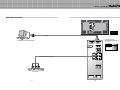
DVD & DTV Connection
RS-232C OUT
RS-232C IN
VIDEO
IN
OUT
S-VIDEO
IN
OUT
COMPONENT
OUT
IN
PC
IN
DVI-D OUT
OUT
DVI-D IN
AC INPUT
1 2 3 4 5 6 7 8
[PDP ID 1]
RS-232C
• Component Input ports
PC(MSCS) to control Multi-PDP
RS-232C OUT
RS-232C IN
You can get better image quality by
connecting DVD player to component input
ports as below.
Component ports of
the set
Y
Video output ports
of DVD player
Y Pb Pr
Y B-Y R-Y
Y Cb Cr
Pb
Pr
VIDEO
1 2 3 4 5 6 7 8
IN
OUT
S-VIDEO
IN
OUT
COMPONENT
Pr
Pb
When connecting to Component
Y
OUT
IN
PC
IN
OUT
DVD & DTV
DVI-D OUT
15
DVI-D IN
16
Multi-PDP
Infinitely expandable
4.2. Connection of M x N Multi-PDP
RS-232C OUT
RS-232C IN
RS-232C OUT
RS-232C IN
VIDEO
IN
• When connecting a number of Multi-PDP through Daisy Chain(Link), surrounding noise may
come out to lower the image quality.
IN
IN
IN
IN
PC
IN
DVI-D OUT
PC
OUT
IN
DVI-D IN
DVI-D OUT
RS-232C IN
IN
IN
IN
OUT
IN
IN
DVI-D OUT
PC
OUT
IN
DVI-D IN
DVI-D OUT
RS-232C IN
RS-232C OUT
RS-232C IN
VIDEO
OUT
IN
VIDEO
OUT
IN
S-VIDEO
OUT
IN
OUT
IN
IN
DVI-D OUT
OUT
IN
PC
OUT
DVI-D IN
OUT
COMPONENT
OUT
IN
OUT
S-VIDEO
OUT
COMPONENT
PC
IN
DVI-D OUT
AC INPUT
RS-232C OUT
VIDEO
S-VIDEO
COMPONENT
IN
OUT
DVI-D IN
AC INPUT
AC INPUT
RS-232C IN
IN
OUT
IN
PC
OUT
DVI-D IN
IN
OUT
COMPONENT
OUT
IN
OUT
S-VIDEO
OUT
COMPONENT
PC
RS-232C OUT
RS-232C IN
VIDEO
OUT
S-VIDEO
OUT
IN
DVI-D OUT
RS-232C OUT
VIDEO
OUT
COMPONENT
IN
AC INPUT
RS-232C OUT
VIDEO
S-VIDEO
IN
OUT
DVI-D IN
AC INPUT
AC INPUT
RS-232C IN
IN
OUT
IN
PC
OUT
DVI-D IN
• In case of lower image quality, it is advisable to use a distributor that can provide resolution over
UXGA (1600*1200 @ 60Hz).
RS-232C OUT
OUT
COMPONENT
OUT
IN
OUT
S-VIDEO
OUT
COMPONENT
OUT
IN
DVI-D OUT
RS-232C IN
VIDEO
OUT
S-VIDEO
OUT
IN
RS-232C OUT
VIDEO
OUT
S-VIDEO
IN
COMPONENT
PC
OUT
IN
DVI-D IN
DVI-D OUT
OUT
DVI-D IN
AC INPUT
AC INPUT
AC INPUT
RS-232C
PC (MSCS) to control Multi-PDP
RS-232C OUT
RS-232C IN
RS-232C OUT
RS-232C IN
VIDEO
1 2 3 4 5 6 7 8
OUT
OUT
IN
RS-232C IN
OUT
IN
RS-232C IN
OUT
IN
RS-232C IN
OUT
IN
RS-232C IN
IN
RS-232C IN
VIDEO
1 2 3 4 5 6 7 8
OUT
IN
S-VIDEO
OUT
RS-232C OUT
VIDEO
1 2 3 4 5 6 7 8
IN
S-VIDEO
OUT
RS-232C OUT
VIDEO
1 2 3 4 5 6 7 8
IN
S-VIDEO
OUT
RS-232C OUT
VIDEO
1 2 3 4 5 6 7 8
IN
S-VIDEO
OUT
RS-232C OUT
VIDEO
1 2 3 4 5 6 7 8
IN
S-VIDEO
OUT
RS-232C OUT
VIDEO
1 2 3 4 5 6 7 8
IN
S-VIDEO
IN
RS-232C IN
VIDEO
1 2 3 4 5 6 7 8
IN
RS-232C OUT
OUT
IN
S-VIDEO
OUT
IN
OUT
S-VIDEO
OUT
IN
OUT
COMPONENT
COMPONENT
COMPONENT
COMPONENT
COMPONENT
COMPONENT
COMPONENT
COMPONENT
Pr
Pr
Pr
Pr
Pr
Pr
Pr
Pr
Pb
Pb
Pb
Pb
Pb
Pb
Pb
Pb
S-VIDEO
Y
Y
OUT
IN
PC
IN
Y
OUT
IN
PC
OUT
IN
Y
OUT
IN
PC
OUT
IN
Y
OUT
IN
PC
OUT
IN
Y
OUT
IN
PC
OUT
IN
Y
OUT
IN
PC
OUT
IN
Y
OUT
IN
PC
OUT
IN
OUT
IN
PC
OUT
IN
OUT
PC
DVI-D OUT
PDP1
17
DVI-D IN
DVI-D OUT
PDP2
DVI-D IN
DVI-D OUT
PDP3
DVI-D IN
DVI-D OUT
DVI-D IN
PDP4
DVI-D OUT
DVI-D IN
PDP5
DVI-D OUT
DVI-D IN
PDP6
18
DVI-D OUT
DVI-D IN
PDP7
DVI-D OUT
PDP8
DVI-D IN
Infinitely expandable
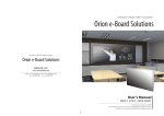
4.3. Connection of 3 x 3 Multi-PDP
ID 1
4.4. Setting ID of M x N Multi-PDP
ID 2
RS-232C OUT
PC
RS-232C IN
IN
PC
RS-232C IN
OUT
ID 4
IN
RS-232C OUT
PC
RS-232C IN
IN
PC
RS-232C IN
OUT
IN
RS-232C OUT
PC
RS-232C IN
IN
OUT
PC
RS-232C IN
OUT
ID 8
RS-232C OUT
IN
ID 6
RS-232C OUT
ID 7
PC
RS-232C IN
OUT
ID 5
RS-232C OUT
• Identity number (ID) indicates the location of each Multi-PDP.
• When you look at the Multi-PDP screens in front of Multi-PDP.
ID 3
RS-232C OUT
IN
PC
RS-232C IN
OUT
IN
RS-232C OUT
PC
RS-232C IN
OUT
IN
PDP ID
1
PDP ID
2
PDP ID
3
PDP ID
4
PDP ID
5
PDP ID
6
PDP ID
7
PDP ID
8
PDP ID
9
PDP ID
10
PDP ID
11
PDP ID
12
PDP ID
13
PDP ID
14
PDP ID
15
PDP ID
16
PDP ID
17
PDP ID
18
PDP ID
19
PDP ID
20
PDP ID
21
PDP ID
22
PDP ID
23
PDP ID
24
PDP ID
25
OUT
ID 9
RS-232C OUT
Multi-PDP
OUT
Recommended ID of M x N screens
PC Signal Distributor
(UXGA : over 250MHz)
ID 1
1 2 3 4 5 6 7 8
ID 6
1 2 3 4 5 6 7 8
ID 11
1 2 3 4 5 6 7 8
ID 16
1 2 3 4 5 6 7 8
ID 21
PC
RS-232C control PC
19
1 2 3 4 5 6 7 8
ID 2
1 2 3 4 5 6 7 8
ID 7
1 2 3 4 5 6 7 8
ID 12
1 2 3 4 5 6 7 8
ID 17
1 2 3 4 5 6 7 8
ID 22
1 2 3 4 5 6 7 8
ID 3
1 2 3 4 5 6 7 8
ID 8
1 2 3 4 5 6 7 8
ID 13
1 2 3 4 5 6 7 8
ID 18
1 2 3 4 5 6 7 8
ID 23
1 2 3 4 5 6 7 8
20
ID 4
1 2 3 4 5 6 7 8
ID 9
1 2 3 4 5 6 7 8
ID 14
1 2 3 4 5 6 7 8
ID 19
1 2 3 4 5 6 7 8
ID 24
1 2 3 4 5 6 7 8
ID 5
1 2 3 4 5 6 7 8
ID 10
1 2 3 4 5 6 7 8
ID 15
1 2 3 4 5 6 7 8
ID 20
1 2 3 4 5 6 7 8
ID 25
1 2 3 4 5 6 7 8
Infinitely expandable
Multi-PDP
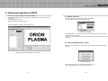
5. Setting and operation of MSCS
• MSCS is an application program needed to control MPDP.
• Activate MSCS setup file. Directory is created in C:/ MSCS(v.2.0) and shortcut is made on
the monitor.
• Activate MSCS(v2.0) exe file
Main image of MSCS is as shown below.
5.1. Setting 'Com Port'
• Com Port connects and disconnects between PC and MPDP.
• Connect MPDP to PC Com Port via RS-232C cable.
• System Requirements : Window® 2000 or Window® XP
Communication Setting
• Go to MSCS Menu –> Communication and set Com Port. Click 'Connect' using mouse or
press 'Ctrl+C' using keyboard.
• In order to disconnect communication, click 'Disconnect' using mouse or press 'Ctrl+D' using
keyboard.
5.2 “Last design/New design” setting
• When Com Port is successfully connected, pop-up window for “Last design/New design”
appears.
Main Image of MSCS (Multi Screen Control system)
Last/New Design Set
• Click “Open Last Design” to go to latest design before closing.
• Click “Open New Design” to prepare new configuration.
21
22
Infinitely expandable
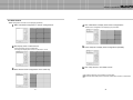
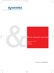
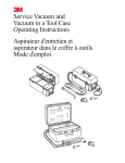
5.3 Setting 'Multi-Screen' Configuration
Multi-PDP
5.4 Remote Control
-Check “ALL PDP” to send data to all connected MPDP regardless of ID.
Screen Configuration Setting
a desirable X number and Y number
1 Select
-X number represents the number of MPDP columns and Y number represents the
PDP Control - Power On/Off
-In order to control power of specific MPDP, use “Power On/Off” button after selecting the
specific MPDP.
number of MPDP rows.
-The range of X.Y number is from 1 to 5
one out of 6 input sources such as DVI, PC, DTV, DVD, S-VIDEO
2 Select
and VIDEO.
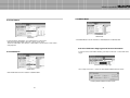
5.5 ID Setting
• ID of MSCS is set automatically.
“play” button
3 Press
-Desired configuration is set up in “Screen Configuration” after selecting input source
in “Select Input” and setting X number and Y number are completed.
ID 1
ID 2
ID 3
ID 4
ID 5
ID 6
ID 7
ID 8
ID 9
Example of PDP ID Setting
(Input signal is DVI, Configuration is 3 by 3)
• In order to transmit data to chosen MPDP, ID of Screen Configuration must be selected.
• Select ID using right button of mouse. Selected ID is displayed with red square box.
23
24
Infinitely expandable
5.6 Configuration of various modes
5.7 Setting multi screens at a time
• You can configure various input sources as you want.
• You can select multi screens at a time as you want.
Multi-PDP
a desirable input Source in “Select Input”
1 Select
Ex) Select “DVI” in “Select Input”
a desirable input source in “Select Input”
1 Select
-Select “DVI” in “Select Input”.
desirable screen with left button of mouse then the screen would
2 Click
be converted into DVI.
2 Select screens with left button of mouse and drag from the first screen.
can configure other screens in the same way.
3 You
-Selected screen would be converted into DVD.
3 Selected screens would be converted into DVI.
• Click 'Play' button on the main image of MSCS or scroll using mouse to return to initial image.
25
26
Infinitely expandable
Multi-PDP
5.8 Slide Control
• MPDP configuration that users set is displaying repeatedly.
1 Make a desirable configuration in “Screen Configurations”
“Slide Start” to display saved screen configurations.
4 Click
-Saved screen configurations are displaying for preset time.
“Display Time” in “Slide Control”
2 Set
-Click “Add” button to save configuration.
5 Check “Repeat” to display saved configuration repeatedly.
-The range of “Display Time” is from 10 seconds to 1 hour.
3
Save diverse screen configurations in the same way.
6 Click “Stop” button to end “Slide Control”
To view the slide form, click ‘List Box’ of saved slide.
To transmit saved slide protocol command, double click ‘List Box’ of saved slide.
27
28
Infinitely expandable
5.9 MSCS Size Control
Multi-PDP
5.10 Picture Control
• The dialog size of MSCS can be set in three levels of small, medium and large as indicated
below.
• Register values related to display of MPDP can be changed.
• Click “Picture Control” of “Control” menu bar or enter “Ctrl+W” in order to run “Picture
Control” window.
Picture Control
• In order to control display values, input values directly in “Edit Box” and press Enter key.
Or click -/+ button using mouse.
• Check “All PDP” to transmit command data to all connected MPDPs regardless of ID.
• Click “Reset” button to initialize the values.
• Click “Exit” button or press “Ctrl+X” using keyboard to close “Picture Control” window.
29
30
Infinitely expandable
5.11 Auto Tracking
Multi-PDP
5.12 Setting “Time On/Off”
• Alignment adjustment is available when input source is PC.
• MPDP turns on and off through designated time schedule set by users.
• In order to activate timer window, go to Control menu bar –> Timer or enter “Ctrl+T” using
keyboard.
• Go to “Control” in menu bar –> “Tracking” –> “Auto” in order to run “Tracking Auto” window.
• In case alignment doesn't work through “Tracking Auto”
command, users can tune finely through “Tracking Manual”. Go
to “Control” of menu bar –> “Tracking” –> “Manual” or press
“Ctrl+M” using keyboard.
• “Tracking Manual” window enables users to set Frequency,
Phase, LineStart and PixelStart.
• When “Tracking Manual” window is on display, users cannot
display “Picture Control” window.
• Even when “Tracking Manual” window is on display, setting “ID”
is available by clicking right button of mouse.
(Refer to “5.5 PDP ID Setting”.)
Tracking Manual Window
• Detail adjustment steps are as follows.
1) Tune “Phase” until the vertical lines are clearly adjusted..
2) Tune “LineStart” to adjust vertical alignment. “PixelStart” for horizontal alignment.
3) Adjust “Frequency” if alignment is still wrong.
If you adjust “Frequency”, repeat step 1) and 2) to fit alignment.
- The range of Frequency, LineStart, PixelStart you can adjust is from -50 to 50
- The range of Phase you can adjust is from 0 to 31.
• Check “All PDP” button to transmit tracking command data to all connected MPDPs
regardless of ID.
• Click “ Exit” button or press “Ctrl+X” using keyboard to close “Tracking Manual” window.
31
Timer
• Follow as described below to control “On Time” or “Off Time”.
Set hour and minute in “On Time”.
Check “Once” for only one time running and check “Daily” for daily running of “On Time”
function.
• Follow “On Time” to control “Off Time” function.
• “Timer On/Off” function lasts even though the “Timer” window is closed.
• Users can not set same time in “On Time” and “Off Time”.
32
Infinitely expandable
Multi-PDP
5.15 WXGA Mode
5.13 Test Pattern
Test Pattern
- In order to display “Test Pattern”, go to “Test Pattern” in Control menu.
Click Red, Green, Blue, White or use Ctrl+1, Ctrl+2, Ctrl+3, Ctrl+4.
To exit from Test Pattern, click “Screen” in Test Pattern of Control menu or enter “Ctrl+5”
using keyboard.
WXGA Mode
- Click WXGA Mode for the PC resolution of 1280x768,60Hz or 1366x768, 60Hz
5.16 Orion PDP Home Page logon and Version information
5.14 WVGA Mode
• In order to move to Orion PDP's website, go to “Help” of menu bar –> ”Orion PDP Home
Page”.
Orion PDP Home Page Logon
WVGA Mode
• Go to “Help” of menu bar –> ”About” to check MSCS & MPDP Firmware version.
- Click WVGA Mode for the PC resolution of 853x480 60Hz.
Checking MSCS & MPDP Firmware Version
33
34
Infinitely expandable
Multi-PDP
6. MSCS Protocol
1. Protocol Form
2. Protocol Value
1.1. Type 1 – Individual Command
2.1. Command
1) Send To PDP
Command
PDP ID
Sub
Command
End
4byte
2byte
4byte
1byte
Send To PDP
(Send Data)
ASCII
6;
Hex
0x36
4=
0x3B
0x34
Test Pattern MDIN
In Off
0x3D
Test Pattern MDIN
Out On
EX) 6;4=01526>
2) Receive From PDP
6;4= : Send Command[COMMAND]
01 : Set 1 [ PDP ID]
526> : Power On[SUB COMMAND]
Receive From PDP ASCII
(Response Data)
Hex
6;
0x36
Test Pattern MDIN
Out Off
4>
0x3B
0x34
ASCII
Hex
ASCII
Hex
ASCII
Hex
52
0x35
37
0x32
0x33
52
0x35
0x32
0x33
52
0x35
0x37
38
0x38
39
0x32
0x33
0x32
0x33
0x39
0x3E
5) Mode Command
2.2. PDP ID
1.2. Type 2 – Multi Scale Command
Command
PDP ID
Sub
Command
M
(Width)
N
(Height)
P
(Position)
S
(Source)
End
4byte
2byte
4byte
4byte
4byte
4byte
4byte
1byte
PDP ID : 1
01
PDP ID : 6
06
PDP ID : 11
0;
PDP ID : 16
10
PDP ID : 21
15
EX) 6;4=014=7303030170
6;4= : Send Command [Command]
01 : Set 1 [PDP ID]
4=73 : Multi Scale Command [Sub Command]
0303 : Set Configulation ( 3 x 3 ) [M (Width), N(Height)]
01 : Picture Position (first picture) [P(Position)]
70 : DVI Input [S (Source)]
Command
PDP ID
4byte
2byte
4byte
End
Adjustment
Value
1byte
PDP ID : 4
04
PDP ID : 9
09
PDP ID : 14
0>
PDP ID : 19
13
PDP ID : 24
18
VGA Mode
PDP ID : 5
05
PDP ID : 10
0:
PDP ID : 15
0?
PDP ID : 20
14
PDP ID : 25
19
WVGA Mode
XGA Mode
WXGA Mode
Power Off
ASCII
Hex
ASCII
Hex
Always Power On
Enable
Always Power On
Disable
52
0x35
0x32
0x36
0x32
0x36
6;4= : Send Command
01 : Set 1
4761 : Adjust Graphic Mode Brightness
0> : Change brightness value 14
52
0x35
Tracking Auto
Hex
0x32
0x36
52
61
0x32
0x36
PC
0x31
DTV
1.4. Type 4 – Get Data Command
4) Test Pattern Command
Send To PDP
Command
4byte
PDP ID
2byte
Receive From PDP
Sub
Command
4byte
End
Command
1byte
4byte
EX) 6;4=015241
PDP ID
Sub
Command
2byte
4byte
EX) 6;4>015241000:0511
6;4= : Send Command
01 : Set 1
5241 : Get tracking-manual data
6;4> : Receive Command
01 : Set 1
5241 : Get tracking-manual data
00 : Frequency value 0
0: : Phase value 10
05 : Line start value 5
11 : Pixel start value 17
35
ASCII
Hex
ASCII
Test Pattern Green
Hex
ASCII
Test Pattern Blue
Hex
ASCII
Test Pattern White
Hex
ASCII
Test Pattern
Screen
Hex
Test Pattern VPC ASCII
On
Hex
Test Pattern VPC ASCII
Off
Hex
Test Pattern MDIN ASCII
In On
Hex
Test Pattern Red
Data
Variable
End
1byte
DVD
52
0x35
72
0x32
0x37
52
0x35
0x36
52
0x32
0x36
0x32
0x37
0x32
0x37
0x32
43
0x32
0x34
0x33
63
0x32
0x36
52
0x35
0x32
0x34
52
0x35
VIDEO
42
52
0x35
0x37
77
52
0x35
S-VIDEO
62
52
0x35
0x32
67
0x32
0x35
0x32
0x33
52
0x35
0x32
0x33
52
0x35
0x32
33
0x33
34
0x32
0x33
0x32
0x36
0x34
ASCII
Hex
ASCII
Hex
52
0x35
6?
52
0x35
0x3F
75
0x32
0x37
0x3D
0x37
0x35
ASCII
Hex
4=
0x34
73
0x33
2) Send Data : Multi Scal Data -> Source
0x3C
DVI
0x35
0x35
0x31
32
6<
3) Auto Tracking Command
ASCII
52
2.3.2. Multi Scale Command
1) Sub Command
0x36
Multi Scale
Picture Control Reset ASCII
Graphic(DVI, PC, DTV) Hex
31
0x3E
66
2) Reset Command
EX) 6;4=0147610>
52
0x35
6>
52
0x35
ASCII
Hex
ASCII
Hex
ASCII
Hex
ASCII
Hex
6) Factory Mode Command
2.3.1. Individual Set Command
1) Power Command
Power On
Data
PDP ID : 3
03
PDP ID : 8
08
PDP ID : 13
0=
PDP ID : 18
12
PDP ID : 23
17
2.3. Sub Command
1.3. Type 3 – Adjustment Command
Sub
Command
PDP ID : 2
02
PDP ID : 7
07
PDP ID : 12
0<
PDP ID : 17
11
PDP ID : 22
16
0x33
36
0x32
0x33
0x36
36
ASCII
Hex
ASCII
Hex
ASCII
Hex
ASCII
Hex
ASCII
Hex
ASCII
Hex
69
0x36
0x39
70
0x37
0x30
74
0x37
0x34
64
0x36
0x34
73
0x37
0x33
76
0x37
0x36
Infinitely expandable
2.3.3. Adjustment Command
1) Picture Control Graphic User Mode Command
ASCII
User Mode
Graphic - Brightness Hex
ASCII
User Mode
Graphic - Contrast
Hex
ASCII
User Mode
Graphic - Sharpness Hex
ASCII
User Mode
Graphic - Saturation
Hex
ASCII
User Mode
Graphic - Hue
Hex
47
0x34
0x36
47
0x34
0x36
47
0x36
47
0x34
White Balance
Video - Gamma R
0x35
White Balance
Video - Gamma G
64
0x37
0x36
47
0x34
0x33
White Balance
Video - Gain B
63
0x37
0x34
0x32
White Balance
Video - Gain G
62
0x37
0x34
0x31
White Balance
Video - Gain R
61
0x37
65
0x37
0x36
White Balance
Video - Gamma B
2) Picture Control Graphic White Balance Command
White Balance
Graphic - Gain R
White Balance
Graphic - Gain G
White Balance
Graphic - Gain B
White Balance
Graphic - Gamma R
White Balance
Graphic - Gamma G
White Balance
Graphic - Gamma B
White Balance
Graphic - Csc R
White Balance
Graphic - Csc G
White Balance
Graphic - Csc B
White Balance
Graphic - Bias
ASCII
Hex
ASCII
Hex
ASCII
Hex
ASCII
Hex
ASCII
Hex
ASCII
Hex
ASCII
Hex
ASCII
Hex
ASCII
Hex
ASCII
Hex
47
0x34
0x36
47
0x34
0x37
0x36
0x37
0x37
0x36
0x37
0x36
ASCII
Hex
ASCII
Video Data
Component Cb
Hex
ASCII
Video Data
Component Tint
Hex
ASCII
Video Data
Component Brightness Hex
ASCII
Video Data
Component Contrast Hex
ASCII
Video DataLuma
Brightness
Hex
ASCII
Video DataLuma
Contrast
Hex
ASCII
Video DataLuma
Saturation
Hex
Video Data
Component Cr
0x3B
0x36
0x3C
6=
0x37
0x36
47
0x3D
6>
0x37
0x36
47
0x3E
6?
0x37
0x36
0x3F
3) Picture Control Graphic RGB-YUV Data Command
Graphic Data
Gain R
Graphic Data
Gain G
Graphic Data
Gain B
Graphic Data
Offset R
Graphic Data
Offset G
Graphic Data
Offset B
ASCII
Hex
ASCII
Hex
ASCII
Hex
ASCII
Hex
ASCII
Hex
ASCII
Hex
47
0x34
70
0x37
47
0x34
0x37
47
0x34
0x37
47
0x34
0x37
47
0x34
0x37
47
0x34
0x37
0x37
0x30
q(0x71)
0x37
0x31
72
0x37
0x32
73
0x37
0x33
74
0x37
0x34
75
0x37
0x35
User Mode Video Contrast
User Mode Video Sharpness
User Mode Video Saturation
User Mode Video Hue
ASCII
Hex
ASCII
Hex
ASCII
Hex
ASCII
Hex
ASCII
Hex
56
0x35
Tracking Manual
Frequency
Tracking Manual
Phase
Tracking Manual
Line Start
Tracking Manual
Pixel Start
61
0x36
0x36
56
0x35
0x36
0x35
0x36
0x36
0x36
0x36
0x36
0x35
0x32
Graphic Data,
Video Data
0x33
64
56
0x34
65
0x36
0x36
0x35
66
0x36
0x36
56
0x35
0x36
0x36
56
0x35
0x36
0x36
0x36
0x36
0x36
0x36
0x36
0x36
0x36
0x36
0x36
0x36
0x36
0x36
0x3D
0x35
0x3E
6?
0x3F
Get Data
Tracking Manual
0x36
0x35
0x37
0x36
0x35
0x37
0x36
0x37
0x36
0x37
0x34
75
0x36
0x37
56
0x35
76
0x36
0x37
56
0x35
0x33
74
56
0x35
0x32
73
0x36
0x35
0x31
0x37
56
0x35
Receive Data :
10byte
72
56
0x35
0x30
71
56
0x37
ASCII
Hex
ASCII
Hex
ASCII
Hex
ASCII
Hex
0x32
0x34
52
0x35
0x36
Get Data
White Balance Data
0x35
0x37
0x32
0x35
0x35
0x30
4<
0x32
0x34
52
0x35
0x36
50
52
0x3C
58
0x32
0x35
ASCII
Hex
0x38
0x36
High Value
Get Data
Total Data
0x31
Data[0]
Data[1]
Data[2]
Data[3]
Data[4]
Data[5]
Data[6]
Data[7]
Low Value
ASCII
Hex
52
0x35
Data[0]
Data[1]
Data[2]
Data[3]
Data[4]
Data[5]
Data[6]
Data[7]
Data[8]
Data[9]
Receive Data : 58byte
(User Data:10byte)
41
0x32
0x34
0x31
Brightness High Value
Brightness Low Value
Contrast High Value
Contrast Low Value
Sharpness High Value
Sharpness Low Value
Saturation High Value
Saturation Low Value
Hue High Value
Hue Low Value
ASCII
Hex
47
0x34
Receive Data :
20byte
Data[0]
Data[1]
Data[2]
Data[3]
Data[4]
Data[5]
Data[6]
Data[7]
Data[8]
Data[9]
Data[10]
Data[11]
Data[12]
Data[13]
Data[14]
Data[15]
Data[16]
Data[17]
Data[18]
Data[19]
Receive Data : 58byte
(White Balance
Data:30byte)
57
0x37
0x35
0x37
Receive Data : 58byte
(RGB-YUV Data :
12byte)
Gain R High Value
Gain R Low Value
Gain G High Value
Gain G Low Value
Gain B High Value
Gain B Low Value
Gamma R High Value
Gamma R Low Value
Gamma G High Value
Gamma G Low Value
Gamma B High Value
Gamma B Low Value
Csc R High Value
Csc R Low Value
Csc G High Value
Csc G Low Value
Csc B High Value
Csc B Low Value
Bias High Value
Bias Low Value
Receive Data : 58byte
(Component Data :
10byte)
&(Composite Data :
6byte)
0x35
37
ASCII
Hex
47
0x34
54
0x37
0x35
0x34
Receive Data : Total Data (Total 58 byte)
Frequency High Value
Frequency Low Value
Phase High Value
Phase Low Value
Line Start High Value
Line Start Low Value
Pixel Start High Value
Pixel Start Low Value
Receive Data : Picture Control White Balance Data
46
52
0x34
3) Get Data White Balance Data
Send TO PDP
77
0x36
41
0x32
Receive Data : Picture Control User Mode Data
70
56
52
0x35
2) Get Data User Control
Send TO PDP
6>
56
Hex
0x3C
6=
56
0x35
0x3B
0x36
56
0x35
Receive Data :
8byte
6<
56
0x35
0x3A
6;
56
0x35
0x39
6:
ASCII
4) Get Data Total Data
Send To PDP
Receive Data : Tracking Manual Data
0x38
0x36
56
0x35
Get Data
Tracking Manual
69
56
0x35
0x37
68
56
0x35
0x36
67
8) Adjustment Value : Picture Control Graphic & Video Data
63
56
0x35
0x31
62
56
56
7) Auto Tracking Command
4) Picture Control Video User Mode Command
User Mode Video Brightness
ASCII
Hex
ASCII
Hex
ASCII
Hex
ASCII
Hex
ASCII
Hex
ASCII
Hex
ASCII
Hex
ASCII
Hex
ASCII
Hex
ASCII
Hex
6) Picture Control Video Component & Composite Data
Command
0x3A
6<
47
0x34
0x39
6;
0x37
0x34
White Balance
Video - Bias
6:
47
0x34
0x38
0x36
47
0x34
White Balance
Video - Csc B
69
47
0x34
0x37
0x36
47
0x34
White Balance
Video - Csc G
68
0x37
0x34
0x36
67
47
0x34
White Balance
Video - Csc R
66
0x37
2.3.4. Get Data Command
1) Get Data Tracking Manual
Send TO PDP
5) Picture Control Video White Balance Command
Multi-PDP
38
Data[0]
Data[1]
Data[2]
Data[3]
Data[4]
Data[5]
Data[6]
Data[7]
Data[8]
Data[9]
Data[10]
Data[11]
Data[12]
Data[13]
Data[14]
Data[15]
Data[16]
Data[17]
Data[18]
Data[19]
Data[20]
Data[21]
Data[22]
Data[23]
Data[24]
Data[25]
Data[26]
Data[27]
Data[28]
Data[29]
Data[30]
Data[31]
Data[32]
Data[33]
Data[34]
Data[35]
Data[36]
Data[37]
Data[38]
Data[39]
Data[40]
Data[41]
Data[42]
Data[43]
Data[44]
Data[45]
Data[46]
Data[47]
Data[48]
Data[49]
Data[50]
Data[51]
Data[52]
Data[53]
Data[54]
Data[55]
Data[56]
Data[57]
Brightness High Value
Brightness Low Value
Contrast High Value
Contrast Low Value
Sharpness High Value
Sharpness Low Value
Saturation High Value
Saturation Low Value
Hue High Value
Hue Low Value
Gain R High Value
Gain R Low Value
Gain G High Value
Gain G Low Value
Gain B High Value
Gain B Low Value
Gamma R High Value
Gamma R Low Value
Gamma G High Value
Gamma G Low Value
Gamma B High Value
Gamma B Low Value
Csc R High Value
Csc R Low Value
Csc G High Value
Csc G Low Value
Csc B High Value
Csc B Low Value
Bias High Value
Bias Low Value
Gain R High Value
Gain R Low Value
Gain G High Value
Gain G Low Value
Gain B High Value
Gain B Low Value
Offset R High Value
Offset R Low Value
Offset G High Value
Offset G Low Value
Offset B High Value
Offset B Low Value
Component Cr High Value
Component Cr Low Value
Component Cb High Value
Component Cb Low Value
Component Tint High Value
Component Tint Low Value
Component Brightness High Value
Component Brightness Low Value
Component Contrast High Value
Component Contrast Low Value
Luma Brightness High Value
Luma Brightness Low Value
Luma Contrast High Value
Luma Contrast Low Value
Luma Color High Value
Luma Color Low Value
Infinitely expandable
Multi-PDP
7. Other tips
5) Get Data Firm Ware Version Data
Send TO PDP
Get Data
Firm Ware Data
ASCII
Hex
52
0x35
4=
0x32
0x35
2.4. End
7.1 Before calling for service
End(1byte)
Before calling for any repair, check the following and then refer to a near A/S center.
0x3D
Receive Data : Firm Ware Version Data
Receive Data :
12byte
Data[0]
Data[1]
Data[2]
Data[3]
Data[4]
Data[5]
Data[6]
Data[7]
Data[8]
Data[9]
Data[10]
End
Enter
Hex
0x0D
“Tick” sound from the main body.
If there is no problem with the screen or sound, the “tick” sound is likely
to result from the cabinet lightly shrinking with the change of room
temperature. The sound does not affect product’s performance.
Major High Value
Major Low Value
Minor High Value
Minor Low Value
Year[3] Value
Year[2] Value
Year[1] Value
Year[0] Value
Month High Value
Monty Low Value
Day High Value
No image at upper and lower part of the screen.
As for a screen which is over 16:9 in width (such as cinema-sized one),
no image may be displayed at upper and bottom part of the screen.
Attachment : ASCII to HEX Conversion Table
ASCII HEX ASCII HEX ASCII HEX ASCII HEX ASCII HEX ASCII HEX ASCII HEX
Esc
1B
,
2C
;
3B
J
4A
Y
59
h
68
w
77
CR
0D
-
2D
<
3C
K
4B
Z
5A
i
69
x
78
LF
0A
.
2E
=
3D
L
4C
[
5B
j
6A
y
79
Space
20
/
2F
>
3E
M
4D
\
5C
k
6B
!
21
0
30
?
3F
N
4E
5D
l
6C
{
7B
“
22
1
31
@
40
O
4F
^
5E
m
6D
|
7C
#
23
2
32
A
41
P
50
-
5F
n
6E
}
7D
$
24
3
33
B
42
Q
51
`
60
o
6F
~
7E
%
25
4
34
C
43
R
52
a
61
p
70
DEL
7F
&
26
5
35
D
44
S
53
b
62
q
71
'
27
6
36
E
45
T
54
c
63
r
72
(
28
7
37
F
46
U
55
d
64
s
73
)
29
8
38
G
47
V
56
e
65
*
2A
9
39
H
48
W
57
f
66
u
75
+
2B
:
3A
I
49
X
58
g
67
v
76
39
74
7A
Speckles or white lines on the screen
Check whether the problem is caused by vehicle, streetcar, highvoltage cable or neon sign, which emitting interference wave or
electromagnetic induction. Avoid any interfering object.
Screen size can be changed.
The screen size may be fitted to the first dark scene depending on
contents.
40
Infinitely expandable
Multi-PDP
8. Resolution of PC video signal
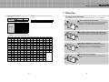
7.2 About Plasma display panel
8.1 DVD/DTV
The followings are phenomena caused by characteristics of the plasma display panel.
Since it is not a fault, you may continue to use the product.
Resolution
Aspect Ratio
480i
720 x 480
16:9
480p
720 x 480
16:9
Black or twinkling spots on the screen
576i
720 x 576
16:9
Although the plasma display panel is manufactured with high-precision
technology, there may exist black or twinkling spots on the screen.
Since it is not a fault, you may continue to use the product.
720p
1280 x 720
16:9
1080i
1920 x 1080
16:9
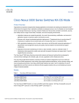
8.2 PC & DVI
Afterimage
Resolution
V-Freq. (Hz)
H-Freq. (KHz)
640x350
85
37.86
60
31.47
72
37.86
75
37.50
85
43.27
56
35.16
60
37.88
72
48.08
75
46.88
85
53.67
60
31.50
60
48.36
70
56.48
75
60.03
85
68.68
1152 x 864
75
67.50
1280 x 960
60
60.00
1280 x 1024
60
63.98
1280 x 768
60
47.69
1366 x 768
60
47.69
1600 x 1200
60
75.00
When you keep static image still for around 3 hours, an afterimage
may occur. In this case, the afterimage can be slowly removed when
operating the screen with full white test pattern.(refer to page 33)
640 x 480
Noise from the inside
800 x 600
When you turn on the product slight buzzing sound may be heard from
the rear of display panel. Since it is not a fault, you may continue to
use the product.
853 x 480
1024 x 768
41
42
Remarks
Infinitely expandable
9. Specifications
Power supply
Power consumption
Max
Plasma display panel
Contrast ratio
Brightness
Front filter
Number of pixels
Seam gap (In case of multi formation)
Environmental condition
Temperature
Humidity
Signal
Video signal
PC signal
Frequency
Connectors
Video
Component
PC
DVI
Serial
External dimension
100 ~ 240V AC. 50/60Hz
memo
400W
42inch, 16:9 aspect ratio
3,000 :1 (Dark room)
1,000 cd/m2 (w/o Film)
Low reflection coating film
853W X 480H Pixels
5mm
0°C~ 35°C
20% ~ 70%
NTSC, PAL, SECAM,
VGA, SVGA, WVGA, XGA, SXGA, WXGA, UXGA
Horizontal Frequency 15.5 ~75kHz
Vertical Frequency 50~ 85Hz
Input
Output
CVBS : BNC
S-Video : DIN 4pin
Y, Pb, Pr : BNC
Same as left side
PC RGB : D-Sub 15pin
TMDS : DVI-D 24pin
RS-232C D-sub 9pin(female)
RS-232C D-sub 9pin (male)
926.2mm[W] X 523.6mm[H] X76.5mm[D]
926.2
76.5
528.9
93.8
RS-232C OUT
RS-232C IN
VIDEO
IN
OUT
S-VIDEO
IN
OUT
COMPONENT
OUT
IN
523.6
336.0
PC
IN
DVI-D OUT
OUT
DVI-D IN
AC INPUT
93.8
Weight
27 kg
43
44
Multi-PDP
Infinitely expandable
memo
memo
45
46
Multi-PDP