1
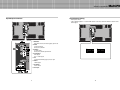
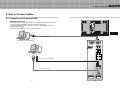
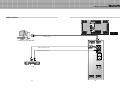
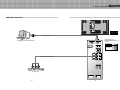
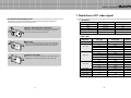
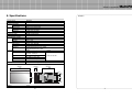
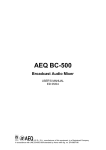
A revolutionary multi PDP
Infinitely expandable multi PDP
Multi-PDP
Multi-PDP User’s Manual
Thank you for your purchasing our Multi-PDP.
Please read through this user's manual for safety before installing this product.
This product is manufactured for Multi Plasma display model only.
Infinitely expandable
Multi-PDP
Contents
Features of Multi-PDP
You can enjoy a wide full-flat screen with high brightness and high quality.
It is installable and movable anywhere thanks to its thin shape.
You can enjoy your favorite programs with various screen-split features
simultaneously presenting several programs.
1. How to keep safely
2. How to install
3~4
How to move Multi-PDP (short distance)
How to move Multi-PDP (long distance)
Stand type
Wall type
3. Guidance for Users
Input/Output Terminals
Set ID Switch Setting
Thank you for your purchasing our Multi-PDP monitor.
This manual describes how to use the product and notes in use.
Please read the manual carefully before using it.
After reading the manual, keep it with the certificate for you to refer to it
whenever you need.
If you have any question or any problem occurs, please contact to the
provider or the A/S center immediately.
Pausing static picture for around 3 hours may cause an afterimage effect.
If you fail to comply with the regulations for safely
Warning and proper use, fire or injury may be caused.
Notice of users
A-grade device
It is a device designed for business purpose with a safety certificate for electromagnetic
interference, which user should be mindful of.
User’s Manual
Multi-Screen Control
System(MSCS)
Guide Pin(4pcs)
4. How to connect cables
4.1. Connection of one set Multi-PDP
PC & DVI Connection
VCR Connection
DVD & DTV Connection
4.2. Connection of M x N Multi-PDP
4.3. Connection of 3 x 3 Multi-PDP
4.4. Setting ID of M x N Multi-PDP
Power Cable
1
11
13
15
17~18
19
20
5. Setting and operation of MSCS
5.1 Set ‘Com Port’ for Communication
5.2 Set ‘Multi Screen’
5.3 Configure diverse screens
5.4 Set several screens at a time
5.5 Use PDP Control
5.6 Slider Control
5.7 Image Adjustment - Graphics & Video
5.8 Orion PDP HOME PAGE
21
22
23
24
25
26~27
28
29
6. Other tips
6.1 Before considering as a failure
6.2 About Plasma display panel
30
31
7. Resolution of PC & Video signal
7.1 DVD/DTV
7.2 PC & DVI
32
32
33
8. Specifications
PC Cable
5
5
6
7
8
9
10
RS232 Cable
2
Infinitely expandable
Multi-PDP
1. HOW TO KEEP SAFELY
If it operates abnormally, stop using it
immediately.
Do not place any liquid-containing
container on it. If the inside is wet, it
may cause electric shock or fire.
Do not put any foreign material into the
product. It may cause a failure or
shorten the life span.
Do not pull out or hang down the
connection cable. It may damage the
cord to cause fire or electric shock.
Do not lean against the product or keep
it leaned. It may cause injury or failure.
Do not put it at any place with much
humidity, dust, oil, smoke or steam. It
may cause failure.
Please refer to a specialized
construction company for installing
stand or wall mount unit. Otherwise,
damage or injury may be caused.
Do not touch the device when lightning
strikes. Otherwise, electric shock can
be caused.
Do not install it at unstable place.
It may cause injury.
Pull out the power plug by holding the
plug. Otherwise, it may damage the
power cord to cause fire or electric
shock.
If you do not want to use the product for
a long time, keep the power plug
unplugged to save the electricity.
Do not put any heavy object on it.
It may cause failure.
Avoid any action to damage the power
code or power plug. It may cause fire
or electric shock.
Do not pull out the power plug with a
wet hand. It may cause electric shock.
Do not use exceeding ratings of outlet
or extension cords. It may cause
failure.
Install the product on safe and flat
surface.
Do not ride or step on the product It may
cause breakage when fallen down.
When moving it, disconnect the
connecting cable. Otherwise, it may
damage the cable to cause fire or
electric shock.
Do not alter (or disassemble) the
product. It may cause electric shock
since high voltage is flowing inside.
Do not install the product at any place
exposed to direct ray of light or near
any heating device. It may shorten
product’s life span or cause failure.
Do not put candles on the product. If the
liquid flows inside the product. It may
cause electric shock or fire.
Do not touch product’s front surface
with hand. Otherwise, the image quality
can be lowered.
3
Make sure the product is not covered with
any object. If the venting hole is blocked,
the inside temperature may rise to cause
overheating resulting in fire.
4
Infinitely expandable
Multi-PDP
2. HOW TO INSTALL
• The set is installable in diverse ways such as on a wall, or stand etc.
• Install this set only at a location where adequate ventilation is available.
• This set is designed to be mounted either horizontally or vertically.
STAND TYPE (OPTIONAL)
• The set can be installed as shown below. (For further information, refer to the optional 'Stand
Installation and Setup Guide'.)
Do not incline the panel forward.
Attention
PANEL
PANEL
PANEL
Guide Pin
How to move Multi-PDP (short distance)
Stand
Stand
PDP
Handles
1. 2 people hold each handle on product’s
back side
2 people transfer the product with holding the
handle and the front part at the same time.
How to move Multi-PDP (long distance)
Hanger Bolt
Transfer gripe
Install on a Stand
Pedestal mount allowing minimum clearance for adequate ventilation.
Attach the transfer gripe to each side of the
product.
2 people move the product with holding the
gripe at the same time.
5
6
Infinitely expandable
3. Guidance for Users
Front view
WALL TYPE (OPTIONAL)
• The set can be installed on the wall as shown below.
(For further information, refer to the optional ‘Wall Mounting Bracket Installation and Setup Guide'.)
Guide Pin
Back view
Hanger
Hanger
PDP
RS-232C OUT
RS-232C IN
VIDEO
IN
OUT
S-VIDEO
IN
OUT
COMPONENT
OUT
IN
PC
IN
Hanger Bolt
DVI-D OUT
OUT
DVI-D IN
AC INPUT
Mount on the wall
Wall mount allowing minimum clearance for adequate ventilation.
7
8
Multi-PDP
Infinitely expandable
Input/Output Terminals
Multi-PDP
Set ID Switch Setting
• Example of switch
- This is Dyadic System. In case of PDP set ID 1 and ID 9, set the ID switch as shown in the
below figure
RS-232C OUT
RS-232C IN
VIDEO
IN
OUT
S-VIDEO
IN
OUT
COMPONENT
RS-232C OUT
RS-232C IN
VIDEO
IN
OUT
S-VIDEO
OUT
IN
IN
OUT
COMPONENT
PC
IN
DVI-D OUT
OUT
OUT
IN
DVI-D IN
PC
IN
OUT
AC INPUT
DVI-D OUT
DVI-D IN
AC INPUT
1. RS-232C
Multi-PDP Control, Firmware Upgrade, 9pin D-sub
2.Video
Composite Signal
NTSC, PAL, SECAM
ON
ON
3.S-Video
S-Video Signal
NTSC, PAL, SECAM, 4pin Mini Din
Pr
Pb
1 2 3 4 5 6 7 8
1 2 3 4 5 6 7 8
[PDP ID 1]
[PDP ID 9]
4.Component
DVD Signal
DTV - YPbPr Signal
Y
5. PC
Computer RGB Analog Signal, D-sub 15pin
6. DVI-D
TMDS Signal
7. ID Switch
Set ID Switch
8. AC Input
9
10
Infinitely expandable
Multi-PDP
4. How to Connect Cables
4.1. Connection of one set multi-PDP
PC & DVI Connection
• MSCS (Multi-Screen Control System) that we supply and RS-232C of PDP monitor can
control all functions of Multi-PDP, such as On/Off and screen control.
• To control Multi-PDP through PC, the Identity number of each Multi-PDP and that of
MSCS should be identical.
• RS-232C of each Multi-PDP and PC should be connected.
RS-232C OUT
RS-232C IN
VIDEO
IN
OUT
S-VIDEO
1 2 3 4 5 6 7 8
IN
OUT
COMPONENT
OUT
IN
PC
IN
DVI-D OUT
OUT
DVI-D IN
AC INPUT
1 2 3 4 5 6 7 8
RS-232C COM1
PC (MSCS) to control Multi-PDP
RS-232C OUT
RS-232C IN
VIDEO
1 2 3 4 5 6 7 8
IN
OUT
S-VIDEO
IN
OUT
COMPONENT
Pr
PC
Pb
Y
When connecting to PC-ANALOG
OUT
IN
PC
When connecting to DVI
IN
DVI-D OUT
11
OUT
DVI-D IN
12
Infinitely expandable
Multi-PDP
VCR Connection
RS-232C OUT
RS-232C IN
VIDEO
IN
OUT
S-VIDEO
1 2 3 4 5 6 7 8
IN
OUT
COMPONENT
OUT
IN
PC
IN
DVI-D OUT
OUT
DVI-D IN
AC INPUT
1 2 3 4 5 6 7 8
RS-232C COM1
PC(MSCS) to control Multi-PDP
RS-232C OUT
RS-232C IN
VIDEO
1 2 3 4 5 6 7 8
IN
When connecting to Video
OUT
S-VIDEO
IN
When connecting to S-Video
OUT
COMPONENT
Pr
Pb
Y
OUT
IN
PC
VCR
IN
DVI-D OUT
13
OUT
DVI-D IN
14
Infinitely expandable
Multi-PDP
DVD & DTV Connection
RS-232C OUT
RS-232C IN
VIDEO
IN
OUT
S-VIDEO
1 2 3 4 5 6 7 8
IN
OUT
COMPONENT
OUT
IN
PC
IN
DVI-D OUT
OUT
DVI-D IN
AC INPUT
1 2 3 4 5 6 7 8
RS-232C COM1
•Component Input ports
PC(MSCS) to control Multi-PDP
RS-232C OUT
RS-232C IN
You can get better image quality by
connecting DVD player to component input
ports as below.
Component ports of
the set
Y
Video output ports
of DVD player
Y Pb Pr
Y B-Y R-Y
Y Cb Cr
Pb
Pr
VIDEO
1 2 3 4 5 6 7 8
IN
OUT
S-VIDEO
IN
OUT
COMPONENT
Pr
Pb
When connecting to Component
Y
OUT
IN
PC
IN
OUT
DVD & DTV
DVI-D OUT
15
DVI-D IN
16
Multi-PDP
Infinitely expandable
4.2. Connection of M x N Multi-PDP
RS-232C OUT
RS-232C IN
RS-232C OUT
RS-232C IN
VIDEO
IN
• When connecting a number of Multi-PDP through Daisy Chain(Link), surrounding noise may
come out to lower the image quality.
IN
IN
IN
IN
IN
PC
IN
DVI-D OUT
• In case of lower image quality, it is advisable to use a distributor that can provide resolution over
UXGA (1600*1200 @ 60Hz).
PC
OUT
IN
DVI-D IN
DVI-D OUT
AC INPUT
RS-232C OUT
RS-232C OUT
IN
IN
IN
OUT
IN
PC
PC
OUT
IN
DVI-D OUT
PC
OUT
IN
DVI-D IN
DVI-D OUT
RS-232C OUT
IN
RS-232C IN
VIDEO
OUT
IN
S-VIDEO
1 2 3 4 5 6 7 8
OUT
IN
OUT
IN
IN
DVI-D OUT
OUT
IN
PC
OUT
DVI-D IN
OUT
COMPONENT
OUT
IN
OUT
S-VIDEO
1 2 3 4 5 6 7 8
OUT
COMPONENT
PC
IN
DVI-D OUT
RS-232C OUT
VIDEO
OUT
COMPONENT
IN
AC INPUT
RS-232C IN
VIDEO
S-VIDEO
IN
OUT
DVI-D IN
AC INPUT
RS-232C IN
IN
OUT
IN
AC INPUT
RS-232C OUT
OUT
COMPONENT
OUT
IN
OUT
S-VIDEO
1 2 3 4 5 6 7 8
OUT
COMPONENT
DVI-D IN
1 2 3 4 5 6 7 8
RS-232C IN
VIDEO
OUT
S-VIDEO
1 2 3 4 5 6 7 8
OUT
IN
DVI-D OUT
RS-232C OUT
VIDEO
OUT
COMPONENT
IN
AC INPUT
RS-232C IN
VIDEO
S-VIDEO
IN
OUT
DVI-D IN
AC INPUT
RS-232C IN
IN
OUT
IN
PC
OUT
DVI-D IN
1 2 3 4 5 6 7 8
OUT
COMPONENT
OUT
IN
OUT
S-VIDEO
1 2 3 4 5 6 7 8
OUT
COMPONENT
OUT
IN
DVI-D OUT
RS-232C IN
VIDEO
OUT
S-VIDEO
1 2 3 4 5 6 7 8
OUT
COMPONENT
IN
RS-232C OUT
VIDEO
OUT
S-VIDEO
1 2 3 4 5 6 7 8
PC
OUT
IN
DVI-D IN
DVI-D OUT
AC INPUT
AC INPUT
OUT
DVI-D IN
AC INPUT
RS-232C COM1
PC (MSCS) to control Multi-PDP
RS-232C OUT
RS-232C IN
RS-232C OUT
RS-232C IN
VIDEO
1 2 3 4 5 6 7 8
OUT
OUT
IN
RS-232C IN
OUT
IN
RS-232C IN
OUT
IN
RS-232C IN
OUT
IN
RS-232C IN
IN
RS-232C IN
VIDEO
1 2 3 4 5 6 7 8
OUT
IN
S-VIDEO
OUT
RS-232C OUT
VIDEO
1 2 3 4 5 6 7 8
IN
S-VIDEO
OUT
RS-232C OUT
VIDEO
1 2 3 4 5 6 7 8
IN
S-VIDEO
OUT
RS-232C OUT
VIDEO
1 2 3 4 5 6 7 8
IN
S-VIDEO
OUT
RS-232C OUT
VIDEO
1 2 3 4 5 6 7 8
IN
S-VIDEO
OUT
RS-232C OUT
VIDEO
1 2 3 4 5 6 7 8
IN
S-VIDEO
IN
RS-232C IN
VIDEO
1 2 3 4 5 6 7 8
IN
RS-232C OUT
OUT
IN
S-VIDEO
OUT
IN
OUT
S-VIDEO
OUT
IN
OUT
COMPONENT
COMPONENT
COMPONENT
COMPONENT
COMPONENT
COMPONENT
COMPONENT
COMPONENT
Pr
Pr
Pr
Pr
Pr
Pr
Pr
Pr
Pb
Pb
Pb
Pb
Pb
Pb
Pb
Pb
S-VIDEO
Y
Y
OUT
IN
PC
IN
Y
OUT
IN
PC
OUT
IN
Y
OUT
IN
PC
OUT
IN
Y
OUT
IN
PC
OUT
IN
Y
OUT
IN
PC
OUT
IN
Y
OUT
IN
PC
OUT
IN
Y
OUT
IN
PC
OUT
IN
OUT
IN
PC
OUT
IN
OUT
PC
DVI-D OUT
PDP1
17
DVI-D IN
DVI-D OUT
PDP2
DVI-D IN
DVI-D OUT
PDP3
DVI-D IN
DVI-D OUT
DVI-D IN
PDP4
DVI-D OUT
DVI-D IN
PDP5
DVI-D OUT
DVI-D IN
PDP6
18
DVI-D OUT
DVI-D IN
PDP7
DVI-D OUT
PDP8
DVI-D IN
Infinitely expandable
4.3. Connection of 3 x 3 Multi-PDP
ID 1
4.4. Setting ID of M x N Multi-PDP
ID 2
RS-232C OUT
PC
RS-232C IN
IN
PC
RS-232C IN
OUT
ID 4
IN
RS-232C OUT
PC
RS-232C IN
IN
PC
RS-232C IN
OUT
IN
RS-232C OUT
PC
RS-232C IN
IN
OUT
PC
RS-232C IN
OUT
ID 8
RS-232C OUT
IN
ID 6
RS-232C OUT
ID 7
PC
RS-232C IN
OUT
ID 5
RS-232C OUT
• Identity number (ID) indicates the location of each Multi-PDP.
• When you look at the Multi-PDP screens in front of Multi-PDP.
ID 3
RS-232C OUT
IN
PC
RS-232C IN
OUT
IN
RS-232C OUT
PC
RS-232C IN
OUT
IN
PDP ID
1
PDP ID
2
PDP ID
3
PDP ID
4
PDP ID
5
PDP ID
6
PDP ID
7
PDP ID
8
PDP ID
9
PDP ID
10
PDP ID
11
PDP ID
12
PDP ID
13
PDP ID
14
PDP ID
15
PDP ID
16
PDP ID
17
PDP ID
18
PDP ID
19
PDP ID
20
PDP ID
21
PDP ID
22
PDP ID
23
PDP ID
24
PDP ID
25
OUT
ID 9
RS-232C OUT
Multi-PDP
OUT
Recommended ID of M x N screens
PC Signal Distributor
(UXGA : over 250MHz)
ID 1
1 2 3 4 5 6 7 8
ID 6
1 2 3 4 5 6 7 8
ID 11
1 2 3 4 5 6 7 8
ID 16
1 2 3 4 5 6 7 8
ID 21
PC
RS-232C control PC
19
1 2 3 4 5 6 7 8
ID 2
1 2 3 4 5 6 7 8
ID 7
1 2 3 4 5 6 7 8
ID 12
1 2 3 4 5 6 7 8
ID 17
1 2 3 4 5 6 7 8
ID 22
1 2 3 4 5 6 7 8
ID 3
1 2 3 4 5 6 7 8
ID 8
1 2 3 4 5 6 7 8
ID 13
1 2 3 4 5 6 7 8
ID 18
1 2 3 4 5 6 7 8
ID 23
1 2 3 4 5 6 7 8
20
ID 4
1 2 3 4 5 6 7 8
ID 9
1 2 3 4 5 6 7 8
ID 14
1 2 3 4 5 6 7 8
ID 19
1 2 3 4 5 6 7 8
ID 24
1 2 3 4 5 6 7 8
ID 5
1 2 3 4 5 6 7 8
ID 10
1 2 3 4 5 6 7 8
ID 15
1 2 3 4 5 6 7 8
ID 20
1 2 3 4 5 6 7 8
ID 25
1 2 3 4 5 6 7 8
Infinitely expandable
Multi-PDP
5. Setting and operation of MSCS
• Activate MSCS.exe file.
5.2 Set ‘Multi-Screen’
Set Multi Screen
total number of connected Multi-PDP sets.
1 Select
-In case the number is 9, set the Total Screen at “9”.
an arrangement way in ‘Select M X N’
2 Select
-Select a desirable arrangement way among 1*9, 3*3, and 9*1. (The arrangement
way is displayed depending on the total number of connections.)
the Input Source, and press the Play button .
3 Select
-Select a connected external Input Source, and press the ‘Play’ button.
MSCS (Multi-Screen Control System) Main Image
-The overall screen is played on the selected external unit if pressing the “Play”
button.
5.1 Set ‘Com Port’ for Communication
• Connect Multi-PDP RS-232C and PC Com Port
Com Port Setting
• Port is available from Com1 to Com5.
• Make sure that Baud Rate is set at 115200.
• When ‘PORT’ and ‘Baud Rate’ is set, click “Connect”.
21
22
Infinitely expandable
5.3 Configure diverse screens
5.4 Set several screens at a time
• You can configure diverse screens as you want.
• You can configure diverse screens as you want.
a desirable Input Source in “Select Input”
1 Select
Ex) Select “DVI” in “Select Input”
a desirable Input Source in “Select input”.
1 Select
-Select a desirable ‘DVI’ in “Select Input”
a desirable screen in ‘Screen Configuration’.
2 Click
-Left-click a screen which should be converted to DVI.
a desirable screen in “Screen Configuration”
2 Click
-Left-click and drag on a start screen
-The screen you selected will be changed into DVI.
can configure other screens in the same way.
3 You
-Selected screen will be displayed in DVD.
23
screen is divided for display.
3 The
-The selected screen will be displayed in DVI.
24
Multi-PDP
Infinitely expandable
5.5 Use “PDP Control”
5.6 Slide Control
• Transmit PDP Control Data to selected ID of M-PDP.
• If checking ‘all M-PDP” box, the Data will be sent to all connected M-PDP, disregarding PDP ID.
• Set the slide show list as you want. It can be repeated.
Multi-PDP
a desirable screen arrangement in Screen Configurations.
1 Select
-Select a desirable screen arrangement and input source.
•
If pressing the Auto Tracking Set button, the Input Source executes command only in PC.
-After operating Auto Tracking Set command, If alignment does not fit, give Auto Tracking
Detail command to control Frequency, Phase, Line Start Pixel Start in detail.
playing time in Slide Control.
2 Input
-Input display time and save the data by pressing the Add button.
Adjusting steps are as follows;
1) Adjust “Phase” until you can have clear vertical lines.
2) After adjusting “Phase”, adjust “Linestart” to fit vertical alignment, “Pixelstart” for horizontal
alignment.
3) Adjust “Frequency”, if you still have wrong alignment.
If you adjust “Frequency”, repeat step 1) and 2) to fit alignment.
-The range where you can adjust is from -50 to 50.
diverse screen arrangements in the same way.
3 Save
-Set diverse types of display screen.
• The Selected PDP ID indicates activated PDP ID in Screen Configuration
(red rectangular area)
25
26
Infinitely expandable
Multi-PDP
5.7 Image Adjustment - Graphics & Video
4 -When pressing the Start button, the saved screen arrangement is automatically
a Input source for image adjustment.
1 Select
-Select a PC to control PC screen.
-Click the White Balance button.
displayed for preset time.
& Video Dialog is displayed.
2 Graphic
-You can adjust the image on the below screen.
checking the Repeat Slide box, the display is repeated unless
5 When
pressing the Stop button.
6 Press the Stop button to discontinue the Slide.
3 Press the Reset button to initialize all Image Adjustment values.
• All M-PDP command is executable only in the User Mode and Test Pattern.
• Delete: Select a Slideshow that you want to delete and click Delete.
• Delete ALL: Delete all slide shows.
• Delay Time: Time gap between slide shows.
-The time gap is selectable from 10 seconds to 59 minutes and 59 seconds
• Press the Red, White, Green, Black or Blue button to activate the Test Pattern as an
internal pattern.
• Press the Black button to end the internal pattern. The test pattern is activated as
preset, even after powering off and on again.
• You can save adjusted values in each mode into the hard disk by pressing the Save
button. In case data is deleted by mistake during adjustment, you can call up the
saved file by pressing the Lode button.
27
28
Infinitely expandable
Multi-PDP
6. Other tips
5.8 Orion PDP HOME PAGE
6.1 Before considering as a failure
Before calling for any repair, check the following and then refer to a near A/S center.
• If you are in connection with the Internet, you can reach our URL clicking Help and Orion
PDP Home Page.
“Tick” sound from the main body.
If there is no problem with the screen or sound, the “tick” sound is likely
to result from the cabinet lightly shrinking with the change of room
temperature. The sound does not affect product’s performance.
Orion PDP HOME PAGE
No image at upper and bottom part of the screen.
As for a screen which is over 16:9 in width (such as cinema-sized one),
no image may be displayed at upper and bottom part of the screen.
Speckles or white lines on the screen
Check whether the problem is caused by vehicle, streetcar, highvoltage cable or neon sign, which emitting interference wave or
electromagnetic induction. Avoid any interfering object.
Screen size can be changed.
The screen size may be fitted to the first dark scene depending on
contents.
29
30
Infinitely expandable
Multi-PDP
7. Resolution of PC video signal
6.2 About Plasma display panel
7.1 DVD/DTV
The followings are phenomena caused by characteristics of the plasma display panel.
Since it is not any failure, you may use it at rest.
Resolution
Aspect Ratio
480i
720 x 480
16:9
480p
720 x 480
16:9
Black or twinkling spots on the screen
576i
720 x 576
16:9
Although the plasma display panel is manufactured with high-precision
technology, there may exist black or twinkling spots on the screen.
Since it is not any failure, you may use it at rest.
720p
1280 x 720
16:9
1080i
1920 x 1080
16:9
7.2 PC & DVI
Afterimage
Resolution
V-Freq. (Hz)
H-Freq. (KHz)
640x350
85
37.86
60
31.47
72
37.86
75
37.50
85
43.27
56
35.16
60
37.88
72
48.08
75
46.88
85
53.67
60
48.36
70
56.48
75
60.03
85
68.68
1152 x 864
75
67.50
1280 x 960
60
60.00
1280 x 1024
60
63.98
1600 x 1200
60
75.00
When you keep static image still for around 3 hours, an afterimage
may occur. In this case, the afterimage can be slowly removed when
operating the screen with full white test pattern.(refer to page 28)
640 x 480
Noise from the inside
800 x 600
When you turn on the product, driving sound may be heard from the
display panel. Since it is not any failure, you may use it at rest.
1024 x 768
31
32
Remarks
Infinitely expandable
memo
8. Specifications
Product name
Power supply
Power consumption
Max
Plasma display panel
Contrast ratio
Brightness
Front filter
Number of pixels
Seam gap (In case of multi formation)
Environmental condition
Temperature
Humidity
Signal
Video signal
PC signal
Frequency
Connectors
Video
Component
PC
DVI
Serial
Option
External dimension
MIS-4201
100 ~ 240V AC. 50/60Hz
400W
42inch, 16:9 aspect ratio
3,000 :1 (Dark room)
1,000 cd/m2 (w/o Film)
Low reflection coating film
853W X 480H Pixels
5mm
0°C~ 35°C
20% ~ 70%
NTSC, PAL, SECAM,
VGA, SVG A, XGA, SXGA, UXGA
Horizontal Frequency 15.5 ~75kHz
Vertical Frequency 50~ 75Hz
Input
Output
CVBS : BNC
S-Video : DIN 4pin
Y, Pb, Pr : BNC
Same as left side
PC RGB : D-Sub 15pin
TMDS : DVI-D 24pin
RS-232C D-sub 9pin(female)
RS-232C D-sub 9pin (male)
Stand, Wall Mounting Bracket , Signal Cable
926mm[W] X 523mm[H] X76.5mm[D]
926
76.5
528.87
93.8
RS-232C OUT
RS-232C IN
VIDEO
IN
OUT
S-VIDEO
1 2 3 4 5 6 7 8
IN
OUT
COMPONENT
OUT
IN
523
336
PC
IN
DVI-D OUT
OUT
DVI-D IN
AC INPUT
93.8
Weight
27 kg
33
34
Multi-PDP