1
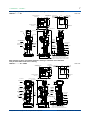
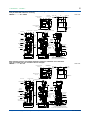
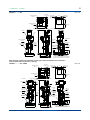
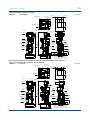
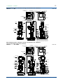
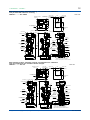
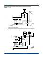
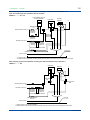
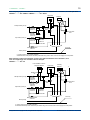
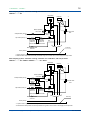
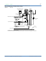
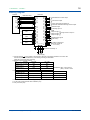
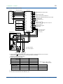
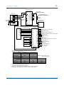
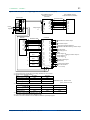
<<Contents>> <<Index>> General Specifications Model TB400G Surface Scattering Light Turbidity Meter GS 12E04A02-01E nGeneral There have been increasing demands for both industrial use and portable water of good quality because of rapid industrial development and the betterment of consumers’ everyday life. A large amount of the waste water from both kinds of uses has been drained or discharged into rivers, causing pollution to worsen year after year. This raises a serious social problem. Therefore, turbidity meters, conventionally used for the operation and control of a water purification plant, are nowadays being required to measure the amount of matter suspended in various sorts of industrial waste water and to detect the turbidity of chemical processes. Since their sales began in 1959, Yokogawa’s processuse turbidity meters, centering on the area of water supply, have achieved a number of records and have provided high reliability to many users. The TB400G Surface Scattering Light Turbidity Meter has a microprocessor to provide intelligent features for advanced performance and high reliability. nSystem Configuration For example, the diagram below is a system with automatic cleaning and automatic zero calibration nFeatures l Equipped with a microprocessor, allowing provision of advanced performance and high reliability. l Enhanced self-testing functions such as detection of a disconnected lamp, a converter check, and upper and lower limit alarms. l Provided with multiple functions such as automatic zero calibration. l Compact and light weight. The system allows access from the front, offering easy maintenance. l Use of surface scattering-light measuring method eliminates the measurement errors caused by contamination on the cell port. l Signal smoothing as a measure against air bubbles in sample water. l pH meter or free available chlorine analyzer can be installed on the TB400G. Converter 4-20 mA DC or 1-5 V DC Head tank Detector Zero-turbidity filter Tap water *1 *1: Drain Sample water F01.ai Reverse flow of tap water should be prevented using with a check valve on the supply line of tap water. Yokogawa Electric Corporation 2-9-32, Nakacho, Musashino-shi, Tokyo, 180-8750 Japan Tel.: 81-422-52-5617 Fax.: 81-422-52-6792 GS 12E04A02-01E ©Copyright Feb. 1995 7th Edition Nov. 2014 2 <<Contents>> <<Index>> nStandard Specifications Measurement: Turbidity of tap water, river water, and water used in general processes Measurement method: Surface scattering-light measurement Measuring range: 0-2 to 0-2000 mg/L Display: Four-digit LED display (resolution; 0.01 mg/L, maximum display value; 2200 mg/L) Display Units: “mg/L” (standard) or “ ” (selectable) Note: In this GS, the unit “liter” is described as “L”. Real display unit is “mg/l”. The unit “ ” means degree. Output Range: 3 range switching Remote or local (default) range switching, selectable Auto or manual (default) range,selectable For auto range, changeover point is user configurable. 3 ranges are user configurable. The span should be 20% or more of the upper range limit or 2 mg/L (default), whichever is greater. Analog Output Signal: 4 to 20 mA DC (maximum load resistance: 550 Ω) or 1 to 5 V DC (output resistance: 100 Ω or less) Digital Output Signal: RS-232C (turbidity signal, under-maintenance signal, error signal, calibrating signal, and range signal) Contact Output: Maintenance output (during maintenance) Failure output (if an error is detected) Range output (corresponding to the output range selected) (common to COM) Configurable contact pair for (a) high and low alarm limits or (b) auto-calibration signal or (c) auto-cleaning signal Contact status: Type of contact output Power off Power on *1 Not in Action In Action Closed Open Closed Open Closed Open High/low alarm Closed Closed Open Auto zero calibration/cleaning Closed Open Closed Maintenance Fail *1: Contact status (open/closed) when power is turned on is user configurable. Contact Rating: Maximum opening/closing voltage: 250 V AC or 220 V DC (resistive load) Maximum application current: 2 A AC or 2 A DC (resistive load) Maximum opening/closing rating: 120 VA or 60 W (resistive load) Contact Input: Remote range switching (common to COM) Input resistance when on: 200 Ω or less Input resistance when off: 100 kΩ or more Automatic Cleaning: Water jet cleaning (with configurable time cycles) Automatic Calibration: Zero-point calibration using zero turbidity reference water (for a system with automatic cleaning and calibration) All Rights Reserved. Copyright © 1995, Yokogawa Electric Corporation Error Detection: Turbidity over-range, disconnection of lamp wiring, error in lamp voltage, error in the AD circuit, memory error, CPU error Check Function: Converter operation check Manual Calibration: Zero calibration: Using zero-turbidity reference water or with light source set to off (selectable) Span calibration: Using a calibration plate Other Functions: Breakpoint line-segment output, upper and lower limit alarms Material: Detector: Modified black PPE (wetted parts) Piping: Hard PVC, polyethylene resin, and polypropylene resin (all for wetted parts) Stanchion:Carbon steel or stainless steel Converter:Aluminum alloy casting Paint: Converter:Baked polyurethane resin finish color; Munsell 0.6GY3.1/2.0 and Munsell 2.5Y8.4/1.2 Stanchion;Baked polyurethane resin finish color; Munsell 0.6GY3.1/2.1 Ambient temperature: -5 to 50°C (sample and tap water may need protection against freezing) Ambient humidity: 5 to 95%RH (non-condensing) Storage temperature: -30 to 70°C Installation location: Indoor (weather protection is required for outdoor installation) Installation: Separate detector and converter; Pipe- or rack-mounted System with sampling system; Fixed with anchor bolts Piping Connections: System with sampling system; VP40 for drain VP16 for other purposes System without sampling system; 25 mm ID hose joint Cable Inlet: 5 cable glands (on the bottom of the converter) Outer diameter of applicable wires: 6 to 12 mm (9 to 11 mm when with arrester option) Wiring type: Power, analog output, digital output, contact output, contact input (for grounding, GROUND on the connection terminals of the converter or the ground terminal on the outside of the case should be used) Power supply: 100/110 V AC, 50/60 Hz, 200/220 V AC, 50/60 Hz Noise filter assembly: (only for TB400G-□-□-KC) Ambient temperature: -10 to 50°C (no dew condensation allowed) Storage temperature: -25 to 70°C Construction: JIS C 0920 Watertight (IP53) Power Consumption: Detector and converter:50 VA or less, respectively With sampling system: 200 VA or less (in full specifications, excluding combination instruments) Automatic Cleaning Function: Water jet cleaning. Cleaning time and interval are user configurable. (When auto cleaning is specified) GS 12E04A02-01E 7th Edition Jan. 16, 2015-02 3 <<Contents>> <<Index>> Automatic Zero Calibration Function: Zero point calibration using zero turbidity water (when auto cleaning/zero calibration is specified) Weight: Detector; Approx. 3 kg Converter; Approx. 9 kg With sampling system; Approx. 50 kg (in full specifications, excluding combination instruments) Dimensions: Detector: 245 (W) x 250 (H) x 200 (D) mm Converter: 260 (W) x 340 (H) x 150 (D) mm With stanchion: 530 (W) x 1450 (H) x 550 (D) mm Sample water: With sampling system: Flow rate: 2 to 10 L/min Pressure: 20 to 500 kPa Temperature: 0 to 50°C (ambient temperature should not exceed 30°C) Without sampling system: Flow rate: 1.5 to 2 L/min Temperature: 0 to 50°C (Ambient temperature should not exceed 30°C) Zero turbidity water and cleaning water (tap water): Turbidity: 2 mg/L or less Temperature: 0 to 50°C (Ambient temperature should not exceed 30°C) Pressure: 100 to 500 kPa Flow rate: Zero turbidity water: 2 to 10 L/min Cleaning water: 3 to 6 L/min Consumption: Zero turbidity water: Approx. 380 L/day (at a flow rate of 2 L/min) Cleaning water: Approx. 90 L/min (at a flow rate of 3 L/min) (when auto cleaning/zero calibration is enabled and time setting is factory default) Automatic cleaning time chart when provided with automatic cleaning, but not automatic zero calibration Example: N (number of cleanings) = 4 Measurement Power on start Cleaning time 1 Cleaning cycle Drain time 1 Water fill time 1 Recovery time ON SV1 (Drain) SV2 (Cleaning) 3 4 OFF HOLD Output holding *1 2 HOLD ON SV1 (Drain) OFF N= 1 SV2 (Cleaning) OFF 3 4 ON ON OFF SV3 (Sample water) ON OFF SV4 (Zero-turbidity reference water) Output holding *1 2 One calibration cycle HOLD ON OFF Calculation for zero calibration *1: During calibration, output is always held. F03.ai Default values as shipped from factory: Cleaning cycle: 2 hours Cleaning time 2: 30 sec Drain time 2: 0 sec Water fill time 2: 100 sec Recovery time: 150 sec nCharacteristics Linearity (when using kaolin standard): Upper range limit of 1000 mg/L or less; ±2% of upper range limit Upper range limit of 2000 mg/L or less; ±5% of upper range limit Linearity (when using polystyrene latex standard): Upper range limit of 100 mg/L or less; ±2% of upper range limit Repeatability: Standard solution; 2 % of upper range limit Supply voltage effects: ± 1 % of upper range limit / within ± 10 % of rated voltage Ambient temperature effects: ± 1 % of upper range limit / 10°C (when using calibration plate) Response time: 2 minutes or less (90 % response, with a sampling system, flow rate of 3 L/min) Warm-up time: Approx. 30 minutes Regulatory Compliance (for TB400G-□-□-KC) Korea Electromagnetic Conformity Standard Class A 한국 전자파적합성 기준 OFF N= 1 ON Calibration start Drain time 2 Drain time 2 Recovery time Water fill Water fill time 2 time 2 Water fill time 2 Recovery Cleaning time 2 time ON One cleaning cycle OFF *1: During cleaning process, output is always held. F02.ai Default Values as shipped from factory: Cleaning cycle: 2 hours Cleaning time 1: 30 sec Drain time 1: 10 sec Water fill time 1: 100 sec Recovery time: 150 sec Automatic zero calibration time chart when provided with automatic cleaning and automatic zero calibration Example: N (number of cleanings) = 4 All Rights Reserved. Copyright © 1995, Yokogawa Electric Corporation GS 12E04A02-01E 7th Edition Nov. 14, 2014-00 4 <<Contents>> <<Index>> nModel and Codes [Style: S3] Model Suffix Code TB400G .................................... Output -4 -5 -1 -3 Power supply -6 -7 Device -NN configuration and -A1 Application -A2 -A3 -KC Optional Mounting bracket specification Piping Stanchion material Bubble treatment Tag plate Description Option Code ................ ................ ................ ................ ................ ................ ................ ................ ................ ................ ................ ................ /P /R /B /S /L /SCT Combination analyzer /PHN5 /PHU5 /FC Arrester /ARS PSL calibration /PSL Surface Scattering Light Turbidity Meter 4 to 20 mA DC 1 to 5 V DC 100 V AC, 50/60 Hz 110 V AC, 50/60 Hz 200 V AC, 50/60 Hz 220 V AC, 50/60 Hz Without sampling system, automatic cleaning, or automatic zero calibration *1 With sampling system, but without automatic cleaning or automatic zero calibration With sampling system and automatic cleaning, but without automatic zero calibration With sampling system, automatic cleaning, and automatic zero calibration For Korea. Without sampling system. (without cleaning,without auto.zero calibration) *8 Mounting bracket: For pipe mounting *2 Mounting bracket: For rack mounting *2 Tie-in with rear piping *3 Stainless steel stanchion *3 Bubble retardant for low range *3 *4 Stainless steel tag plate With PH450G pH meter (without ultrasonic cleaning) *3 *5 With PH450G pH meter (with ultrasonic cleaning) *3 *5 With non-reagent type free available chlorine analyzer *3 *5 With arrester *6 Calibration using polystyrene latex *7 *1: *2: *3: *4: A de-foaming tank (head tank) is to be provided. It is to be installed to adjust the sample flow to the detector at 1.5 to 2 L/min. These options are available for the specification of “without sampling system” (suffix code: -NN, -KC). These options are available for the specification of “with sampling system” (suffix code: -A1, -A2 or -A3). When measuring range is low (200 mg/L or less) and if air bubbles are likely to be formed on the sample, this option is to be specified. When measuring range is high (more than 200 mg/L), this option is not to be specified. Because air bubbles in high ranges don’t disturb the measurement, and because clogging or reduction of flow rate may occur at the removal port of air bubbles on the flow line. *5: A pH meter with necessary units, or non-reagent type free available chlorine analyzer should be purchased separately. Both of a pH meter and non-reagent type free available chlorine analyzer can not be installed together on the TB400G. Available model & suffix codes are as follows; Non-reagent type free available chlorine analyzer (refer to the GS 12F5A1-E) FC400G-□-□*A/ST (for /FC) * The power supply of FC400G is to be suitable for the power supply of TB400G. pH meter (refer to the GS 12B07B02-E, GS 12J05C02-00E and GS 12B07C05-01E) pH sensor PH8EFP-03-TN-TT1-N-G*A (for /PHN5 and /PHU5) pH holder PH8HF-PP-JPT-T-NN-NN*A (without cleaning) (for /PHN5) PH8HF-PP-JPT-T-S3-C1*A (with ultrasonic cleaning) (for /PHU5) pH converter PH450G-A-J (for /PHN5 and /PHU5) Ultrasonic oscillator PUS400G-NN-NN-□-J * The power supply of PUS400G is to be suitable for the power supply of TB400G. *6: This option is not available for the options of /PHN5, /PHU5 or /FC. *7: Polystyrene latex solution of which concentration is 2 degrees is used as a standard solution to calibrate the TB400G. Without this option, the standard TB400G is calibrated with a Kaolin solution. *8: No additional specifications other than “/P”,”/R” and “/SCT” can be chosen. Accessories Item Quantity Standard calibration plate 1 Silicone cloth 1 Lamp 1 Fuse 4 each Description Housed in the converter As a spare 1 A and 3 A (as spares) Pipe mounting bracket (optional) 1 set When specifying option code "/P" Rack mounting bracket (optional) 1 set When specifying option code "/R" Soft PVC tube, 1 m 2 For detector piping (for without sampling system) Clamp 2 For detector piping (for without sampling system) All Rights Reserved. Copyright © 1995, Yokogawa Electric Corporation GS 12E04A02-01E 7th Edition Nov. 14, 2014-00 5 <<Contents>> <<Index>> Spare Parts Item Lamp 1*: Part Number Recommended Replacement Interval 1* K9410DA Yearly Filter, 1 μm K9008ZD Yearly Filter, 0.2 μm (when specifying option of “/PSL”) K9726EH Yearly Fuse, 1 A A1109EF Yearly Fuse, 3 A A1113EF Yearly Drain tube (when specifying suffix of “-A2” or “-A3”) K9411JM Yearly Replacement intervals vary depending on the application. All Rights Reserved. Copyright © 1995, Yokogawa Electric Corporation GS 12E04A02-01E 7th Edition Nov. 14, 2014-00 6 <<Contents>> <<Index>> nExternal Dimensions Without sampling system TB400G - □ - □ - NN, TB400G - □ - □ - KCUnit: mm Converter 56 Detector 202 310 250 340 2B pipe (Ø60.5) 245 208 (30) 150 2B pipe (Ø60.5) Pipe mounting bracket Pipe mounting bracket (Option code: /P) 260 158 150 Cable inlet (Ø6 to Ø12 o.d. waterproof plug) 48 Sample water output 170 145 Sample water input Ø25 i.d. hose joint Ø25 i.d. hose joint Rack mounting bracket 120 (Option code: /P) Rack mounting bracket (Option code: /R) ● 33 150 105 126.5 (Option code: /R) 25 4-Ø6 holes 238 Dedicated cable Noise filter assembly for TB400G - □ - □ - KC 275 10 190 170 3-Ø6 holes Unit: mm 92 4-M5 screws Mounting bracket for noise filter assembly 70 4-ø5.5 holes External power cable inlet (cable OD of Ø6 to Ø12) 20 50 160 75 203 17 10 30 2-M5 screws 10 30 110 130 Dedicated power cable outlet 4-ø6.5 holes Weight: Approx. 0.7 kg 36 Dedicated power cable for noise filter assembly 152 Black L1 White L2 Green G L1 Black Approx. 80 Cable length : Approx. 0.7 m Weight of noise filter assembly: Approx. 2 kg Approx. 80 L2 White G Green Weight of power cable: Approx. 0.2 kg Panel mounting bracket for noise filter assembly (Option code: /P) 4-M5 screw Weight: Approx. 0.7 kg 5- Ø6.5 holes 8 70 75 Ø6.5 x 13 hole 200±0.5 2- Ø5.5 holes U-bolt 15 35 35 2-Ø9 holes M8 nut ×2 70 100 4-Ø10 holes 2-inch pipe (vertical mounting OD Ø60.5) (10) All Rights Reserved. Copyright © 1995, Yokogawa Electric Corporation (92) 54 GS 12E04A02-01E 7th Edition Nov. 14, 2014-00 7 <<Contents>> <<Index>> With sampling system, but without automatic cleaning or automatic zero calibration TB400G - □ - □ - A1 Unit: mm 4-ø15 Holes for anchor bolts Approx. 200 Maintenance space 600 20 Cabinet Front Approx. 500 350 100 Manually operated valve V3 ( 20 ) 490 Approx. 200 530 Maintenance space (100) Manually operated valve V2 Maintenance space Terminal box *3 Converter Detector *2 Manually operated valve V5 1450 1475 *2 Drainage port VP40 pipe Manually operated valve V1 Sample water inlet VP16 pipe 530 150 70 385 Tap water inlet VP16 pipe 150 93 *1 Zero-turbidity reference filter 80 *1 Manually operated valve V4 250 Head tank 150 *1: Option code /B specified for rear piping. Bottom piping is without /B specified. 550 *2: Option code /L specified for bubble retardant. *3: Option code /ARS specified for with arrester. 50 *1 With sampling system, but without automatic cleaning or automatic zero calibration with pH meter without ultrasonic cleaning TB400G - □ - □ - A1 / PHN5Unit: mm (100 ) Approx. 200 Approx. 500 Cabinet 350 20 Terminal box Approx. 200 Maintenace space 100 Manually operated valve V3 530 Maintenace space 600 4-ø15 Holes for anchor bolts Manually operated valve V2 Front ( 20 ) 490 Maintenace space KCl tank Turbidity converter pH converter Turbidity detector *2 Head tank pH sensor Manually operated valve V4 Manually operated valve V5 *2 Manually operated valve V6 Manually operated valve V1 Zero-turbidity reference filter Drainage port VP40 pipe Tap water inlet VP16 pipe 530 587 70 385 550 50 *1 All Rights Reserved. Copyright © 1995, Yokogawa Electric Corporation 150 93 *1 80 *1 173.5 Sample water inlet VP16 pipe 150 250 1450 Flow-through type holder 150 *1: Option code /B specified for rear piping. Bottom piping is without /B specified. *2: Option code /L specified for bubble retardant. GS 12E04A02-01E 7th Edition Nov. 14, 2014-00 8 <<Contents>> <<Index>> With sampling system, but without automatic cleaning or automatic zero calibration with pH meter with ultrasonic cleaning TB400G - □ - □ - A1 / PHU5 Unit: mm Approx. 200 Maintenance space 600 350 (100 ) Approx. 200 530 Maintenance space Approx. 400 4-ø15 Holes for anchor bolts Manually operated valve V2 Cabinet 20 Terminal box 490 Front ( 20 ) KCl tank pH converter Turbidity converter Approx. 500 100 Manually operated valve V3 Maintenance space Ultrasonic oscillator Turbidity detector *2 Head tank pH sensor Flow-through type holder Manually operated valve V5 1450 *2 Manually operated valve V1 Drainage port VP40 pipe Sample water inlet VP16 pipe Zero-turbidity reference filter 70 550 587 150 150 80 *1 385 530 Tap water inlet VP16 pipe 93 *1 173.5 Manually operated valve V6 250 Manually operated valve V4 150 *1: Option code /B specified for rear piping. Bottom piping is without /B specified. *2: Option code /L specified for bubble retardant. 50 *1 With sampling system, but without automatic cleaning or automatic zero calibration with non-reagent type free available chlorine analyzer TB400G - □ - □ - A1 / FCUnit: mm 490 20 Terminal box 600 Maintenance space Cabinet 100 Manually operated valve V3 Approx. 200 530 Maintenance space 350 (100) Approx. 200 Front (20) Approx. 500 4-ø15 Holes for anchor bolts Manually operated valve V2 Maintenance space Turbidity converter FC400G(converter) Turbidity detector *2 Head tank FC400G (detector) Manually operated valve V5 1450 *2 Manually operated valve V1 Drainage port VP40 pipe Sample water inlet VP16 pipe Tap water inlet VP16 pipe 587 385 80 *1 173.5 530 70 150 150 *1: Option code /B specified for rear piping. Bottom piping is without /B specified. 550 50 *1 All Rights Reserved. Copyright © 1995, Yokogawa Electric Corporation 93 *1 Zero-turbidity reference filter 150 Manually operated valve V6 Manually operated valve V7 250 Manually operated valve V4 *2: Option code /L specified for bubble retardant. GS 12E04A02-01E 7th Edition Nov. 14, 2014-00 9 <<Contents>> <<Index>> 4-ø15 Hoes for anchor bolts Approx.200 Maintenance space Maintenance space Front ( 20 ) 490 Approx. 500 20 600 Cabinet 100 Manually operated valve V3 Approx. 200 530 350 Manually operated valve V2 (100) With sampling system and automatic cleaning, but without automatic zero calibration TB400G - □ - □ - A2Unit: mm Maintenance space Terminal box *3 Converter Detector Head tank *2 *2 Solenoid valve SV2 Pinch valve SV1 1475 Drainage Port VP40 pipe Manually operated valve V1 Zero-turbidity reference filter Tap water inlet VP16 pipe 385 530 150 80 *1 93 *1 Sample water inlet VP16 pipe 150 70 250 1450 Manually operated valve V4 150 *1: Option code /B specified for rear piping. 550 Bottom piping is without /B specified. *2: Option code /L specified for bubble retardant. *3: Option code /ARS specified for with arrester. 50 *1 With sampling system and automatic cleaning, but without automatic zero calibration with pH meter without ultrasonic cleaning TB400G - □ - □ - A2 / PHN5 Unit: mm 4-ø15 Holes for anchor bolts Approx. 200 Terminal box Front 600 Approx. 500 350 20 Maintenace space Cabinet 100 Manually operated valve V3 Approx. 200 530 Maintenace space (100 ) Manually operated valve V2 Maintenace space ( 20 ) 490 Turbidity converter KCl tank pH converter Turbidity detector Head tank *2 pH sensor Pinch valve SV1 1450 *2 Manually operated valve V4 Solenoid valve SV2 Manually operated valve V6 Manually operated valve V1 Zero-turbidity reference filter Drainage port VP40 pipe Tap water inlet VP16 pipe 587 70 385 550 50 *1 All Rights Reserved. Copyright © 1995, Yokogawa Electric Corporation 150 80 *1 173.5 530 93 *1 Sample water inlet VP16 pipe 150 250 Flow-through type holder 150 *1: Option code /B specified for rear piping. Bottom piping is without /B specified. *2: Option code /L specified for bubble retardant. GS 12E04A02-01E 7th Edition Nov. 14, 2014-00 10 <<Contents>> <<Index>> With sampling system and automatic cleaning, but without automatic zero calibration with pH meter with ultrasonic cleaning TB400G - □ - □ - A2 / PHU5 Unit: mm Approx. 200 4-ø15 Holes for anchor bolts Cabinet Approx. 500 Front ( 20 ) 490 Turbidity converter Maintenance space KCl tank Ultrasonic oscillator pH converter Turbidity detector 600 Approx. 400 350 20 Terminal box Maintenance space 100 Manually operated valve V3 Approx. 200 530 Maintenance space (100 ) Manually operated valve V2 *2 Head tank 1450 Flow-through type holder Manually operated valve V4 Pinch valve SV1 *2 Solenoid valve SV2 Manually operated valve V6 Manually operated valve V1 Zero-turbidity reference filter Drainage port VP40 pipe Tap water inlet VP16 pipe 150 93 *1 70 385 530 150 *1: Option code /B specified for rear piping. Bottom piping is without /B specified. *2: Option code /L specified for bubble retardant. 550 587 150 80 *1 173.5 Sample water inlet VP16 pipe 250 pH sensor 50 *1 With sampling system and automatic cleaning, but without automatic zero calibration with non-reagent type free available chlorine analyzer TB400G - □ - □ - A2 / FCUnit: mm Approx. 200 530 Maintenance space 350 (100) Approx. 200 Maintenance space Cabinet 600 4-ø15 Holes for anchor bolts Manually operated valve V2 20 Terminal box Turbidity converter Front (20) 490 Approx. 500 100 Manually operated valve V3 Maintenance space FC400G (converter) Turbidity detector *2 Head tank Pinch valve SV1 Solenoid valve SV2 1450 *2 Manually operated valve V4 Manually operated valve V5 Manually operated valve V1 Drainage port VP40 pipe Tap water inlet VP16 pipe Sample water inlet VP16 pipe Manually operated valve V6 530 587 385 70 150 150 150 *1: Option code /B specified for rear piping. Bottom piping is without /B specified. 550 50 *1 All Rights Reserved. Copyright © 1995, Yokogawa Electric Corporation 93 *1 80 *1 173.5 Zero-turbidity type filter 250 FC400G (detector) *2: Option code /L specified for bubble retardant. GS 12E04A02-01E 7th Edition Nov. 14, 2014-00 11 <<Contents>> <<Index>> With sampling system, automatic cleaning, and automatic zero calibration TB400G - □ - □ - A3Unit: mm 4-ø15 Holes for anchor bolts Approx. 200 Maintenance space 490 Front ( 20 ) Maintenance space Terminal box *3 Converter Detector Approx. 500 20 600 350 Cabinet 100 Manually operated valve V3 Approx. 200 530 Maintenance space (100) Manually operated valve V2 Head tank *2 Solenoid valve SV4 Manually operated valve V1 Drainage port VP40 pipe Sample water inlet VP16 pipe 150 70 385 530 Tap water inlet VP16 pipe 150 93 *1 Zero-turbidity reference filter Solenoid valve SV2 Pinch valve SV1 Solenoid valve SV3 150 *1: Option code /B specified for rear piping. 550 Bottom piping is without /B specified. *2: Option code /L specified for bubble retardant. *3: Option code /ARS specified for with arrester. 50 *1 With sampling system, automatic cleaning, and automatic zero calibration with pH meter without ultrasonic cleaning TB400G - □ - □ - A3 / PHN5 4-ø15 Holes for anchor bolts Approx. 200 Front ( 20 ) Turbidity converter Terminal box Cabinet Approx. 500 490 600 Maintenance space 350 20 Approx. 200 530 100 Manually operated valve V3 Unit: mm Maintenance space (100 ) Manually operated valve V2 250 1450 1475 *2 80 *1 Manually operated valve V4 Maintenance space KCl tank pH converter Turbidity detector *2 Head tank pH sensor Solenoid valve SV4 Flow-through type holder Pinch valve SV1 *2 1450 Manually operated valve V4 Solenoid valve SV2 Solenoid valve SV3 Manually operated valve V5 Manually operated valve V1 Zero-turbidity reference filter Drainage port VP40 pipe Tap water inlet VP16 pipe Sample water inlet VP16 pipe 530 70 385 587 550 50 *1 All Rights Reserved. Copyright © 1995, Yokogawa Electric Corporation 150 250 150 93 *1 80 *1 173.5 *1 150 *1: Option code /B specified for rear piping. Bottom piping is without /B specified. *2: Option code /L specified for bubble retardant. GS 12E04A02-01E 7th Edition Nov. 14, 2014-00 12 <<Contents>> <<Index>> With sampling system, automatic cleaning, and automatic zero calibration with pH meter with ultrasonic cleaning TB400G - □ - □ - A3 / PHU5 Approx. 200 4-ø15 Holes for anchor bolts Maintenance space 350 Front ( 20 ) 490 Approx. 500 20 Maintenance space KCl tank Turbidity converter Terminal box Cabinet 100 Manually operated valve V3 600 Approx. 400 Maintenance space (100 ) Manually operated valve V2 Unit: mm Approx.200 530 Ultrasonic oscillator pH converter Turbidity detector *2 Head tank Solenoid valve SV4 pH sensor Pinch valve SV1 *2 1450 Manually operated valve V4 Solenoid valve SV2 Solenoid valve SV3 Drainage port VP40 pipe Manually operated valve V5 Manually operated valve V1 Zero-turbidity reference filter Tap water inlet VP16 pipe 550 587 150 80 *1 173.5 70 385 530 93 *1 Sample water inlet VP16 pipe 50 *1 150 250 Flow-through type holder 150 *1: Option code /B specified for rear piping. Bottom piping is without /B specified. *2: Option code /L specified for bubble retardant. With sampling system, automatic cleaning, and automatic zero calibration with non-reagent type free available chlorine analyzer TB400G - □ - □ - A3 / FCUnit: mm Approx. 200 490 20 Terminal box Turbidity converter 600 Maintenance space Cabinet 100 Manually operated valve V3 Approx. 200 530 Maintenance space 350 (100) 4-ø15 Holes for anchor bolts Approx. 500 Manually operated valve V2 Front (20) Maintenance space FC400G (converter) Turbidity detector *2 Head tank Pinch valve SV1 *2 1450 Manually operated valve V4 Solenoid valve SV2 Manually operated valve SV3 Manually operated valve V1 Drainage port VP40 pipe Manually operated valve V5 Tap water inlet VP16 pipe Sample water inlet VP16 pipe Manually operated valve V6 587 385 70 550 50 *1 All Rights Reserved. Copyright © 1995, Yokogawa Electric Corporation 150 80 *1 173.5 530 93 *1 Zero-turbidity reference filter 150 250 FC400G (detector) Solenoid valve SV4 150 *1: Option code /B specified for rear piping. Bottom piping is without /B specified. *2: Option code /L specified for bubble retardant. GS 12E04A02-01E 7th Edition Nov. 14, 2014-00 13 <<Contents>> <<Index>> nPIPING DIAGRAM With sampling system, but without automatic cleaning or automatic zero calibration TB400G - □ - □ - A1 Head tank Sample water (VP16) Manually operated valve V1 Detector *1 Manually operated valve V5 Tap water (VP16) *2 Manually operated valve V2 Manually operated valve V3 Zero-turbidity reference filter PVC tray Manually operated valve V4 Drain (VP40) *1: Option Code /L (For bubble retardant) *2: Reverse flow of tap water should be prevented using with a check valve on the supply line of tap water. With sampling system, but without automatic cleaning or automatic zero calibration, and with pH meter TB400G - □ - □ - A1 / PHN5 or TB400G - □ - □ - A1 / PHU5 Head tank Sample water (VP16) Manually operated valve V1 Manually operated pH sensor valve V6 Tap water (VP16) *2 Manually operated valve V2 Detector *1 Manually operated valve V5 Manually operated valve V3 Zero-turbidity reference filter Manually operated valve V4 PVC tray Drain (VP40) *1: Option Code /L (For bubble retardant) *2: Reverse flow of tap water should be prevented using with a check valve on the supply line of tap water. All Rights Reserved. Copyright © 1995, Yokogawa Electric Corporation GS 12E04A02-01E 7th Edition Nov. 14, 2014-00 14 <<Contents>> <<Index>> With sampling system, but without automatic cleaning or automatic zero calibration, and with non-reagent type free available chlorine analyzer TB400G - □ - □ - A1 / FC Free available chlorine analyzer detector Head tank Turbidity detector *1 Needle valve V7 Sample water (VP16) Manually operated valve V1 Manually operated valve V5 Manually operated valve V6 Tap water (VP16) *2 Manually operated valve V2 Manually operated valve V3 Zero-turbidity reference filter PVC tray Manually operated valve V4 Drain (VP40) *1: Option Code /L (For bubble retardant) *2: Reverse flow of tap water should be prevented using with a check valve on the supply line of tap water. With sampling system and automatic cleaning, but without automatic zero calibration TB400G - □ - □ - A2 Head tank Pinch valve SV1 Sample water (VP16) Manually operated valve V1 Detector *1 Solenoid valve SV2 Tap water (VP16) *2 Manually operated valve V2 Manually operated valve V3 Zero-turbidity reference filter Manually operated valve V4 PVC tray Drain (VP40) *1: Option Code /L (For bubble retardant) *2: Reverse flow of tap water should be prevented using with a check valve on the supply line of tap water. All Rights Reserved. Copyright © 1995, Yokogawa Electric Corporation GS 12E04A02-01E 7th Edition Nov. 14, 2014-00 15 <<Contents>> <<Index>> With sampling system and automatic cleaning, but without automatic zero calibration, and with pH meter TB400G - □ - □ - A2 / PHN5 or TB400G - □ - □ - A2 / PHU5 Head tank Detector *1 Sample water (VP16) Manually operated valve V1 Pinch valve SV1 Solenoid valve SV2 Manually operated pH sensor valve V5 Tap water (VP16) *2 Manually operated valve V2 Manually operated valve V3 Zero-turbidity reference filter Drain (VP40) PVC tray Manually operated valve V4 *1: Option Code /L (For bubble retardant) *2: Reverse flow of tap water should be prevented using with a check valve on the supply line of tap water. With sampling system and automatic cleaning, but without automatic zero calibration, and with non-reagent type free available chlorine analyzer TB400G - □ - □ - A2 / FC Free available chlorine analyzer detector Head tank Turbidity detector *1 Needle valve V6 Sample water (VP16) Manually operated valve V1 Pinch valve SV1 Manually operated valve V5 Solenoid valve SV2 Tap water (VP16) *2 Manually operated valve V2 Manually operated valve V3 Zero-turbidity reference filter Drain (VP40) Manually operated valve V4 PVC tray *1: Option Code /L (For bubble retardant) *2: Reverse flow of tap water should be prevented using with a check valve on the supply line of tap water. All Rights Reserved. Copyright © 1995, Yokogawa Electric Corporation GS 12E04A02-01E 7th Edition Nov. 14, 2014-00 16 <<Contents>> <<Index>> With sampling system, automatic cleaning, and automatic zero calibration TB400G - □ - □ - A3 Head tank Detector M Motor-operated valve SV3 Tap water (VP16) *2 Manually operated valve V2 Solenoid valve SV2 Pinch valve SV1 Sample water (VP16) Manually operated valve V1 *1 Solenoid valve SV4 Manually operated valve V3 Zero-turbidity reference filter PVC tray Manually operated valve V4 Drain (VP40) *1: Option Code /L (For bubble retardant) *2: Reverse flow of tap water should be prevented using with a check valve on the supply line of tap water. With sampling system, automatic cleaning, automatic zero calibration, and with pH meter TB400G - □ - □ - A3 / PHN5 or TB400G - □ - □ - A3 / PHU5 Head tank Detector *1 M Motor-operated valve SV3 Sample water (VP16) Tap water (VP16) *2 Manually operated valve V1 Pinch valve SV1 Solenoid valve SV2 Manually operated pH sensor valve V5 Manually operated valve V2 Manually operated valve V3 Solenoid valve SV4 Zero-turbidity reference filter Manually operated valve V4 PVC tray Drain (VP40) *1: Option Code /L (For bubble retardant) *2: Reverse flow of tap water should be prevented using with a check valve on the supply line of tap water. All Rights Reserved. Copyright © 1995, Yokogawa Electric Corporation GS 12E04A02-01E 7th Edition Nov. 14, 2014-00 17 <<Contents>> <<Index>> With sampling system, automatic cleaning, automatic zero calibration, and with non-reagent type free available chlorine analyzer TB400G - □ - □ - A3 / FC Free available chlorine analyzer detector Head tank Turbidity detector *1 Needle valve V6 Motoroperated valve SV3 M Sample water (VP16) Tap water (VP16) *2 Manually operated valve V1 Pinch valve SV1 Manually operated valve V5 Manually operated valve V2 Manually operated valve V3 Solenoid valve SV2 Solenoid valve SV4 Zero-turbidity reference filter Manually operated valve V4 PVC tray Drain (VP40) *1: Option Code /L (For bubble retardant) *2: Reverse flow of tap water should be prevented using with a check valve on the supply line of tap water. All Rights Reserved. Copyright © 1995, Yokogawa Electric Corporation GS 12E04A02-01E 7th Edition Nov. 14, 2014-00 18 <<Contents>> <<Index>> nWiring Diagram Detector Converter Dedicated cable S1 S2 V+ VAG S1 S2 V+ VAG M1 M2 Mainatenance contact output F1 F2 Fail contact output C1 C2 Upper and lower limit alarms or automatic calibration/cleaning contact output P1 P2 P1 P2 R1 R2 R3 Remote range switching input *2 *4 V1 V2 V3 Pinch valve SV1 Solenoid valve O S SV3 C V4 V5 V6 *4 Solenoid valve 1 SV2 2 V7 V8 *5 *5 Solenoid valve 1 SV4 2 COM Output range 1 Output range 2 Output range 3 A1 A2 A3 A4 TD RD DG G Digital output signal (RS-232C) V9 V10 + G L1 L2 G *1 Range contact output *3 Analog output signal (4 to 20 mA DC or 1 to 5 V DC) Noise filter assembly *6 *1 Power supply *1: Ground terminal on the outside of the converter case with a grounding resistance of 100 Ω or less. Ground the power cord instead only if the above grounding is not feasible. (Note) Do not use two-point grounding. *2: Remote range switching method Contact R1 to R2 R1 to R3 Output Output range 1 OFF OFF Output range 2 ON OFF Output range 3 OFF ON *3: Output range switching method Contact A1 to A2 Output Resistance (ON): 200 Ω or less (OFF): 100 kΩ or more A1 to A3 A1 to A4 Output range 1 Close Open Open Output range 2 Open Close Open Output range 3 Open Open Close *4: In the case of with automatic cleaning (-A2, -A3) *5: In the case of with automatic zero calibration (-A3) *6: Only for Korea (-KC) All Rights Reserved. Copyright © 1995, Yokogawa Electric Corporation GS 12E04A02-01E 7th Edition Nov. 14, 2014-00 19 <<Contents>> <<Index>> Option code: /ARS (with arrester) Detector Converter Dedicated cable S1 S2 V+ VAG S1 S2 V+ VAG M1 M2 Mainatenance contact output F1 F2 Fail contact output C1 C2 Upper and lower limit alarms or automatic calibration/cleaning contact output P1 P2 P1 P2 R1 R2 R3 Remote range switching input *2 V1 V2 V3 Pinch valve SV1 *4 Solenoid valve O S *5 SV3 C V4 V5 V6 *4 Solenoid valve 1 SV2 2 V7 V8 Solenoid valve 1 SV4 2 *5 Terminal box COM Output range 1 Output range 2 Output range 3 A1 A2 A3 A4 TD RD DG G Range contact output *3 Digital output signal (RS-232C) V9 V10 G L1 L2 + G Analog output signal (4 to 20 mA DC or 1 to 5 V DC) *1 + S AR2 + AR2 G L2 L1 G L2 L1 CB1 G 2 1 AR1 G L2 L1 AR1, AR2: Arrester CB1: Circuit breaker *1 Power supply Output signal *1: Ground terminal on the outside of the converter case with a grounding resistance of 100 Ω or less. Ground the power cord instead only if the above grounding is not feasible. (Note) Do not use two-point grounding. *2: Remote range switching method Contact R1 to R2 R1 to R3 Output Output range 1 OFF OFF Output range 2 ON OFF Output range 3 OFF ON *3: Output range switching method Contact A1 to A2 Output Resistance (ON): 200 Ω or less (OFF): 100 kΩ or more A1 to A3 A1 to A4 Output range 1 Close Open Open Output range 2 Open Close Open Output range 3 Open Open Close *4: In the case of with automatic cleaning (-A2, -A3) *5: In the case of with automatic zero calibration (-A3) All Rights Reserved. Copyright © 1995, Yokogawa Electric Corporation GS 12E04A02-01E 7th Edition Nov. 14, 2014-00 20 <<Contents>> <<Index>> Option code: /PHN5, /PHU5 (with pH meter) PH450G pH converter (/PHU5, /PHN5) Sensor cable (Wired by the customer) 1L Terminal box 2N 1 2 3 4 5 6 7 8 21 Power supply (S)16 pH sensor (PH8EFP) (Installed by the customer) (GE)15 22 (SE)14 CONTACT IMPLOW (RE)13 S1~S3 (T2)12 (T1)11 S4 Input/output signal *7 Jumper *8 pH holder (PH8HF) Ultrasonic oscillator (PUS400G) *6 (FAIL SAFE) 61(+) mA1 62(-) U1 U2 S L1 L2 63 (SHIELD) *1 Detector Dedicated cable Converter S1 S2 V+ VAG S1 S2 V+ VAG P1 P2 P1 P2 *4 *5 V1 V2 V3 Pinch valve SV1 Solenoid valve O S SV3 C *4 Solenoid valve 1 SV2 *5 2 Solenoid valve 1 SV4 2 V4 V5 V6 M1 M2 F1 F2 C1 C2 R1 R2 R3 A1 A2 A3 A4 Mainatenance contact output Fail contact output Upper and lower limit alarms or automatic calibration/cleaning contact output Remote range switching input *2 COM Output range 1 Output range 2 Output range 3 TD RD V7 DG V8 G V9 V10 + G L1 L2 G Range contact output *3 Digital output signal (RS-232C) Analog output signal (4 to 20 mA DC or 1 to 5 V DC) *1: Ground the power cord (8) with a grounding resistance of 100 Ω or less. *2: Remote range switching method Contact R1 to R2 R1 to R3 Output Output range 1 OFF OFF Output range 2 ON OFF Output range 3 OFF ON *3: Output range switching method Contact A1 to A2 Output *4: *5: *6: *7: *8: Resistance (ON): 200 Ω or less (OFF): 100 kΩ or more A1 to A3 A1 to A4 Output range 1 Close Open Open Output range 2 Open Close Open Output range 3 Open Open Close In the case of with automatic cleaning (-A2, -A3) In the case of with automatic zero calibration (-A3) In the case of with ultrasonic cleaning (/PHU5) Refer to the User's Manual of the PH450G for details of input/output signals. Refer to the User's Manual of the PH450G for details of jumper setting. All Rights Reserved. Copyright © 1995, Yokogawa Electric Corporation GS 12E04A02-01E 7th Edition Nov. 14, 2014-00 21 <<Contents>> <<Index>> Option code: /FC (with non-reagent type free available chlorine analyzer) Free available chlorine analyzer converter (FC400G) Terminal box Dedicated cable 1 2 3 4 5 6 7 8 Power supply Free available chlorine analyzer detector (FC400G) Output signal *6 L1 L2 T1 T2 RE T1 T2 RE M1 M2 F1 ME G C1 C2 ME G C1 C2 F2 + - *1 Detector Dedicated cable S1 S2 V+ VAG Converter S1 S2 V+ VAG M1 M2 Mainatenance contact output F1 F2 Fail contact output C1 Upper and lower limit alarms or automatic calibration/cleaning contact output C2 P1 P2 P1 P2 *4 Pinch valve SV1 R1 R2 R3 V1 V2 V3 *5 Solenoid valve O S SV3 C V4 V5 V6 *4 Solenoid valve 1 SV2 2 V7 V8 *5 Solenoid valve 1 SV4 2 V9 V10 G Remote range switching input *2 COM Output range 1 Output range 2 Output range 3 A1 A2 A3 A4 TD RD DG G L1 L2 Range contact output *3 Digital output signal (RS-232C) Analog output signal (4 to 20 mA DC or 1 to 5 V DC) + G *1: Ground the power cord (8) with a grounding resistance of 100 Ω or less. *2: Remote range switching method Contact R1 to R2 R1 to R3 Output Output range 1 OFF OFF Output range 2 ON OFF Output range 3 OFF ON *3: Output range switching method Contact A1 to A2 Output Resistance (ON): 200 Ω or less (OFF): 100 kΩ or more A1 to A3 A1 to A4 Output range 1 Close Open Open Output range 2 Open Close Open Output range 3 Open Open Close *4: In the case of with automatic cleaning (-A2, -A3) *5: In the case of with automatic zero calibration (-A3) *6: Refer to the User's Manual of the FC400G for details of input/output signals. All Rights Reserved. Copyright © 1995, Yokogawa Electric Corporation GS 12E04A02-01E 7th Edition Nov. 14, 2014-00 22 <<Contents>> <<Index>> Enquiry Specifications Sheet for Model TB400G Surface Scattering Light Turbidity Meter For enquires on the Yokogawa Surface Scattering Light Turbidity Meter, please tick (P) the appropriate box o and write down the relevant information in the blanks. 1. General Information Company name; Contact Person; Plant name; Department; (Phone:) Measurement location; Purpose of use; o Indication, o Recording, o Alarm, o Control Power supply; V AC, Hz 2. Measurement Conditions (1) Sample water temperature; to, Normally [°C] (2) Sample water pressure; to, Normally [kPa] (3) Sample water flow rate; to, Normally [L/min] (4) Slurry or contaminations; o No, o Yes (5) Names of sample water; (6) Components of sample water; (7)Others; 3. Installation Site (1) Ambient temperature; approx. [°C] (2)Location; o Indoors (3)Others; 4.Requirements (1) Measuring range; tomg/L (2) Transmission output; o 4 to 20 mA, o 1 to 5 V DC (3) System configuration selection; o TB400G turbidity meter, o Sampling system, o pH meter, o PUS400G ultrasonic oscillator, o FC400G free available chlorine analyzer, o Automatic cleaning, o Automatic zero calibration, o Arrester (4)Others; All Rights Reserved. Copyright © 1995, Yokogawa Electric Corporation Subject to change without notice. GS 12E04A02-01E 7th Edition Nov. 14, 2014-00

![TB400G 表面散乱形濁度計[スタイル:S3]](http://vs1.manualzilla.com/store/data/006710144_2-a796ed253422816eaa3bcdfb0f921759-150x150.png)


![PH450G pH/ORP変換器[スタイル:S2]](http://vs1.manualzilla.com/store/data/006609924_2-e7299c96228b88e9d2ee8b2c0685be80-150x150.png)