1
User’s
Manual
Model PH8EHP
pH Sensor for High Purity Water
IM 12B7J2-01E
R
IM 12B7J2-01E
10th Edition
< Introduction >
i
INTRODUCTION
This manual covers the PH8EHP pH Sensor for High Purity Water.
Other related items are described in the following manuals.
Model
Title
IM No.
PH8HH
pH Holder for High Purity Water
IM 12B07P01-01E
PH8AX
Accessories for pH Meter
IM 12B07W03-01E
PH400G
Four-wire Type pH Converter
IM 12B7C1-02E
PH450G
Four-wire Type pH Converter
IM 12B07C05-01E
PH202G, S
Two-wire Type pH Transmitter
IM 12B07D02-01E
PH202SJ
TIIS Intrinsic safe pH/ORP Transmitter
IM 12B07D02-11E
FLXA202, FLXA21
Two-wire Liquid Analyzer
IM 12A01A02-01E
WTB10-PH¨
Terminal Box
IM 19D01B01-01E
PH8TBG
Terminal Box
IM 12B07W01-01E
Media No. IM 12B7J2-01E 10th Edition : Oct. 2015 (YK)
All Rights Reserved Copyright © 1983, Yokogawa Electric Corporation
IM 12B7J2-01E
10th Edition : Oct.31,2015-00
ii
< Introduction >
For the safe use of this equipment
n Safety, Protection, and Modification of the Product
• In order to protect the system controlled by the product and the product itself and ensure
safe operation, observe the safety precautions described in this user’s manual. We assume
no liability for safety if users fail to observe these instructions when operating the product.
• If this instrument is used in a manner not specified in this user’s manual, the protection
provided by this instrument may be impaired.
• Be sure to use the spare parts approved by Yokogawa Electric Corporation (hereafter simply
referred to as YOKOGAWA) when replacing parts or consumables.
• Modification of the product is strictly prohibited.
• The following symbols are used in the product and user’s manual to indicate that there are
precautions for safety:
n Notes on Handling User’s Manuals
• Please hand over the user’s manuals to your end users so that they can keep the user’s
manuals on hand for convenient reference.
• Please read the information thoroughly before using the product.
• The purpose of these user’s manuals is not to warrant that the product is well suited to any
particular purpose but rather to describe the functional details of the product.
• No part of the user’s manuals may be transferred or reproduced without prior written
consent from YOKOGAWA.
• YOKOGAWA reserves the right to make improvements in the user’s manuals and product at
any time, without notice or obligation.
• If you have any questions, or you find mistakes or omissions in the user’s manuals, please
contact our sales representative or your local distributor.
n Warning and Disclaimer
The product is provided on an “as is” basis. YOKOGAWA shall have neither liability nor
responsibility to any person or entity with respect to any direct or indirect loss or damage arising
from using the product or any defect of the product that YOKOGAWA can not predict in advance.
n Compliance with the simple apparatus requirements
PH8EHP meet the simple apparatus requirements defined in the following standards.
Note: TIIS certified types cannot be connected.
Use the sensors under the conditions of use required by the standards.
Applicable standards:
ANSI/ISA-60079-11 (2014)
ANSI/ISA-60079-0 (2009)
CAN/CSA-C22.2 NO. 60079-11:14
CAN/CSA-C22.2 NO. 60079-0:11
방호장치 의무안전인증 고시
GB 3836.4-2010
IM 12B7J2-01E
10th Edition : Oct.31,2015-00
iii
< Introduction >
Conditions of use:
(1) Use in combination with an internally isolated transmitter, or use with, a transmitter in
combination with isolated barrier.
The FLXA21 is internally isolated.
(2) Upper limit of the process temperature.
The upper limit of process temperature is indicated below when the sensor is used in
combination with a YOKOGAWA transmitter.
For FLXA21, model and suffix code below is available.
FLXA21-D-□-D-EA-P1-○-A-N-LA-N-NN
□ can be any value.
○ must be NN or P1.
Any option code is available.
For PH202S, model and suffix code below is available.
PH202S-○-E
○ must be C or U.
There are no PH202S models that meet the Korean explosion proof standards.
Any option code is available.
Upper limit of process temperature on the PH8EHP
Transmitter used in combination
Ambient temperature Ta
Temperature class
T6
FLXA21
PH202S
40°C
60°C
40°C
60°C
16
16
28
28
T5
50
31
50
43
T4
50
50
50
50
T3
50
50
50
50
T2
50
50
50
50
T1
50
50
50
50
Other warnings are provided in the following.
WARNING
Handling precautions:
(1) Potential electrostatic charging hazard Electrostatic charge may cause an explosion hazard.
Avoid any actions that cause the generation of electrostatic charge, e.g., rubbing with a dry cloth.
(2) Because the solution ground tip contains titanium, ignition sources due to impact and friction
sparks are excluded.
(3) IEC60079-14 (Electrical installations in hazardous areas) requires a label indicating ‘simple apparatus’, stick this label to this sensor if necessary.
IM 12B7J2-01E
10th Edition : Oct.31,2015-00
iv
< Introduction >
n Symbol Marks
Throughout this user’s manual, you will find several different types of symbols are used to identify
different sections of text. This section describes these icons.
WARNING
Indicates a potentially hazardous situation which, if not avoided, could result in death or serious
injury.
CAUTION
Indicates a potentially hazardous situation which, if not avoided, may result in minor or moderate
injury. It may also be used to alert against unsafe practices.
IMPORTANT
Indicates that operating the hardware or software in this manner may damage it or lead to system
failure.
NOTE
Draws attention to information essential for understanding the operation and features.
Tip
This symbol gives information that complements the current topic.
SEE ALSO
This symbol identifies a source to be referred to.
IM 12B7J2-01E
10th Edition : Oct.31,2015-00
v
< Introduction >
After-sales Warranty
n Do not modify the product.
n During the warranty period, for repair under warranty consult the local sales
representative or service office. Yokogawa will replace or repair any damaged
parts. Before consulting for repair under warranty, provide us with the model
name and serial number and a description of the problem. Any diagrams or
data explaining the problem would also be appreciated.
l If we replace the product with a new one, we won’t provide you with a repair report.
l Yokogawa warrants the product for the period stated in the pre-purchase quotation
Yokogawa shall conduct defined warranty service based on its standard. When the
customer site is located outside of the service area, a fee for dispatching the maintenance
engineer will be charged to the customer.
n In the following cases, customer will be charged repair fee regardless of
warranty period.
• Failure of components which are out of scope of warranty stated in instruction manual.
• Failure caused by usage of software, hardware or auxiliary equipment, which Yokogawa
Electric did not supply.
• Failure due to improper or insufficient maintenance by user.
• Failure due to modification, misuse or outside-of-specifications operation which Yokogawa
does not authorize.
• Failure due to power supply (voltage, frequency) being outside specifications or abnormal.
• Failure caused by any usage out of scope of recommended usage.
• Any damage from fire, earthquake, storms and floods, lightning, disturbances, riots, warfare,
radiation and other natural changes.
n Yokogawa does not warrant conformance with the specific application at the
user site. Yokogawa will not bear direct/indirect responsibility for damage due
to a specific application.
n Yokogawa Electric will not bear responsibility when the user configures the
product into systems or resells the product.
n Maintenance service and supplying repair parts will be covered for five years
after the production ends. For repair for this product, please contact the
nearest sales office described in this instruction manual.
IM 12B7J2-01E
10th Edition : Oct.31,2015-00
Blank Page
<CONTENTS>
vii
Model PH8EHP
pH Sensor for High Purity Water
IM 12B7J2-01E 10th Edition
CONTENTS
INTRODUCTION..............................................................................................i
For the safe use of this equipment..............................................................ii
After-sales Warranty.....................................................................................v
1.
Specification.............................................................................................. 1-1
1.1
Standard Specifications.................................................................................... 1-1
1.2
Model and Suffix codes..................................................................................... 1-2
1.3
External Dimensions......................................................................................... 1-4
2.Installation.................................................................................................. 2-1
2.1
2.2
3.
Preparation for Installation............................................................................... 2-1
2.1.1
Unpacking and Inspection.................................................................. 2-1
2.1.2
Mounting Glass Electrode................................................................... 2-2
2.1.3
Mounting Liquid Junction.................................................................... 2-2
2.1.4
Installing Holder.................................................................................. 2-2
2.1.5
Installing Associated Instruments....................................................... 2-2
pH Sensor Cable Wiring Procedure................................................................. 2-3
2.2.1
Connecting Sensor Cable................................................................... 2-3
2.2.2
Installing the sensor............................................................................ 2-4
Maintenance on operation........................................................................ 3-1
3.1
Names of Component........................................................................................ 3-1
3.2
Operation and Periodic Maintenance.............................................................. 3-2
3.3
3.2.1
Calibrating pH Sensor Using Buffer Solutions.................................... 3-2
3.2.2
Replenishment of KCl Solution........................................................... 3-2
3.2.3
Cleaning Glass Electrode and Liquid Junction................................... 3-2
Replacing Consumable Parts........................................................................... 3-2
3.3.1
Replacing Glass Electrode................................................................. 3-2
3.3.2
Replacing Liquid Junction................................................................... 3-2
3.3.3
Replacing O-rings for Glass Electrode............................................... 3-3
Customer Maintenance Parts List....................................... CMPL 12B05J02-01E
Revision Information................................................................................................i
IM 12B7J2-01E
10th Edition : Oct.31,2015-00
Blank Page
1.
1-1
< 1. Specification >
Specification
The Model PH8EHP pH Sensor is used to configure a pure water pH transmission system. When this
sensor is used in a PH8HH pure water holder, it is possible to measure a low conductive solution at
low flow rate accurately.
1.1
Standard Specifications
Measurement principle: Glass electrode method
Measuring range:
0 to 14 pH
Installation:
Mounting in PH8HH holder
Temperature compensation sensor :
Pt1000
Wetted part materials:
Body;
Ryton (PPS resin), glass, titanium, ceramics, Fluoro rubber (FKM)
Cable;
Chlorinated polyethylene rubber (Cable sheath)
KCl solution supply tube:
Heat-resistant soft PVC
Cable length:
3, 5, 7, 10, 15 or 20 m
Operating conditions:
Solution temperature:
0 to 50°C
Solution pressure:
Under atmospheric pressure
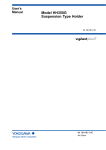
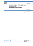
Solution flow rate:
30 to 600 mL/min
Note : The maximum flow rate is restricted by the measured solution conductivity.
Solution conductivity:
Flow Rate of Measured Solution
0.1 μS/cm or more (see following figure)
600
500
400
300
Optimum range
200
100
(mL/min)
F1.0.ai
0
0.1
0.2
0.3
0.4
0.5
0.6
50
Conductivity of Measured Solution (μS/cm)
KCl solution consumption:
Maximum 3 mL/day (10 kPa pressurized)
Weight:
Sensor;
Approx. 0.4 kg (Body)
KCl Tank;
Approx. 0.3 kg (General purpose)
Approx. 0.8 kg (Big volume)
Characteristics :
Output Response:
Response time (for 90% response): 10 seconds maximum
(when the sensor, stabilized at 20°C, measures a solution at 20°C).
IM 12B7J2-01E
10th Edition : Oct.31,2015-00
1-2
< 1. Specification >
1.2
Model and Suffix codes
l pH Sensor
Model
Suffix Code
Option Code
Description
PH8EHP
.............................................. ..................... pH sensor for high purity water
Cable Length
-03
-05
-07
-10
-15
-20
.....................
.....................
.....................
.....................
.....................
.....................
-TN
Solution Ground Tip
..................... Always -N
-H
-E
-F
-G
Measuring System
.....................
.....................
.....................
.....................
For PH200/PH400 (*2)
For PH202/FLXA202/FLXA21 (*3)
For FLXA202/FLXA21 (*5)
For PH450G, PH202/TB (*4)
*A ..................... Style A
Style
*1:
*2:
*3:
*4: *5: ..................... For general purpose (250 mL solution inlet)
..................... Big volume tank (With 500 mL tank)
..................... For maintenance (for TT1)
-N
-
10 m
15 m
20 m
..................... Titanium
-TT1
-TT3
-TN1
KCl Reserve Tank
(*1)
3m
5m
7m
Only a KCl supply tube is supplied with TN1. KCl solution is supplied with TT1 and TT3.
Mark band is shown by alphanumeric and fork terminals are used.
Mark band is shown by numeral and pin terminals are used. When terminal box is used, select WTB10-PH1.
Mark band is shown by numeral and M3 ring terminals are used. When terminal box is used, select WTB10-PH3.
Mark band is shown by numeral and M4 ring terminals are used. When terminal box is used, select WTB10-PH5.
lAccessories
Model
Suffix Code Option Code
Description
PH8AX
.................... ..................... Accessories for pH meter (*1)
Calibration
Reagents
-L
-P
*A
Style
Option
*1:
*2:
..................... Two bottles, each containing 250 mL solution (pH7 and pH4)
..................... 24 bags, each bag containing powder for 500 mL solution (pH7 X
12 bags and pH4 X 12 bags) and two 500 mL polyethylene bottles.
..................... Style A
/STD
/KCLL
/KCLP
/TMP
Sensor stand (with mounting bracket for 50A 2-inch pipe)
KCl solution (one 250 mL polyethylene bottle)
KCl powder (three bags, 250 mL solution each)
Thermometer (0 to 100 °C)
Including the following:
Two 200 mL polyethylene cups
One cleaning bottle
Either /KCLL or /KCLP is required for PH8EFP-□-□-TT2.
IM 12B7J2-01E
10th Edition : Oct.31,2015-00
1-3
< 1. Specification >
lConsumables
Part Name
Part
Number
Remarks
Glass electrode
K9142TN
One
Junction
K9142TK
One
KCl solution (3.3 mol/L)
K9084LP
Six 250 mL polyethylene bottles
Buffer solution for calibration (pH 4)
K9084LL
Six 250 mL polyethylene bottles
Buffer solution for calibration (pH 7)
K9084LM
Six 250 mL polyethylene bottles
Buffer solution for calibration (pH 9)
K9084LN
Six 250 mL polyethylene bottles
Powder for buffer solution (pH 4)
K9020XA
12 bags, each for preparation of 500 mL
Powder for buffer solution (pH 7)
K9020XB
12 bags, each for preparation of 500 mL
Powder for buffer solution (pH 9)
K9020XC
12 bags, each for preparation of 500 mL
KCl powder (for PH8EHP)
K9020XU
8 bags, each for preparation of 250 mL
Note: The pH value of the calibrating buffer solution may vary depending on storage conditions.
Prepare a new solution from powder for accurate instrument calibration
IM 12B7J2-01E
10th Edition : Oct.31,2015-00
< 1. Specification >
1-4
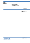
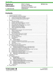
External Dimensions
("-E": Pin terminal) ("-G", "-F": Ring terminal)
("-H": Fork terminal)
GE S RE SE T1 T2
15 16 13 14 11 12
15 16 13 14 11 12
Unit: mm
Cable gland is not included.
Reuse existing gland, or replace.
Cable
length: L
Terminal No. and colors
GE
15 (Red)
RE
13 (Brown)
T1
11 (Black)
T2
12 (White)
SE
14 (Green)
S
16 (Yellow)
Tube
length: L
64
General purpose KCl reserve tank
(with mounting bracket)
(PH8EHP-)-TT1
Ø27.5
Approx.115
115
2-inch pipe
Ø63
Ø38
Big volume tank KCl reserve tank
(with mounting bracket)
(PH8EHP-)-TT3
Approx.75
Approx.45
Approx.105
2-Ø9 (M8 screw) holes
Ø105
Approx.151
2-inch pipe
(Ø60.5)
70±0.2
Hole requirements
for wall mounting
25
1.3
60
60
Figure 1.1
F1.1.ai
PH8EHP pH Sensor
IM 12B7J2-01E
10th Edition : Oct.31,2015-00
2-1
< 2. Installation >
2.Installation
2.1
Preparation for Installation
2.1.1 Unpacking and Inspection
The Model PH8EHP pH sensor is well packed so as to prevent damage during shipment.
After removing the sensor from its shipping container, visually check the sensor for damage.
NOTE
(1)When delivered, the "glass electrode" and the "liquid junction" are packed separate from the
sensor body.
(2)So that caps of the “glass electrode” and the “liquid junction” do not dry out, do not take unpack
these at this time.
MODEL
PH8EHP - 03-TN-TT1-N-H*A
No.
Made in Japan
F2.1.ai
Figure 2.1
An Example of Model Number Entering to Nameplate
Sensor Body
Solution Ground Tip
Glass Electrode
Liquid Junction
Figure 2.2
F2.2.ai
Names of PH8EHP pH Sensor Components
IM 12B7J2-01E
10th Edition : Oct.31,2015-00
2-2
< 2. Installation >
2.1.2 Mounting Glass Electrode
Mount the glass electrode on the sensor body as per the following procedure:
(1) Peel off the seal from the electrode mounting hole on the sensor body.
(2) Remove the cap for the glass membrane. Wipe off any solution remaining on the O-ring with a
tissue or other material.
(3) Remove the cap for the gold-plated pin.
(4) Confirm that there is no damage on the O-ring that might affect its sealing performance.
(5) Mount the glass electrode on the sensor body. Insert the electrode in the mounting hole and
screw it clockwise until the O-ring fits tightly in the hole.
NOTE
• As shown in Figure (a), the cap for the glass membrane contains the solution to keep wet (pH4 buffer
solution). Do not splash the solution when removing the cap. Remove the cap carefully because the
rod beside the glass membrane is very fragile.
• Before mounting the glass electrode on the sensor body, make sure that the O-ring and the goldplated pin are not wet. Wipe off any remaining solution.
• Make sure that there are no droplets in the mounting hole. Wipe off any droplets, or they may cause
insulation failure.
• Use the electrode within one year after purchase. The solution to keep wet gradually evaporates
over time. A glass electrode whose glass membrane has dried out does not provide stable readings
until it gets used to the solution. As shown in Figure (b), place in advance the glass electrode either
in the pH4 or pH7 buffer solution for more than a day before using.
Cap for the gold-plated pin
Make sure the part above the O-ring is not wetted.
Cap for the glass membrane
Solution to keep wet (inside)
Case part No.: K9008WT
(a)(b)
2.1.3 Mounting Liquid Junction
The liquid junction is mounted in the sensor body when the KCl solution is poured into the sensor
body. Refer to Section 2.2.
2.1.4 Installing Holder
Usually, the pH sensor is suspended in a guide pipe or installed in a flow-through or submersible
holder. First install the holder.
2.1.5 Installing Associated Instruments
Make sure that the associated instrument (a pH transmitter/converter or a junction terminal box) to
which the pH sensor cable is connected has already been installed.
IM 12B7J2-01E
10th Edition : Oct.31,2015-00
2.2
< 2. Installation >
2-3
pH Sensor Cable Wiring Procedure
2.2.1 Connecting Sensor Cable
l Connecting Sensor Cable to Terminal Box
(1) Open the cable inlet hole in terminal box using the supplied punch tool. The location of the cable
inlet hole is shown by the circle-shaped groove under the case. The end of the supplied punch
tool is put in the center of this circle and it is tapped with appropriate force. You can punch out the
hole along the groove.
Hole punching tool for wiring
(supplied as accessory)
F2.3.ai
Figure 2.3
How to punch out the wiring hole
(2) Loosen two screws which are at front of terminal box and detach the cover.
(3) After detaching the nut from the cable gland of sensor cable, pull the cable into the terminal box
from sensor cable inlet hole.
After passing the cable through the nut, check the symbol on each core wire, then connect each
core wire to the corresponding terminal.
SENSOR
Connect the sensor cable to the terminals.
CONVERTER
F2.4.ai
Figure 2.4
Connecting Sensor Cable (In case of the PH8TBG)
IM 12B7J2-01E
10th Edition : Oct.31,2015-00
2-4
< 2. Installation >
(4) Mount the cable gland in the cable inlet hole.
Put the nut in place, and screw it onto the main body sufficiently. At this time, loosen the cap so
that the cable is not twisted. After fixing the main body, tighten the cap to keep moisture out of the
equipment. However if the cap is screwed up too tight, the cable will be damaged.
Attach the nut in the
direction shown here
(so that it engages
the detent groove).
Nut
Gasket
Main unit
Cap
Figure 2.5
F2.5.ai
Cable Gland
(5) After completing the cable connections, replace the box cover securely, thus preventing moisture
from getting into the case.
l Connecting Sensor Cable to pH Transmitter/Converter
To connect the sensor cable to the two-wire pH transmitter, proceed as follows:
(1) Loosen the four screws that tighten the transmitter cover. Then remove the transmitter cover.
(2) Connect the sensor cables to the relevant terminals of the transmitter/converter:
First, remove the nut from the cable gland. Insert the cable into the right opening for the wiring.
Then pass the cable through the nut, Connect the individual cable conductors to the relevant
terminals correctly by referring to the markings on the individual conductors.
(3) Install the cable gland in the wiring hole as follows:
Pass the tip of the cable gland into the opening and completely tighten the gland with the nut
inside the case.
After tightening the gland, secure the cap properly to prevent moisture from getting into the case.
Caution: Do not overly tighten the cap. Otherwise, the cable may be damaged.
(4) After completing the cable connections, replace the transmitter/converter cover securely, thus
preventing moisture from getting into the case.
For details, refer to the relevant user's manuals for pH transmitter/converter.
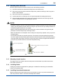
2.2.2 Installing the sensor
(1) Mount the liquid junction in the sensor body. Peel off the seal attached to the liquid junction
mounting hole in the sensor body. Screw the liquid junction gently two or three turns into the
hole.
(2) The PH8EHP pH sensor comes with a KCl solution reserve tank and its mounting hardware
when specified. Attach the mounting hardware to the pipe (nominal diameter 50 mm).
When suffix code "-TT1" is specified, connect the KCl solution refilling tube of the sensor to the
general purpose reserve tank holding a 250 mL KCl solution. With the tube connected to the
sensor, remove the cap from the tank and screw the connector of the tube in securely.
When suffix code "-TT3" is specified, connect the KCl solution refilling tube of the sensor to the
Big-volume reserve tank holding a 500 mL KCl solution.
IM 12B7J2-01E
10th Edition : Oct.31,2015-00
2-5
< 2. Installation >
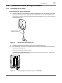
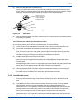
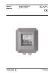
(3) Supply a KCl solution to the sensor.
For the 250-mL KCl reserve tank, mount the reserve tank on the mounting hardware with the
tube connection part facing down. Using a pin supplied with the tank, make several holes in the
upper part of the sides of the tank (see Figure 2.6).
Stand the sensor upside down at a lower position than the reserve tank as shown in Figure 2.6
so that KCl solution flows from the tank into the sensor. When the KCl solution fills the sensor
and overflows from the liquid junction mounting hole, securely screw the liquid junction into the
mounting hole.
CAUTION
How to screw
liquid junction
A
B
When you screw the liquid junction into the mounting hole, grip and rotate the “A” (brown body).
If you grip and rotate the “B” (black body), the liquid junction may be broken.
Leave air space in the tank.
(Make several holes using the
pin supplied with the tank)
Liquid Junction (Loose)
General Purpose
Reserve Tank
Sensor Body
KCl Solution Tube
F2.7.ai
Figure 2.6
Supplying KCl Solution to Sensor Body
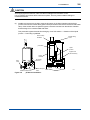
For the 500-mL KCl reserve tank, supply a KCl solution to the reserve tank and close the cover.
Be sure to hold the reserve tank by hand when opening or closing the cover. Also, when further
tightening the fixing nut at the bottom of the reserve tank, be careful not to tighten it too tight.
Excessive tightening may cause cracks in the reserve tank.
Cover
Reserve
Tank
Fixing Nut
KCl Solution
Refilling Tube
To pH Sensor
F2.6.ai
Figure 2.7
500-mL Reserve Tank
IM 12B7J2-01E
10th Edition : Oct.31,2015-00
2-6
< 2. Installation >
CAUTION
After supplying the KCl solution, make sure that no leakage of KCl solutions occurs.
If so, grounding connections will be made at two points. This may cause unstable readings or
measurement errors.
(4) Install the pH sensor to the holder. Insert the pH sensor in the liquid chamber until the liquid
junction in the sensor reaches the bypass in the liquid chamber and secure the sensor with metal
clamp. If the solution does not pass the bypass, remove the sensor from the solution chamber
and submerge it in a container filled with water.
This prevents the glass electrode from being dry out or KCl solution — flowed out of the liquid
junction — from being crystallized.
Sensor clamp
hardware
Bracket fixing
screw
pH sensor
Liquid
junction
Bypass flow
path assembly
Liquid
chamber
Grounding
terminal
Stop
valve
Measured liquid inlet
Figure 2.8
Measured liquid
outlet
F2.8.ai
pH Sensor Installation
IM 12B7J2-01E
10th Edition : Oct.31,2015-00
3-1
< 3. Maintenance on operation >
3.
Maintenance on operation
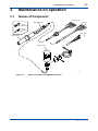
3.1
Names of Component
Tip type (-H)
KCl Supply Tube
Pin type
(-E)
Glass
Electrode
Liquid
Junction
Ring type
(-G)
Sensor Body
Reserve Tank
F3.1.ai
Figure 3.1
Names of Component of PH8EHP pH Sensor
IM 12B7J2-01E
10th Edition : Oct.31,2015-00
3.2
3-2
< 3. Maintenance on operation >
Operation and Periodic Maintenance
3.2.1 Calibrating pH Sensor Using Buffer Solutions
Calibrate pH sensor with buffer solutions before starting normal operation because the emf of glass
electrodes differs somewhat from each other.
The emf of a glass electrode gradually changes due to electrode staining or deterioration.
Therefore, buffer solution calibration must be carried out periodically within a given period of time to
keep the measurement errors within the limits specified.
For more detailed information on the calibration procedures, see relevant pH transmitter/converter IMs.
3.2.2 Replenishment of KCl Solution
When the KCl solution in the tank seems to be nearly exhausted while using a pH sensor with general
type reserve tank, replace the reserve tank with new one (provided separately as spare part).
Instead of tank replacement, when a KCl solution prepared using KCl powder is used for
replenishment, use 3.3 mol/Lsolution by dissolving 246 g of KCl powder in pure water to make exactly
one liter of solution. When pouring the solution into the tank, be careful that KCl solution does not
overflow from the vent holes of the tank.
3.2.3 Cleaning Glass Electrode and Liquid Junction
Staining of a glass electrode or liquid junction can cause measurement errors. Therefore, if its
measured solutions tend to stain the electrode, the glass electrode and liquid junction must be
cleaned periodically — the period depending on the degree of staining.
Submerge the glass electrode in a diluted hydrochlonic acid solution (1 to 2 %) for several minutes.
3.3
Replacing Consumable Parts
3.3.1 Replacing Glass Electrode
If buffer solution calibration becomes impossible due to deterioration of the glass electrode, replace it
with a new one. After the glass electrode is replaced, always carry out a buffer solution calibration.
3.3.2 Replacing Liquid Junction
Even after washing the liquid junction, if normal measurement cannot be made, replace the liquid junction.
When replacing the liquid junction, fill the sensor with KCl solution to just before the solution overflows
through the liquid junction mounting hole. Use a 3.3 mol/l KCl solution (a higher concentration of KCl
or KCl powder) for this application.
1. When the liquid junction
is to be removed.
2. When the liquid junction
is to be installed.
F3.3.ai
Figure 3.2 Replacing Liquid Junction
IM 12B7J2-01E
10th Edition : Oct.31,2015-00
< 3. Maintenance on operation >
3-3
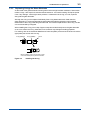
3.3.3 Replacing O-rings for Glass Electrode
As the inside of the glass electrode mounting hole must have high insulation resistance, fluorocarbon
rubber O-rings - with superior chemical and heat resistance - are used for sealing. Except for special
uses. If any damage - which might cause problems - is detected in the O-ring, as a rule, replace it
along with the glass electrode.
Although the O-ring can be replaced individually if the O-ring deteriorates much faster than the
glass electrode, it is recommended that the whole glass electrode be replaced to avoid possible
deterioration of the O-ring inside the glass electrode. For individual replacement of the O-ring, use the
one recommended by Yokogawa.
When installing the O-ring, wind a slip of paper or tape around the thread part on the glass electrode
so as not to scratch the O-ring. Otherwise, such scratches may damage its sealing properties.
For ordering, refer to the Customer Maintenance Parts List (CMPL) at the end of the book to check the
appropriate part number of the O-ring.
O-ring (Ø9/Ø12)
O-ring (Ø6/Ø9)
Screw
Before installing, wind a slip of paper or tape
around the thread part to prevent scratches.
Figure 3.3
Installing the O-ring
IM 12B7J2-01E
10th Edition : Oct.31,2015-00
Blank Page
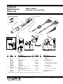
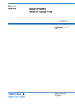
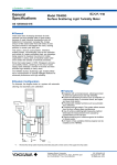
Customer
Maintenance
Parts List
Model PH8EHP
pH Sensor for Purity Water
Name Plate
4
Fork type
3
12
Pin type
2
13
Ring type
1
14
5
8 (9 through 11)
6
11
10
9
9 10
11
9
7
8 (9 through 11)
Item
1
2
3
Part No.
Below
—
Qty
1
4
5
K9142EJ
Below
K9142PF
K9142PG
K9142NH
K9142NJ
K9142NK
K9142NL
(L9901MB)
L9813UG
K9084KQ
1
1
3 or 5
1
6
7
K9084KV
K9084CG
1
1
Description
Body Assembly
see GS 12B07B02(E)
Cap
KCI Filling Tube *
Length 3 m
Length 5 m
Length 7 m
Length 10 m
Length 15 m
Length 20 m
(Length by meter, max.100 m)
Clamp
Bottle for general use (250 mL)
(Suffix Code: -TT1)
Connector Assembly (for general use)
Nut
10
8 (9 through 11)
Item
8
9
10
11
12
13
14
Part No.
K9142VE
—
—
—
Below
K9142TN
Qty
1
3
3
1
K9142QR
K9142QS
1
1
Below
K9142TK
1
K9142QR
1
K9142VS
1
1
Description
Holder Assembly
B.H. Screw, M4 X 18
Nut
Bracket
Glass Electrode Assembly
for general use
O-Ring, 6 mm ID. X 9 mm OD.
O-Ring, 9 mm ID. X 12 mm OD.
Junction Assembly
for pure water use
O-Ring, 6 mm ID. X 9 mm OD.
Tank assembly for use 500 mL
(Suffix Code: -TT3)
* Length of KCl Filling Tube shall be less than 60 m in case of TIIS version (Suffix code: -T, for FLXA21)
All Rights Reserved, Copyright © 1987, Yokogawa Electric Corporation.
Subject to change without notice.
CMPL 12B05J02-01E
8th Edition : Jun. 2015 (YK)
i
Revision Information
: Model PH8EHP pH Sensor for High Purity Water
Title
Manual No. : IM 12B7J2-01E
Aug. 2015/10th Edition Added FLXA202, Unification ot the material name
P i, P1-1, P1-2.
Aug. 2015/9th Edition
Page ii to iii Added a postscript about Compliance with the simple apparatus requirements.
Jun. 2013/8th Edition
P 1-1 Some revision of Sec. 1.1 Standard Specifications; P 2-1 to 2-2 Some revision of Sec. 2.1.1 and
2.1.2 (addition of the cap to keep the glass electrode wet); P 2-5 to 2-6 Addition of caution to screw the
liquid junction; P 3-2 to 3-3 Deletion of Sec. 3.2.1 (how to keep the glass electrode wet moved to Sec.
2.1.2) and following section no. and page layout changed.
Jul. 2011/7th Edition Page layout changed by InDesign
P i, Reference manual number of FLXA21 added.
P 1-2, M4 ring terminals for FLXA21 added to MS-code.
P 1-4, M4 ring terminals added to external dimensions.
CMPL 12B05J02-01E revised to 6th edition (Note for 500 ml KCl tank modified).
Mar. 2010/6th Edition
P3-1 to 3-2, Section 3.2.1 has been changed to "Advance Preparation", and section order change as
following. "3.2.2 Calibrating pH Sensor Using Buffer Solutions", "3.2.3 Replenishment of KCl Solution",
"3.2.4 Cleaning Glass Electrode and Liquid Junction". Some of Section 3.3.1 "Replacing Glass
Electrode" modified;
P3-4, Changing page of Section 3.3.2 "Replacing Liquid Junction."
Apr. 2008/5th Edition
M3 ring terminals added for PH450G, CMPL12B05J02-01E revised to 5th edition.
Oct. 2006/4th Edition
Caution for KCl solution leakage of reserve tank added to 2.2.4 Installing the sensor.
Jul. 2006/3rd Edition
All over revised.
Feb. 1993/2nd Edition
Some error corrected.
Dec. 1983/1st Edition
Newly published.
IM 12B7J2-01E
Blank Page