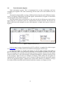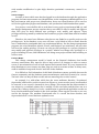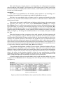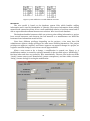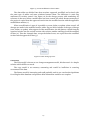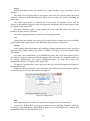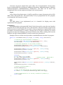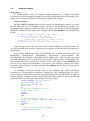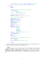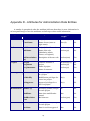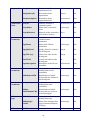
1
School of Innovation, Design and Engineering MASTER THESIS IN COMPUTER SCIENCE 30 HP, ADVANCED LEVEL Principles of a Central Database for System Interfaces during Train Development Author: Peter Lännhult Email: [email protected] Date: 14 April 2011 Carried out at: Bombardier Transportation AB Advisor at Bombardier Transportation AB: Filip Sebek Advisor at MDH: Dag Nyström Examinator: Mats Björkman, Mälardalen University ABSTRACT This thesis has developed a database solution for storage of interface data which are to different systems in a train, the interface data is used in the design of data communication between different systems in the vehicles. The database solution has focused on following problems: revision control of project related data, consistency of interface data between documentation and database, the possibility to roll back the database to an earlier revision, and the possibility to extract delta documents between two revisions in the database. For demonstration of the database solution, a user interface program has been created which communicates with the database. Revision control of the database has been solved by dividing the project related data into three sections: one approved, one modified, and one revised section. The approved section always contains the latest approved data and thereby the ability to read data even though it is subject for a revision at the moment. The modified section contains data that are currently being changed. Obsolete data are stored in the revised section. To aviod inconsistency of interface data which are stored in both Word documents and in the database, the data is extracted from the database and inserted into tables in the Word documents. The Word documents contain bookmarks where the tables shall be inserted. Algorithms for rolling back the database to an earlier revision, and to extract delta documents were created. These algorithms are not implemented in the user interface program. As a result from this thesis, the interface data is revision controlled and no data is removed from the database during the change process; the data is moved between sections with different flags and revision numbers. Only if the database is rolled back to an earlier revision, data is removed. The functionality to transfer data from the database into tables in Word documents is verified. ii SAMMANFATTNING Detta examensarbete har tagit fram en databaslösning för lagring av gränssnittsdata för olika systemenheter i ett tåg, gränssnittsdatat används i konstruktionen av kommunikation mellan olika system i fordonen. Databaslösningen har fokuserats på följande problem: revisionskontroll av projekt relaterat data, att gränssnittsdata överensstämmer mellan dokument och databasen, möjligheten att kunna gå tillbaks till en tidigare revision i databasen, samt möjligheten att kunna exportera delta dokument mellan två revisioner i databasen. För att demonstrera databaslösningen har ett användarprogram skapats som kommunicerar med databasen. Revisionskontroll i databasen har lösts genom att dela upp det projektrelaterade datat i tre sektioner: en godkänd, en modifierad samt en reviderad sektion. I den godkända sektionen finns alltid det senast godkända datat och möjligheten att läsa dessa data även om den är under ändring. I den modifierade sektonen finns data som är under pågående ändring. Data som har blivit ersatt återfinns i den reviderade sektionen. För att undvika inkonsekvens av gränssnittssdata som återfinns både i Word-dokument samt i databasen, extraheras datat från databasen till tabeller i Word-dokumenten. Worddokumenten innehåller bokmärken där tabellerna sätts in. Algoritmer är framtagna för att kunna backa tillbaka till en tidigare revision i databasen samt kunna exportera delta dokument. Dessa algoritmer är inte implementerade i användarprogrammet. Detta examensarbete har resluterat i att gränssnittsdatat är revisionskontrollerat och inget data tas bort från databasen under en ändringsrutin, datat flyttas bara mellan olika sektioner med olika flaggor och revisionsnummer. Endast om man går tillbaks till en tidigare revision tas data bort ur databasen. Funktionaliteten att överföra gränssnittsdata från databasen till tabeller i Word-dokument är verifierad. iii PREFACE This is a thesis at advanced level in Computer Science at School of Innovation, Design and Engineering at Mälardalen University. It was carried out at Bombardier in Västerås. I would like to thank my son Kevin for inspiration in life, and my supervisors at Bombardier and Mälardalen University for their insight in computer science and support of this thesis. There are many other people who have helped me carry out this thesis, thanks to you all. Västerås, April 2011 Peter Lännhult iv ABBREVIATIONS ACID Atomicity, Consistency, Isolation, Durability CCTV Close Circuit TV CCUO Central Computing Unit Operation DB DataBase DBDL Database Design Language DBMS DataBase Management System ER Entity-Relationship FK Foreign Key GDB tool Generic Database Management Software GUI Graphical User Interface HVAC Heating Ventilation and Air Conditioning ICD Interface Control Document IPT Internet Protocol Train ISO International Organization for Standardization MD Message Data MS Microsoft MVB Multi Vehicle Bus ODBC Open DataBase Connectivity PD Process Data PDM Product Data Management PIS Passenger Information System PK Primary Key SQL Structured Query Language TCMS Train Control and Management System TTL Time To Live TIS Train Information Systems VCS Vehicle Control Simulator XML Extensible Markup Language v CONTENTS Chapter 1 1.1 1.2 1.3 1.4 INTRODUCTION 1 Background ..........................................................................................................1 Motivation ............................................................................................................1 Requirements ...................................................................................................... 2 Problem Formulation ......................................................................................... 3 Kind of Database ....................................................................................................................... 3 Change Management ................................................................................................................ 3 ICD Data Consistency ............................................................................................................... 3 User Concurrency ..................................................................................................................... 4 Database Architecture .............................................................................................................. 4 Graphical User Interface .......................................................................................................... 4 Data Security ............................................................................................................................. 4 1.5 Contributions ...................................................................................................... 5 Database Management tool ...................................................................................................... 5 Change management ................................................................................................................ 5 ICD Data Consistency ............................................................................................................... 5 Graphical User Interface .......................................................................................................... 5 1.6 Limitations .......................................................................................................... 5 1.7 Methods .............................................................................................................. 7 Interface Data Process .............................................................................................................. 5 Studies of Work Process ........................................................................................................... 7 Studies of Relevant Change Management Methods ................................................................ 7 Testing the Solution .................................................................................................................. 7 Chapter 2 2.1 RELATED WORK 8 Database Theory ................................................................................................. 8 Introduction .............................................................................................................................. 8 Database Models ....................................................................................................................... 8 Programming ........................................................................................................................... 11 Integrity Constraints............................................................................................................... 12 Transactions ............................................................................................................................ 13 ACID ........................................................................................................................................ 13 Concurrency ............................................................................................................................ 13 2.2 2.3 2.4 Database Management System Survey ......................................................... 14 Train Information System ............................................................................. 16 GDB Tool ....................................................................................................... 18 Data Storage ............................................................................................................................ 18 Graphical User Interface ........................................................................................................20 Change Management .............................................................................................................. 21 User Access ............................................................................................................................. 21 Administration ........................................................................................................................ 21 Chapter 3 3.1 3.2 3.3 DESIGN INVESTIGATION 22 Requirements .................................................................................................... 22 ICD Data Consistency ................................................................................... 22 Change Management..................................................................................... 23 Locking .................................................................................................................................... 23 User Privileges ........................................................................................................................ 24 Finance Model ........................................................................................................................ 24 Copy Model ............................................................................................................................. 25 vi Wire Model.............................................................................................................................. 26 Conclusion............................................................................................................................... 27 Chapter 4 4.1 SYSTEM DESIGN 28 Database Architecture....................................................................................... 28 Conceptual Design ..................................................................................................................28 Logical Design ......................................................................................................................... 32 4.2 4.3 Chapter 5 5.1 Change Management..................................................................................... 37 ICD Data Consistency ................................................................................... 42 RESULT 43 Graphical User Interface Program.................................................................... 43 Menu and Status Field ............................................................................................................ 43 Programming .......................................................................................................................... 45 5.2 Database Schema .......................................................................................... 46 Programming .......................................................................................................................... 46 Chapter 6 6.1 6.2 6.3 6.4 6.5 Chapter 7 CONCLUSION AND DISCUSSION 48 Change Management ........................................................................................ 48 ICD Data Consistency ................................................................................... 48 User Concurrency .......................................................................................... 49 Graphical User Interface ............................................................................... 49 Data Security ................................................................................................. 49 FUTURE WORK 50 7.1 Database............................................................................................................ 50 7.2 User Interface Program .................................................................................... 50 Data security ........................................................................................................................... 50 Login ........................................................................................................................................ 50 Copy and Delete Project ......................................................................................................... 50 Export ...................................................................................................................................... 50 Help ......................................................................................................................................... 51 User Manual ............................................................................................................................ 51 7.3 7.4 Work Process regarding ICD Data .....................................................................51 Testing................................................................................................................51 Delta document ....................................................................................................................... 51 Copy a project ......................................................................................................................... 51 Delete a project ....................................................................................................................... 51 Chapter 8 REFERENCES 52 Appendix A - Requirements 54 Appendix B - XML File 57 Appendix C - Header File 59 Appendix D - Attributes for Administration Data Entities 64 Appendix E – Attributes for DB Data Entities 65 vii Appendix F – ER Diagrams 71 Appendix G – Relations 73 FIGURES Figure 1. Interface data process .......................................................................................... 6 Figure 2. Hierarchical model .............................................................................................. 9 Figure 3. Database table Employee .................................................................................... 9 Figure 4. Database table Salary ........................................................................................ 10 Figure 5. Simple ER diagram............................................................................................ 10 Figure 6. Object oriented model [30] ................................................................................ 11 Figure 7. Simple train layout [3]........................................................................................16 Figure 8. Dataset example [4] ........................................................................................... 17 Figure 9. Current interface data process ...........................................................................19 Figure 10. Table CarType .................................................................................................. 20 Figure 11. GDB tool ........................................................................................................... 20 Figure 12. Table Car .......................................................................................................... 24 Figure 13. Table Revision.................................................................................................. 25 Figure 14. Data tables for Car with different revisions ..................................................... 26 Figure 15. Create modification form in Wire .................................................................... 27 Figure 16. Wire change process ........................................................................................ 27 Figure 17. Example of ICD data [1] ................................................................................... 36 Figure 18. Table Car in all 3 sections ................................................................................ 38 Figure 19. Graphical user interface................................................................................... 43 Figure 20. Change menu .................................................................................................. 44 TABLES Table 1. DBMS comparison ............................................................................................... 15 Table 2. Entities for DB administration ........................................................................... 28 Table 3. Entities for DB project data ................................................................................ 30 viii Chapter 1 INTRODUCTION 1.1 Background Bombardier Transportation is a rail equipment manufacturer with operations in 35 countries and has 33,800 employees. The operations include Rail vehicles, Propulsion and Controls, Bogies, Services, Transportation systems, and Rail control solutions. Bombardier is divided in several divisions, and the one that design intercity trains in Västerås is Passenger. The Passenger division is divided in several departments. The department Software, Design and Implementation is responsible for developing Train Information Systems (TIS) which includes Train Control and Management (TCMS), Passenger Information System (PIS), and Closed Circuit TV (CCTV). TCMS have a central role to control and monitor a modern train and have a lot of interfaces to different systems that are distributed in the train, such as doors, pantograph, HVAC (Heating Ventilation and Air Conditioning) among others. Some of these systems are specified and bought from external subcontractors and others are designed by Bombardier. The interfaces to the systems are different kind of serial buses, or the interface is discreet and communications is via digital or analogue inputs and outputs. For testing the system designs, different kinds of test equipment are used. The interfaces to those test equipment‟s needs to be configured for the systems interfaces which are unique for every project. In the vehicles, several kinds of buses are used: Multi Vehicle Bus (MVB), Internet Protocol Train bus (IPT), and the serial buses RS 232, RS 422, and RS 485. A big challenge in ongoing projects is to handle necessary updates of the different interfaces without that error and inconsistencies arise. 1.2 Motivation The goal is to evaluate and establish a central storage place for all data that is needed in the development process of the TIS systems‟ interfaces; this data is named interface data in this thesis. The interface data is all data regarding bus communication between units and I/O operations from the units in the train. For communication on a bus, telegrams are used for transferring data between units; the telegrams are either sent on regular basis, process data (PD), or sent on events, message data (MD). All information regarding telegrams shall be stored in the storage place, both the data structure that is packed in the telegram and telegram attributes such as address, Time To Live (TTL), telegram length, and type of telegram among others. All variables are defined 1 although many values are set at run-time. An example is when a passenger display in the train communicates to the train computer system that the temperature has exceeded its maximum temperature value at the display, then the variable FtemperatureExd is set to the value fault at run-time; otherwise the value will be ok. The storage place for interface data will contain the variables and when applicable, constraints the values to the possible ones, in this case the values fault and ok. Bombardier has developed a database (DB) tool to store a part of TIS interface data, named Generic Database Management Software (GDB tool). It was created at Bombardier‟s site in Crespin (France) and is based on Microsoft (MS) Access. GDB tool is both a database and a user interface application for dealing with the data in the database. Every project has its own database contained in an mdb-file (MS Access), the file is stored by the versioncontrol program Visual SourceSafe; this guarantees version control and a possibility to roll back to an earlier version of the project. But there is no possibility to check which changes that have been made between two versions. Also, only one user at a time can access a certain project unless a user has copied the mdb-file and there are two or more users working in parallel; this causes inconsistency and shall be avoided. The software engineers complain of GDB tool‟s usability, that it is difficult to understand in which order the interface data shall be inserted; the tool only has support for some of the buses that are used in a train. It also lacks some functionality such as multiple access to a project, the ability to check which changes has been made, an approval process when a user updates data. Unfortunately, the developer of GDB tool has quit his employment at Bombardier and the knowledge of the tool is limited. So a better solution is demanded to gain a better controlled environment for storage of interface data; and the storage place shall contain all interface data, not just a part of it. The interface data that is stored in GDB tool is the same data that is stored in Interface Control Documents (ICD); there is one ICD for every subsystem. For example, the subsystem Displays has an ICD which contains information of functionality and communication for the Display system. These documents are written by the software engineers and are intended for subcontractors and for internal use. The interface data are written in predefined tables in the document and transferred to the database, GDB tool, manually. When the database needs to be updated due to project changes, the ICD documents must be changed accordingly. In other words, a change is implemented in both GDB tool and in the ICD documents; the probability for inconsistencies is high and shall be avoided. The interface data will be used by system engineers for effectively create deliverables and design software. The central storage place needs to keep information so exports of data into ICD documents, discreet I/O lists, train configurations files (XML and header files), test equipment files, and information for electrical drawings. 1.3 Requirements Bombardier had some requirements for the new storage solution which the old solution (GDB tool) could not fulfill. This thesis has looked into the possibility to expand GDB tool or use another solution to fulfill the requirements and to have a platform for further functionalities if desired in the future. The storage solution must ensure correctness and consistency of the data at all times. This to avoid things such as, one user is blocking all other users when he/she has checked out the database file from Visual SourceSafe, or that the ICD documents and the stored interface data always are consistent with each other. 2 It shall be possible to see what changes have been made between two revisions, who has approved it and why the changes have been made. In other words, a proper approval process is required where a user initiates changes, and another user checks them and thereafter approves the changes if applicable; during this process, blocking other users for reading data is not allowed or that data is updated before an approval is implemented. The functionality to roll back to an earlier revision shall be remained in the new storage solution, because unwanted changes or inconsistency may occur in a project. The graphical user interface (GUI) shall be more easy to use than GDB tool is today, the users need a more intuitive interface which clarify the insertion order of data. Simultaneous and multiple access of the stored data is required as more than one user works in the same project, and delays are avoided if several users have access to the same data at the same time. To prevent inconsistency, several users can update data in the same project but they are not allowed to update the same data concurrently. 1.4 Problem Formulation To store and manipulate data, some kind of database is the most common solution; it is possible to store the data on regular files at a server, but much functionality that are provided with a database solution will be lost or difficult to implement. This thesis looks into a database solution for storing the interface data. The main problems that this thesis focuses on are listed below; the problems are numbered for easy reference in this report. Kind of Database There are different kinds of databases, depending on how the data is modeled and linked with each other. We need to establish which kind of database model that is best suited to solve our particular problem; if GDB tool is one of these tools that use the chosen database model, then it will be a candidate for the new database solution. P1 – What kind of database model shall the storage of interface data be based on? Is GDB tool based on the chosen database model? If so, can it be expanded to fulfill the requirements or shall a complete new solution be realized? Change Management The work process of handling interface data lacks proper change management today because there is no approval process when a user does a change, which means that no one is checking if the changes are correct. And there is no possibility to retrieve delta information between two revisions in the database, in other words to check what changes that have been made. P2 – How shall the design of change management (revision control) be carried out? Are there any good examples that can be realized? How can delta (difference) information be retrieved from the database regarding changes between two revisions? ICD Data Consistency In the current solution, the software engineers create project specific ICD documents in MS Word which contains interface data regarding bus information. This information is written before it is inserted manually into GDB tool, which can lead to inconsistency if there is some mistyped information in either source; or if either of ICD document or GDB tool is updated but not the other. 3 P3 – How can inconsistency be avoided between data in the ICD documents and those stored in the database? User Concurrency One requirement is that several users can login to the same project concurrently, this because several users‟ works in the same project and need to check or update data at the same time. With this requirement, we need to ensure that inconsistency is prevented if several users try to update the same data. P4 – How can multiple logins to the same project be realized? And how can users be allowed to read the same interface data concurrently without blocking each other or avoid that inconsistency arise? How can several users update the interface data in the same project without interfering each other? How shall the solution prevent that users tries to revise the same data between two approved revisions in the database? Database Architecture A database system must be designed for a deeper understanding of the problem and to ensure that all information are included in the solution and then in the implementation; this to gain a sustainable solution. A good design also makes the solution transparent for others to understand the construction of the database. P5 - How shall the design of the database system be carried out such that problems P2, P3, and P4 are fulfilled as well as Bombardiers requirements? What kind of data shall the database contain and how shall it be related to each other? Graphical User Interface The database solution needs a user interface program to communicate with the database; this because an ordinary user do not have database knowledge. And in order to be intuitive and user friendly, the user interface program will have some kind of graphic interface with a logical order of buttons, drop-down menus, and presented information. P6 – How will a GUI look like to achieve the users‟ acceptance regarding intuitive handling of interface data? How shall input of interface data be carried out? What kind of documents needs to be exported and how shall it be realized? Data Security The interface data is very important in a project as it contains the key information between different systems in a train; this data needs to be protected from distortion and unauthorized manipulations. If the data for some reason have errors, rolling back to an earlier version is a requirement from Bombardier. P7 – How can unauthorized access to the database and the user interface program be avoided? What kind of user privileges shall the new storage solution have? How shall the design for rolling back the interface data to an old revision be implemented? 4 1.5 Contributions This thesis has answered the questions addressed in the problem formulations defined in chapter 1.4. There are problems such that disc failure issues, or proper login handling among others, that this thesis has not answered due to lack of time. The chosen database supports a good solution of these problems and they are mentioned in chapter 7.1 as a recommendation for implementation in the future. The contributions from this thesis are numbered for easy reference in this report. Database Management tool C1 – A database management tool has been evaluated and chosen with respect to the problems P1, P2, P4, P5, and P7. Change management C2 - Three different kinds of change management solutions were evaluated where a well-proven one was chosen and adapted to suit our database. The change management solution solves the user concurrency problem and handles user privileges; it also gives a foundation for rolling back the database if necessary. This contribution is related to the problems P2, P4 and part of P7. ICD Data Consistency C3 – A process for handling ICD data has been proposed where the database is the main source for ICD data. This guarantees that the interface data always are accurate and updated in a controlled environment. This contribution is related to problem P3. Graphical User Interface C4 - A graphical user interface program has been created to communicate with the database. This is related to problem P6. 1.6 Limitations This thesis has considered the whole process with a solution for storage of interface data, but only implements a part of the solution due to lack of time. The implementation covers graphical user interface program and database management, with respect to the IPT bus. The other bus types are considered in the architecture of the database management solution but not implemented. The discreet analogue and digital I/O signals are not considered in the design solution but as they are independent of the bus data, it is quite easy to implement them in the same database solution. Interface Data Process The process of the interface data from input to the database, then output to various kinds of documents is shown in Figure 1. Interface data process. The green boxes represent the database solution in this thesis. 5 Figure 1. Interface data process 6 1.7 Methods This thesis spans from understanding current work process regarding handling of interface data as well as document storage, implement user interface, database management, and testing that the solution works as intended. For this several methods have been used as interviews, reading literature, and using software tools. Studies of Work Process Every software tool is linked to a working process and either needs to adapt to the other. In order to understand the current work process regarding handling of interface data, interviews with several employees, both managers and design engineers, have been carried out. The objective was to improve the process as well as the data handling. Internal Bombardier documents and various kinds of interface data files were collected, see documents [1], [3], [4], [5], and [6]. The current database GDB tool was studied in order to understand what kind of data and in which format the new database solution must handle, this study were primarily for assurance that all interface data regarding IPT bus was taken into consideration in the new solution. The ICD work process was investigated by interviews with Product Data Management (PDM) responsible within Bombardier, mainly Martin Svartz. Studies of Relevant Change Management Methods Choosing a method for change management is one of the main problems in this thesis, the information of how to revision control the data in the database is not well documented on internet. The main sources for the solution presented in chapter 4.2 are interviews with Attila Flamborg, experienced with Oracle databases; and Dag Nyström, experienced with Mimer databases. Testing the Solution To test the new database solution, a graphical user interface program has been developed to interact with the database and thereby confirm the proposed solution. Various functions, such as revision control, metadata about projects, and that user data are consistent and correct were tested by running a test project; the test project have several fictive users with different user rights and several modifications were open at the same time for testing that reading and writing to the database works as intended. 7 Chapter 2 RELATED WORK This chapter describes related work and related areas; also a description of the previous database tool, GDB tool, which is used within Bombardier, is given. 2.1 Database Theory Some basic database theory is described for easier understanding of this thesis intended for readers not familiar with databases and their functionality. For further knowledge in this area, see [2] (Swedish), [24] or other literature in this field. Introduction A database is a collection of data that describes or models something, in our case the database models the system interfaces for TIS data. A database management system (DBMS) is a program that organize, store, manage, and retrieve data in a database. Examples of DBMS programs are Oracle, MySQL, DB2, Microsoft (MS) SQL Server and Postgre SQL. MS Access is sometimes mentioned in this context but it is rather an application program using JET as DBMS; in this thesis MS Access will be considered as a DBMS with the implicitly that JET is running in the background. A database and DBMS is often mistaken for each other but the database is the collection of data and DBMS is a program handling the data in the database. Database Models A database is often quite complex with different kind of data which is related to each other; in order to organize these data, a database model is used. There are several database models which the most common ones are Hierarchical, Network, Relational, and Objectoriented models. Hierarchical Model A hierarchical model is a tree-structure model with parent/child relationships between data objects. A parent object can have multiple children but a child can only have one parent [27], see Figure 2. This model is good for simple one-to-many (1:N) relationships but does not perform very well when dealing with more complex many-to-many (N:M) relationships. Hierarchical databases were popular from late 60‟s through 70‟s, but have become more or less obsolete when the relational model was developed. 8 Figure 2. Hierarchical model Network Model The network model was invented by Charles Bachman [28] and was first published 1969. This model uses records and sets to represent data objects (records) and its relations (sets). This model is similar to the hierarchical model but allows a record to have N:M relationships. See web site [29] for further details. Relational Model The relational model was invented by Edgar Codd [31] in 1970, when he issued the paper “A Relational Model of Data for Large Shared Data Banks”. In a relational model, which is the most common model used today, the data are organized in tables. A database contains entities (objects) and its attributes, and relationships between the entities. The columns in the tables are the data attributes, and the rows (also named tuples) contain the actual data. The tables are the entities of the database and the associations between tables are the relationship. Figure 3 shows an example of a database table (entity) named Employee with the attributes Employee nr, Name, and Telephone nr. Employee Employee nr 100 101 102 Name Oscar Anna Per Telephone nr 1245 1250 1251 Figure 3. Database table Employee To identify specific rows, keys are used; several attributes can be combined to act as a key. In this example, we can use Employee nr and/or Telephone nr as keys provided that they are unique for each employee. The attribute Name is a bad choice of key because of the possibility that several employees have the same name is quite high. There are several kinds of keys: primary, candidate, foreign, super and alternate keys. Here we only explain the primary key (PK) and foreign keys (FK), for further details about keys, see [2] or [24]. A primary key is a unique key to identify each row in a table and there is only one primary key for each table (could be combined from several attributes). In table Employee, Employee nr is a primary key which is denoted by the underline in the table. A foreign key is a reference key to another table, in this thesis it always refers to a primary key. For example if 9 we have a table Salary that lists how much each employee earns every month, the foreign key will be Employee nr which refers to Employee nr in table Employee. See Figure 4. Salary Salary Id 1 2 3 Employee nr 100 101 102 Salary 15000 15500 17000 Figure 4. Database table Salary It is possible to skip a value in some attributes (not keys), it will be denoted NULL which means they are empty (not zero). The DBMS can set up Views of the database so different users/application programs only see a part of the database, this is useful to prevent access to certain parts and this functionality makes it possible to customize the appearance of data. A database schema is a description of the database structure containing tables, attributes, relationships between tables, and indexes; in other words metadata of the database. For further details, see [26]. In the conceptual stage of designing a relational database, Entity-Relationship (ER) diagrams is used. ER diagrams are used to draw entities with its attributes and relations to other entities. Figure 5 shows an example of an ER diagram, the relationship shows that one employee belongs to one department but a department can have several employees. Employee has the primary key Employee_nr and the foreign key Department nr, the latter indicates a relation to table Department. Figure 5 is drawn in Crow‟s notation. Employee and Department are called entities and will later in the design process end up as tables. Figure 5. Simple ER diagram Object-Oriented Model An object-oriented model has objects, classes, and inheritance very similar to an objectoriented programming language. Usually the same type system is used both in the DBMS and in the application program for easier programming. Figure 6 shows an example with two objects and an instance of an object [30]. 10 Figure 6. Object oriented model [30] Programming In order to create, update, and remove tables in a database, the Structured Query Language (SQL) is the most common one to use. It is a standard language for accessing relational and object-oriented databases, all major DBMS‟s support SQL. It is possible to integrate SQL in application code written in, for example, C++ or C#. Unfortunately, the DBMS‟s have their own variants of SQL which differ slightly from each other; this complicates the design and coding. Therefore, Microsoft has developed the language Open DataBase Connectivity (ODBC) for a better standard communication between the application code and the DBMS. See web sites [20] and [21] for further details about ODBC. An example of SQL code is: SELECT * FROM Employee WHERE Name = “Kalle”; This query asks for all data that has the name Kalle in the table Employee. To achieve better control over a database, it can have active rules called triggers; see web sites [22] and [23] for further details. It is procedural code that executes when certain events happens on a tables(s), view(s) or database. These events are insert, delete, and update of a table; triggers can be used for logging data, prevent unauthorized deleting of data, or enforce certain business rules. Most of the DBMS‟s today support stored procedures, which are code stored on the database server and can be called from an application program, another procedure, or a trigger. The procedure returns row values from a table and can have parameters as input. If we want a single return value, functions can be used. For describing relations, Database Design Language (DBDL) notation can be used, the format is: Employee (EmployeeNr, Name, TelephoneNr, DepartmentId) Primary Key EmployeeNr Foreign Key DepartmentId references Department (DepartmentId) This means that table Employee has the attributes EmployeeNr, Name, TelephoneNr, and DepartmentId, where DepartmentId is a foreign key related to table Department. 11 Integrity Constraints In a database, integrity constraints are needed to avoid errors as much as possible. DBMSs have slightly different integrity rules but most of them apply to the described rules below. Here, we describe five integrity rules as denoted in chapter 7.2 in [24]: required data, domain constraints, entity integrity, referential integrity, and general constraints. The rules are for relational DBs primarily but similar rules can be applied for other kinds of databases. Required Data Some data are required in a database; for example if we have an employee, he must have employee number. This requirement is called required data. The SQL ISO (International Organization for Standardization) standard states that the SQL commands CREATE and ALTER TABLE can be specified as NOT NULL, according to chapter 7.2.1 in [24]. This means that we can enforce data to not have NULL values. Example: Name VARCHAR (20) NOT NULL This means that attribute Name is not allowed to be empty, it must have a name. Domain Constraints Data have a legal set of values, so called domain constraints. For example, may employee number have minimum value 100000 and maximum value 999999, or user name may have the constraints of only allow letters. According to SQL ISO standard, domain constraints can be set in the CREATE and ALTER TABLE statements with the CHECK and CREATE DOMAIN constraints, see chapter 7.2.2 in [24]. Example with CHECK constraint: Employee_number INT NOT NULL CHECK (Employee_number >= 100000 AND Employee_number <= 999999)) Entity Integrity A primary key must have a unique and NOT NULL value for each data row (in a table). The PRIMARY KEY constraint can be used with the CREATE and ALTER TABLE statements according to SQL ISO standard. See chapter 7.2.3 in [24] for further details. Referential Integrity Referential integrity [8] means that all references in the database must be valid. If table Salary have a reference of name Kalle from table Employee, then Kalle must exist. Foreign keys must always have referential integrity, in other words refer to a valid primary key; if the primary key is deleted, the DBMS shall either delete the foreign key as well or refuse to delete the primary keys. According to SQL ISO standard, referential integrity can be set in the CREATE and ALTER TABLE statements with the FOREIGN KEY constraint, see chapter 7.2.4 in [24]. Example: FOREIGN KEY (Employee_Id) REFERENCES Employee (Employee _Id) This means that attribute Employee_Id in table Salary refers to attribute Employee_Id in table Employee. 12 General Constraints A general constraint is similar to domain constraints but is applicable to more than one table. The SQL ISO standard has the CREATE ASSERTION statement for allowing general constraints to be used by several tables. See chapter 7.2.5 in [24] for further details. This feature is not available in all DMBSs. Transactions According to [24], “A transaction is a logical unit of work consisting of one or more SQL statements that is guaranteed to be atomic with respect to recovery”. This means that a unit of commands (transaction) is indivisible regarding execution of them; other concurrent executing commands are not able to interrupt. A transaction either COMMIT or ROLLBACK, in other words it either completes the execution successfully or aborts the execution and undo eventual changes in the database. ACID For reliable database transactions: Atomicity, Consistency, Isolation, and Durability (ACID) properties are recommended. Atomicity An indivisible transaction with the property that either shall all commands in the transaction be executed or none. Consistency Quote from [24], chapter 22.1.1: “A transaction must transform the database from one consistent state to another consistent state”. This rule can only be implied for constraints that have been specified in the database schema. Isolation In concurrent transactions, a transaction must be executed independently of other transactions. Durability All committed transactions shall be in the database permanently and must survive a system failure; this is usually done by keeping transaction logs. Concurrency When multiple users access a database concurrently, locking is needed to prevent them from writing to the same data and have inconsistency as a result. There are two main concurrency control mechanisms in a database: pessimistic and optimistic. A pessimistic concurrency control locks the records immediately while in optimistic the locking occurs during update of the records. It is recommended to use pessimistic when the risk for conflict is high and optimistic if the system have relative few users and the updates are not likely to occur at the same time. 13 2.2 Database Management System Survey In order to choose a Database Management System (DBMS), we must first evaluate if the database shall be relational or object-oriented. An object-oriented database works with objects just like an object-oriented programming language, so the database management and the application program becomes the same environment; a relational database on the other hand have two environments, the application program and the DBMS. An object-oriented DB is good when dealing with objects such as multimedia or other complex data types [32]. A relational DB is more standardized (SQL) and quite easy to understand with its tables and relations. Also, the literature of relational DB‟s is extensive comparing to object-oriented DB‟s. This thesis will use a relational DB solution because it is easy to find literature in this field and because the current DB (GDB tool) is a relational DB and we can benefit from the work that is already done. This is related to problem P1 and contribution C1. GDB tool is based on MS Access 2003 which is part of the MS Office package that is installed on Bombardier‟s current computer network, an eventual expansion of GDB tool should therefore still be based on MS Access 2003. At Bombardiers site in Västerås this tool has only been used in two projects, so the user experience is quite low and acceptance for a new tool is high. A new or modified DBMS tool (GDB tool) will be needed to achieve the requirements and expectations in this thesis. We will use standard implementation in order to be as independent as possible of a certain DBMS tool, but every tool has its own way of doing things so the solution will not be totally independent. A DBMS tool shall be able to handle several requirements; in this thesis following requirements shall be considered: MR-13, MR14, MR-23, MR-24, and MR-25. See appendix A for further details. For comparison, following DBMS‟s have been chosen with the criteria of free development software: MS SQL Server 2008 R2, Mimer SQL Enterprise, MySQL 5.1, and MS Access 2003. MS Access 2003 is chosen because GDB tool is based on it, it will then be possible to check if GDB tool could be modified to fulfill the requirements. Table 1 shows a comparison between the DBMS‟s. 14 Comparison MS Access 2003 MS SQL Server 2008 R2 MySQL 5.1 Mimer SQL Enterprise Row-level locking (MR-13) Yes [12] Yes [13] Yes (InnoDB engine) [11] Optimistic concurrency control (no locking) Simultaneous and multiple access to the database (MR13) Yes[12] Yes [13] Yes Yes [15] Referential integrity (MR-14) Partially [8] Yes [8] Yes [8] [9] Yes [15] ACID transactions (MR-24) No [12] Yes [7] Yes [9] Yes [15] Password protection/Access privileges (MR-23, MR-25) Yes [12] Yes [14] Yes[10] Yes [15] Support database triggers No [12] Yes [13] Yes [10] Yes [15] Free software Free software for students Free software for students Free software Free software for developers Table 1. DBMS comparison As MS SQL Server has excellent developer community, fulfills all requirements, and Bombardier‟s network is based on Microsoft‟s products and they have expertise available to continue with this solution it is chosen as the tool to work with in this thesis. This thesis could have been done with MySQL 5.1 or Mimer SQL Enterprise, with slightly different solutions. MS Access 2003 would require more workarounds and is not suitable for this thesis. 15 2.3 Train Information System Train information system, TIS, is investigated due to data terminology and how everything fits together. The same terminology will be used in the new solution as far as possible. The interface data handles a variety of different kind of signals and in different formats, such as IP signals, MVB signals, Serial link signals, and discreet I/O signals. In this thesis only IP interface data will be considered. The TIS systems have several devices in the train; the devices belong to a certain device type which has a connection point for communication between devices. The devices are linked with buses and messages are sent with telegrams. A simple train layout is shown in Figure 7. Figure 7. Simple train layout [3] A device type is a type of system such as CCTV or HVAC; a complete list of device types is in appendix C in [1]. There can be several devices belonging to a device type. A telegram consists of a header and dataset. It can be either message data (MD) or process data (PD); MD‟s are event driven messages and can handle dynamic size data, and PD‟s are messages sent cyclically with static data size [5]. A dataset consist of several signals which are either set or not in the messages, all signals belonging to a dataset are always sent in the messages; Figure 8 shows an example of a dataset. These tables with all signals are standardized for each system and a cross in column X indicates that this particular project will use the appointed signals. A dataset may contain other datasets, see chapter 4.2 in [5]. For further details about MD and PD headers and their contents, see chapter 5 in [6]. 16 DISCtrlOp2 X Req level Data name Description X CEndMessage End of message B Type Value Interpretation UINT8 This byte determines the last block of sub messages. Only used in case of multi-block messages. Byte Offset 0 = not end of message 1= end message 0 of F10 X B CSubMessage Nb Sub message number UINT8 This defines the block message ordering X B 5-7 reserved B CMessageLen gth Number of CHART CMessage Message 1 1 to 4 = block message F11 X 0 = single message = UINT16 2-3 F12 CHART String message (character and 8 [1000] bitmap format) 0..1000 41003 This message shall be UTF8 encoded F13 Reserved UINT8[ 18] Figure 8. Dataset example [4] A connection point connects two or more devices to each other with the correspondent dataset and a direction, named source or sink. A bus connects devices, either directly or via switches, there are several buses on a train and the communication between them is via units named CCUO (Central Computing Unit Operation). The train have several cars and a complete unit of cars are called consist. According to requirement MR-34, different configurations shall be supported by the database, for example 7 or 8 car-trains which correspond to different consists configurations. Bus architecture contains of devices, types of buses, applied cars/consists. In the current solution, the input of data into the database must be in a certain order because of dependencies, see chapter 5 in [3] for further details. Although we will have a different solution and probably another kind of database management, it is likely that the dependencies will be similar. It is therefore interesting to know the current insertion order. 17 1004 1023 In GDB tool the inputs are divided in three main areas: ICD Global, Architecture, and ICD Specific. The insertions follow the steps below. 1. ICD Global a. Device Type b. Dataset c. Connection Point 2. Architecture a. Bus b. Device c. Car Type d. Consist Type e. Bus Architecture 3. ICD Specific a. MVB or IP Attributes (parameters related to communication) The new solution must be able to export xml and header files of the IP interface data. There is one xml file per system; a truncated example is in appendix B (telegrams and datasets are removed for space reasons). There is one header file per system and one per telegram; an example is in appendix C. 2.4 GDB Tool Generic Database Management Software (GDB tool) is a relational database with user interface application and is developed by Bombardier at Crespin (France); the developer has quit his employment at Bombardier so a deep understanding of the tool within the company is lost. The objective with the tool is to handle all interface data regarding bus communication. It is based on MS Access 2003 which is part of the MS Office package that is installed at Bombardier‟s computer network. Data Storage According to [1], MVB and IPT bus protocols are supported by GDB tool even though only IPT bus based systems have been stored in the database in Västerås. GDB tool is missing support of the serial buses RS 232, RS 422, and RS 485. GDB tool is not able to export discreet I/O lists, serial interface configurations, and MVB signal lists; the latter at least at Bombardier‟s site in Västerås. Figure 9 shows the current process, from GDT tool point of view, of input and exports from GDB tool in Västerås; it also shows the database Vehicle Control Simulator (VCS) which is used in testing the design. Other Bombardier sites might have a slightly different process. 18 Figure 9. Current interface data process The database stores data about system types, devices (instances of systems), buses, cars, consists (train configurations), telegram attributes, datasets (data contained in telegrams), among others. They are stored in tables with attributes and relations between the tables. For example is table CarType which has the attributes CarTypeId, CarTypeName, and MaskIndex; see Figure 10. CarTypeId is a unique identification of the car, CarTypeName is the name of the car, and MaskIndex is a mask to distinguish every car when communicating with it; the same car can occur several times in a train set, so mask index makes them unique. 19 Figure 10. Table CarType Graphical User Interface In GDB tool the data inputs are divided in three main areas: ICD Global, Architecture, and ICD Specific. According to [3], the insertions follow the steps below. 4. ICD Global a. Device Type b. Dataset c. Connection Point 5. Architecture a. Bus b. Device c. Car Type d. Consist Type e. Bus Architecture 6. ICD Specific a. MVB or IP Attributes (parameters related to communication) The interface data has a lot of dependencies, for example a connection point cannot be inserted without dataset, and a dataset cannot be inserted without a device type. The terminology is confusing as ICD is a name of a document type rather than database related, even though the same interface data is stored in both ICD documents and in GDB tool. Figure 11 shows the interface menu for GDB tool with ICD Global, Architecture, and ICD Specific as drop-down menus. Figure 11. GDB tool 20 In the user manual for the tool [3], there are explanations of how to use it. Unfortunately, the insertion order of interface data is not described in correct order. For example, the manual starts with insertion of connection points even though device types and datasets must be inserted first. This, together with confusing terminology such as ICD Global and ICD Specific, confuses the users of the tool. Change Management There is no possibility to check which changes have been made in the tool, so called revision control even though the database files are stored in Visual SourceSafe. This only guarantees version control and possibility of roll back but no possibility to get knowledge of what happened between two versions. Also, there is no possibility to get a delta document (difference) to see which changes has been implemented or comments of the reason for the change. User Access Multiple and simultaneous access to the current database is not allowed, only one user at a time can access the database; this is a big problem as the purpose of the database is to let several software engineers handle the same data. This problem will be worse when more interface data are put in the database, either GDB tool will be expanded to handle more bus protocols and other kind of interface data or a new database solution is needed. Administration Users will be applied roles in the tool, and each role is associated to privileges. For example, the role Developer gets privileges to do project related changes in the database. GDB tool will only give access to areas in which the user has privileges. See chapter 7.2 in [3] for further details. It is also possible to set which actions/privileges that each specific role shall have. For example, decide that role Developer can access the actions Delete Data or Backup Database. This is described in chapter 7.1 [3]. 21 Chapter 3 DESIGN INVESTIGATION To understand the complexity of the problems and how to solve them, some investigation is needed. First of all, we need to know exactly what requirements there are on the new solution in order to do the rest of the investigation properly. Change management is a key issue for this thesis and several revision control methods are investigated. How to solve the potential inconsistency between ICD documents and the database is also investigated. 3.1 Requirements In agreement with Bombardier, the requirements in appendix A shall be fulfilled; this lists the main requirements (MR) for the database to be an acceptable solution. In this thesis only requirements with priority 1 must be implemented. Requirements with lower priorities shall be considered in the design if applicable, but not necessarily implemented in this stage. The priority 1 requirements are ICD data consistency, revision control, simultaneous and multiple access, and database management integrity constraints. 3.2 ICD Data Consistency ICD documents have templates for each system, even though they have not been used in Bombardier Västerås. These templates are supposed to be used in conjunction with GDB tool, so interface data is mapped onto these templates. These templates are not stored in Bombardier‟s PDM system, neither are most of the ICD documents. Word documents is usually created from a template stored in PDM to ensure that metadata such as document number, revision, approver, type of document, among others are synchronized with PDM. Bombardier uses a PDM tool named Metaphase to store documentation, especially project related documentation. This is mandatory according to [33]; a Swedish BT directive for documentation, technical documents shall be stored in BT‟s common PDM system. This because technical documents shall be available for 40 years with respect to requirements of traceability, spare parts, and recycling. There are mainly two options of how to deal with consistency between the ICD‟s and the stored interface data in the database. Option one is to store the word file in the database as it is and when changes occur, just export the file, do the changes and import it back. The problem is the interface data, as the same data must occur in the database tables as well as in the word documents. It is not straightforward how to solve this issue in the database. 22 The other option is to store only the interface data and export it to an ICD file for the current subsystem. The ICD‟s are stored in the PDM system. When changes occur, the ICD is checked out from PDM and the changed interface data is exported to the ICD word file, and then checked backed to PDM via an approval process. In this case, the ICD‟s are stored properly according to Bombardier PDM policy and the database does only handle the interface data. The conclusion is to use the second option in our solution as it is in line with Bombardier policy of documentation, and simplifies the database solution as binding data in the word documents to tables in the database is difficult. This solves the issue described in problem P3 and is contribution C3. 3.3 Change Management Change management is needed to maintain good quality of the interface data as a change process have responsible persons that approve the changes, and hopefully the data are checked for errors before an approval is implemented; this to fulfill requirement MR-12. It also guarantees that authorized and project related users are doing the changes and approvals, as every user will have different privileges in the projects, according to requirement MR-23, see appendix A, and problem P7. Problem P4 raises the issue when several users want to update the interface data in the same project, this shall be done without the updates interfere with each other and that no inconsistency occurs. This in conjunction with requirement MR-13 which states that users shall have simultaneous access to the same project but not be able to change the same data, the requirement also states that users shall be able to check approved data at all times. This requires some kind of locking in the database, and is investigated in this chapter. In order to be able to export delta document (requirement MR-12) and roll back (requirement MR-22) to an old revision, all changes need to be saved in the database. This chapter will investigate how this can be implemented, see problems P2 and P7. An issue is how to realize all demands which we have on the change management, in this chapter we will investigate if there is a design which fits our needs or if it is best to implement a new design solution; this according to problem P2. In order to fulfill the requirements MR-12, MR-13, MR-22, MR-23 and solve the problems P2, P4, and P7; three different kinds of solutions have been investigated. The first we call the finance model, because it is used in the finance system for keeping track of changes. The other solution is a simple copy tables when a change occur, this will be called copy model. The third solution is used in a database that handles cabling information within Bombardier, this will be called Wire model (from the DB Wire). Locking The requirement with simultaneous and multiple users (MR-13) demands that the system can have several open modifications; the same interface data cannot be modified though, so the system need to lock those interface data for writing. There are two main concurrency control mechanisms in a database: pessimistic and optimistic [34]. A pessimistic concurrency control locks the records immediately while in optimistic the locking occurs during update of the records. It is recommended to use pessimistic when the risk for conflict are high and optimistic if the system have relative few users and the updates are not likely to occur at the same time. In our case, a user might have a modification open for several days before an approval are committed to the database. The likeliness for another user to update the same record(s) 23 with another modification is quite high; therefore pessimistic concurrency control is to prefer. User Privileges In order to know which user that has logged in to the database through the application program, the latter must ensure user identification. As the computers at Bombardier are in a MS environment with proper user identification, those user identifications will be used as well in the application program and database, and synchronized with Bombardiers system. In a project, a user shall be able to read data in every project (requirement MR-13); and the change management process requires that a user shall be able to modify and approve data. This gives us three different user privileges: read, modify, and approve. These privileges must be granted by authorized users and non-project related data must be handled as well. Therefore, the users have different roles that are not linked to a specific project as the privileges are. In the database, every user will have a role linked to him to ensure that the user is authorized to manipulate data, see requirement MR-23. For the change management purposes, the roles DB Admin, Admin, Viewer, and Engineer are satisfactory. All user roles will have the reading privilege. Viewers can only get read privileges in a project; Engineers may modify and approval privileges in a project; Admins can change user privileges in a project including his own; and DB Admins can change non-project related data including set roles to users. Finance Model This change management model is based on the financial databases that handle currency transactions; they must be able to keep track of all changes in order to restore errors or inconsistencies as well as both internal and external fraud. It is very important for these databases to never remove any data; flags are used to set status of data. In many cases, audit is enabled to keep track of users‟ activities in the database. It is difficult to find information of this kind of database systems, probably because the finance community and the database system manufactures want their system to be a secret. The basic idea is to keep all data records and use status flags for revision control. An example is a table Car, which has the extra attributes Revision, Terminated, Superseded, and Lock for revision control; see Figure 12. As no records (rows) are allowed to be removed, a new record is inserted for every change. This means that the index number is not unique so a combined primary key is needed, in this case Index and Revision acts as a primary key. When a change is to occur, a modification is opened and applicable records are set to current modification number in the Lock attribute. Then copy the record to a new row and do the changes. The attribute Terminated tells if a record has been obsolete, and Superseded tells if a record has been updated or not. Figure 12. Table Car 24 This model becomes complex when we need algorithms for rolling back and produce delta documents of the changes. This because we need to keep track of which records that have been deleted (terminated) and in which revision, as well as keep track of latest revision for each car (in this example). Copy Model This model is not established on the database system market to my knowledge; it is investigated to establish if a very simple copy model is applicable in our case. The idea is to copy table(s) when a change occur in a project and thereby have data tables for every revision in the database; the revision is in the table name to differentiate them from each other. When a user has created a modification and begins to do the changes, the system copies the applicable data table(s) and names them datatablename_ModNr, for example Car_Mod01. There is a table to keep track of the latest revisions and modifications on each type of data table, for example a data table Car with three revisions will be named Car_R0, Car_R1, and Car_R2, see Figure 14; and table Revision contains the modification, both approved and open modifications; it also contains revision number and name of the data tables, see Figure 13. All changes for modification M2, in our example, takes place in table Car_M2. When the changes are done, an approver (user with approval privileges) approves the changes in the application program. Then the system checks the next free revision number and stores the revised table(s) as latest revision; table Car_M2 becomes table Car_R3 in our example. The problem with this is that another user might have open a modification which affects the same data table(s) and approve his modifications first, a check that the explicit data rows have not been altered must be done before the modification can be approved; if a data row has been altered, the system shall roll back all changes which is easy in this case as we only need to delete the modified table (Car_M2 in the example). The problem with duplicates of tables for each revision is that the database will grow exponentially fast, especially for many small changes. This model is also against the normal database designs as usually all tables are created before data is put into them; the database structure is decided with all tables and then an application program(s) read or manipulate data in the tables. As the database should be locked for user manipulations, including application programs, as much as possible to prevent errors and ensure correctness of the data; creating new tables after the database is created is not recommended. A simple example with one data table (Car) which is split into three tables due to new revisions and one Revision table for keeping track of all changes is shown in the Figure 13 and Figure 14. Figure 13. Table Revision Figure 14 shows how table Car have been copied into three different revisions. 25 Figure 14. Data tables for Car with different revisions Wire Model The wire model is based on the database system Wire which handles cabling information and is used by Bombardier in Västerås. Wire stores information about cabling material and connection points; it has a well-established solution of revision control and is able to export delta documents between two revisions. Wire is an Oracle database. The database handles harnesses which are point-to-point cabling information, a project have several harnesses; each harness also has material so a manufacturer can build the harnesses from information stored in Wire. Users have different privileges depending on the projects; a few users have DB administrator rights to change privileges for other users including themselves. The project privileges are approver, engineer, and viewer. Approver can approve changes in a project; an engineer can make changes; and a viewer can see approved data. When a user wants to do a change, a modification is created, see Figure 15. A modification number is created by writing it manually in the text field next to “Modifiering”. Revision index and date are created by Wire automatically. The user fills in the text fields “Orsak” (means reason) and “Konsekvens” (means consequence); and then clicks on button “Stäng” (means closing) for saving the modification. 26 Figure 15. Create modification form in Wire The data tables are divided into three sections: approved, modified, and revised; with the same type of tables and same relations between them. The difference is some flag attributes for revision control. See Figure 16 for the change process with numbering for reference in the text. When a modification has been created, the whole harness structure of the project is copied from the approved section into the modified section with the applicable modification number (1). When a modification is open it is possible to create, delete or update a data record. All changes are made in the modified section with a flag set which informs of the type of change (new, delete, or update). After approval of the modification, the old data are copied from the approved section into the revised section with revision number and flags from the modified section (2). Then the changed data, except the deleted ones, are copied from the modified section into the approved section (3). Figure 16. Wire change process Conclusion The Wire model is chosen to our change management model, this because it is a simple solution which fulfills our needs. The copy model is too memory consuming and would be inefficient in ensuring correctness of the data. The finance model is interesting and could probably work in our case but the algorithms for rolling back the database and produce delta information would be too complex. 27 Chapter 4 SYSTEM DESIGN The database solution design is described in this chapter regarding database architecture, change management, and ICD data consistency. A simple test plan for testing the design is also described. 4.1 Database Architecture There are three design steps when designing a database system: the conceptual, logical, and physical designs. See chapter 16 in [24] for details of the methodology to perform these design steps. In this thesis only conceptual and logical designs are applied. Conceptual Design For better overview, the entities in the database are divided into two parts: DB administration and DB data. DB administration handles project metadata, user privileges, and revision control. The entities are User, Role, Project, Privileges, Modification, and Revision; these are described in Table 2. Entity name Description Occurrence User Employees with user rights to the database. Each user have a user role to each project, all users have read privileges on every project. Role User role: Admin, Viewer, or Engineer. Each User has one Role. Project Development of a train set. A project has one modification list and one revision list, can have one or several users. Privileges User privileges specified per project Connects one user to one project. Modification A purposed change that is not approved. One modification is linked to one project. Revision An approved change. One revision is linked to one project. Table 2. Entities for DB administration 28 DB data handles all project related data. The entities are InstanceOfDevice, Car, Consist, Device, DeviceType, Bus, BusType, IpTelegram, MvbPort, DataSet, Substructure, Data, DataType, Value, ValueType, ReqLevel, ConnectionPoint, IpComParameter, MdReceiveParameter, MdSendParameter, MdSendType, PdReceiveParameter, and PdSendParameter; these are described in Table 3. Entity name Description Occurrence InstanceOfDevice Defines which devices there are in a train set and in which cars. One instance of InstanceOfDevice has one Device, one Car, one Consist, and one Bus. Car A unit in a train set. Belongs to one or more Consists, and to one or more instances of InstanceOfDevice. Consist A consist is several Cars acting as one unit (train set). One instance of Consist has one or several Cars. Device An instance of a device type (system). A Device belongs to one DeviceType, and to one or several instances of InstanceOfDevice. DeviceType Type of device. Consists of one or several Devices and ConnectionPoints. Bus Network for communication, an instance of BusType. Bus belongs to one BusType; each instance of InstanceOfDevice has one bus. BusType Type of bus. Each BusType has zero or several buses. IpTelegram An IP message sent on a bus. An IpTelegram has one ConnectionPoint and one InstanceOfDevice. MvbPort A MVB message sent on a bus. An MvbPort has one ConnectionPoint and one InstanceOfDevice. DataSet Communication message. A part of the IpTelegram or MvbPort. Each DataSet belongs to one or several ConnetionPoints. And each DataSet can have several Substructures or Data attached to it. Substructure Divides data in a dataset. A Substructure is part of a DataSet and can have several Data. Data Data information. Belongs to a DataSet or a Substructure. DataType Describes type of data in different languages. Each Data instance has a DataType. 29 Value The value of the data Each Data instance can have several values. A Value belongs to a ValueType ValueType Describes type of value Each Value instance has a ValueType. ReqLevel Describes the level of the request Each DataSet has one ReqLevel. ConnectionPoint A communication point for a DeviceType (system). A ConnectionPoint can handle several IpTelegrams to/from the DeviceType; each ConnectionPoint has one DataSet. IpComParameter Parameters for the IpTelegram. Each IpTelegram has one IpComParamater. MdReceiveParameter Parameter for receiving message data Each IpTelegram has one MdReceiveParameter. MdSendParameter Parameter for sending message data Each IpTelegram has one MdSendParameter. MdSendType Type of the message data Each MdSendParameter has one MdSendType. PdReceiveParameter Parameter for receiving process data Each IpTelegram has one PdReceiveParameter. PdSendParameter Parameter for sending process data Each IpTelegram has one PdSendParameter. Table 3. Entities for DB project data All attributes for the entities are named according to the convention that the first 3-4 characters identify the entity, this will be helpful when programming the solution; it will be easier to keep track to which entity similar attribute names belongs and avoid mistakes. In the attribute tables (in appendix D and E), only unique attributes for the specified entities are shown (not foreign keys). Further explanation of the data types is found on web site [25]. The column Nulls indicates if an attribute is allowed to have null values (not specified values). Attributes for the DB administration entities are shown in appendix D, and attributes for the DB project data entities are shown in appendix E. Some attributes need further explanation and are marked with a number in the attribute tables in the appendices. 1. The attributes ModNr and RevNr start generate the numbers from 0 and increments by 1 for each project, this because the revision and modification numbers shall be continuous in a project. 2. The creator of a project will automatically have all privileges (read, modify, and approve) in that project. When a user is granted a privilege, it shall be checked that the user has authority to the specified privilege by checking his/her role status; the roles are DBAdmin, Admin, Engineer, and Viewer. An Admin can change privileges of all users including his/her own and obtain all privileges in project related data, an Engineer can obtain all privileges, and a Viewer can only 30 obtain reading privileges. A DBAdmin have privileges to change non-project related data and have the same privileges as an Admin. 3. One of the attributes InsMvbDeviceAddress and InsIpRingSwitchId must be filled in, it shall only be possible to choose one of them in the application code; and the database code shall check that one and only one of the fields are filled. 4. The attributes IptComId and MvbComId are built up with DatsId + 00, see document [1] appendix D. 5. The attribute MvbPortNr is either NULL or less than 16383 (0x3FFF). 6. The attribute PdrValidityBehaviour can only have the values 0 or 1 according to [5], table 22. 7. The attribute PdsRedundant can only have the values 0 or 1 according to [5], table 23; where o means no redundancy and a positive value (1 in our case) means redundancy. 8. The attribute ReqName can have 3 values: B (Basic), R (Recommended), or O (Optional). See [1], section 2.2.2.6.1 for further details. 9. The entities BusType and DeviceType have attributes Version, Release, Update, and Evolution. These are built up according to the format Version.Release.Update.Evolution, see [1] section 8.4 for further details. Version number is incremented when new software is incompatible to previous software; valid range is 1 to 99. Release number is incremented when new functions are added but is still compatible with current version; valid range is 0 to 99. Update number is incremented when new software with minor modifications is added; valid range is 0 to 99. Evolution number is incremented when new software during testing has been updated but is not validated; valid range is 0 to 99. Version and release number are used for deliveries, and update and evolution number are used for internal elaboration. 10. The attribute IpcQOS have the value range 0 to 7, and the attribute IpcTTL have the range 0 to 255 with default value 64; see [5] section 10.5. 11. The attribute DatsId (entity DataSet) is built up with 4 parameters, ranging 099, according to [1], appendix D. 12. Generic data types for IPTCom are described in [5] section 4.3. The ER diagrams are shown in appendix F, one for DB admin and one for DB data. 31 Logical Design The logical design is divided into three parts: derive relations for logical model, validate relations using normalization, and validate relations against user transactions. This is described in [24], section 17. Derive Relations for Logical Model The first part is to derive relations from the ER diagram to a relational model. In the relational model, a relation is a table with rows and columns. To determine all relations, there are 9 steps we can use as guidance (see [24], section17). We use the Database Design Language (DBDL) notation when describing the relations and put all relations in a table in Appendix G. 1. Strong entity types 2. Weak entity types 3. One-to-many binary relationship types 4. One-to-one binary relationship types 5. One-to-one recursive relationship types 6. Superclass/subclass relationship types 7. Many-to-many binary relationship types 8. Complex relationship types 9. Multi-valued attributes Step 1: A strong entity is “An entity type that is not existence-dependent on some other entity type” [24] section 12.4. Each instance of the entity shall be uniquely identifiable by its primary key(s). An example of a strong entity is User, which get the notation: User (UserId, UserName, UserRole) Primary Key UserId Following strong entities are identified in this thesis: User, Role, Project, Modification, Revision, InstanceOfDevice, Car, Consist, Device, DeviceType, Bus, BusType, IpTelegram, MvbPort, DataSet, Substructure, Data, DataType, Value, ValueType, ReqLevel, ConnectionPoint, IpComParameter, MdReceiveParameter, MdSendParameter, MdSendType, PdReceiveParameter, and PdSendParameter. These are added in the relations table in appendix G. Step 3: One-to-many (1:n) binary relationship types. The design has a lot of one-tomany relationships; see ER-diagrams in appendix F, for further details. We add foreign key with reference attributes in the relations table in appendix G for those entities on the many-side. Example: User (UserId, UserName, UserRole, RolId) Primary Key UserId Foreign Key RolId references Role (RolId) 32 Step 4: One-to-one (1:1) binary relationship types. The relation between Revision and Modification is the only one-to-one binary relationship in this design. The foreign key reference attribute will be at entity Revision because the attribute Modnr is mandatory in Revision. Revision (RevId, RevNr, ProjId, RevDate, UserId, ModNr) Primary Key RevId Foreign Key ProjId references Project (ProjId) Foreign Key UserId references User (UserId) Foreign Key ModNr references Modification (ModNr) Step 5: One-to-one (1:1) recursive relationship types. The entity Substructure has a 1:1 recursive relation that is not mandatory at one side. The attribute SubParentId will point to the parent Substructure when applicable and act as a foreign key. Substructure (SubId, SubName, SubIndex, DatsId, SubParentId, ProjId) Primary Key SubId Foreign key DatsId references DataSet (DatsId) Foreign key SubParentId references Substructure (SubParentId) Foreign key ProjId references Project (ProjId) Step 7: Many-to-many (m:n) binary relationship types. Each user needs privileges to several projects and each project can have several users with privileges to it. Therefore the entity Privileges was created to link between Project and User. Privileges do not have its own primary key; instead we use the primary keys from Project and User. Privileges (ProjId, UserId, PriRead, PriModify, PriApprove) Primary Key ProjId, UserId Foreign key ProjId references Project (ProjId) Foreign key UserId references User (UserId) Steps 2, 6, 8, and 9: These steps are not applicable in this project. Validate Relations Using Normalization The second part of the logical design is normalization. There are normally three levels of normalization: 1NF, 2NF and 3NF. Further details about normalization is in [24], section 14. 1NF: One value per field in the tables and the primary key(s) must be unique. We fulfill these requirements. 2NF: 1NF + all non-key attributes shall be functional dependent of the whole primary key; no partial dependency of the primary key may exist. We have four entities with two primary keys: Privileges, Revision, Modification, and DataSet. In DataSet, the attribute DatsName is only dependent of the primary key DatsId; ProjId can be removed entirely from this entity. The relation table in appendix G is updated accordingly. The other three entities have attributes that are fully dependent of both primary keys. 3NF: 2NF + no functional dependency between non-primary keys. In entity User, the attribute UserRole is dependent of the attribute UserName; the role comes with the user. As we already have an entity Role for each user (RolId), we delete the attribute UserRole. The tables in appendix D and appendix G are updated accordingly. 33 Validate Relations against User Transactions The main user transactions are input of ICD data, export ICD data to a Word template, and export configuration data to Extensible Markup Language (XML) and header files. The datasets with its data variables (entity Data) are listed as a tree structure and includes substructures in the tree. All datasets are the same for all projects and the basic structure (all DataSets) will automatically be viewed for the users. The problem with this arrangement is that a user is not allowed to update or delete a DataSet as it would affect all projects; it will be possible to add new datasets for users with DBAdmin privileges, it does not matter if there are datasets which are not used in a project. To prevent deletion of used datasets, the relations from DataSet to the child entities ConnectionPoint, Substructure, and Data will get the rule Restricted Delete in the database; this means that it is not possible to delete rows in DataSet if the specified attribute DatsId is used in one of the other entities. A database trigger will ensure that the update of attribute DatsName in DataSet is restricted: CREATE TRIGGER Trigger_DataSet_Upd ON [DataSet] INSTEAD OF UPDATE AS DECLARE @idExists int SET @idExists = 0 BEGIN IF EXISTS (SELECT * FROM ConnectionPoint s JOIN deleted d ON d.DatsId = s.DatsId) BEGIN @idExists = 1 END ELSE IF EXISTS (SELECT 1 FROM Substructure s JOIN deleted d ON d.DatsId = s.DatsId) BEGIN @idExists = 1 END ELSE IF EXISTS (SELECT 1 FROM Data s JOIN deleted d ON d.DatsId = s.DatsId) BEGIN @idExists = 1 END IF @idExists = 1 BEGIN RAISERROR („Update is not allowed: dataset is in use, 16, 1) WAITFOR DELAY ‟00:00:01‟ ROLLBACK TRANSACTION END ELSE BEGIN UPDATE s SET DatsId = o.DatsId, DatsName = i.DatsName FROM DataSet s INER JOIN inserted i ON i.DatsId = s.DatsId END 34 END Input of ICD data shall handle the data fields in Figure 17 and the pseudo-code: 1. Chose a DataSet or a Substructure from a tree structure in the application program 2. The Admin user can either add a Substructure or Data for the specified DataSet/Substructure. a. Add a Substructure i. User inserts a SubName ii. User inserts SubDesription (optional) iii. System insert SubIndex (depending of the location in the structure tree) b. Add Data i. System insert DataStructureIndex (depending of the location in structure tree) ii. User inserts a DataName iii. User inserts DataDescription (optional) iv. User inserts DataType (type and size of data) from a drop-down menu v. User insert DataArraySize (default is 1) vi. User ticks a box if DataReserved, the system removes the ReqLevel menu and FunctionDescription box, skip the next steps vii. User inserts ValueType from a drop-down menu 1. System shows values for the specified ValueType 2. User tick(s) the appropriate values for this project viii. User inserts DataFunctionDescription (optional) ix. User insert ReqLevel from a drop-down menu x. User ticks a box if DataProjectSelection (data is required in the specified project) xi. User saves the data xii. System adds the data The pseudo-code indicated two errors in the schema. Entity Substructure missed an attribute for description, and entity Data had the attribute DataBasicVariable (to distinguish data from substructure) which is unnecessary; the schema have been updated according to this. All columns in Figure 17, except Byte Offset, are handled in the pseudocode. To export ICD data to a Word template, we need the Byte Offset (last column in Figure 17) which is calculated with the following pseudo-code: offset[0] = 0; 35 for (n=1; n <= (dataInsertionsInDataset + 1); n++) { offset[n] = offset[n-1] + typeSizeInBytes * arraySize; } X Req- Data name Description Type level s Value Byte Interpretation Offset Speed R ITrainSpeed Train speed UINT16 0…40000 0 100 = 1km/h Calibrated train speed F1-01 sub tructure Function headline Subscriber:BCU,TCU Figure 17. Example of ICD data [1] In this section we only identify which data are needed to export configuration data to XML and header files. Following data are needed in the XML file: DevName + DevLocation Application tool version DevtVersion, DevtRelease, DevtUpdate, DevtEvolution (device type) DB version BustName, BusName CnpDirection DatsId Dataset size in bytes IptName (or CnpName) IptComId IpcId PdrSourceURI, PdrTimeOutValue, PdrValidityBehaviour PdsDestinationURI, PdsCycleTime, PdsRedundant MdspDestination MdrSourceURI DattName Byte Offset (calculated) DataArraySize IpcQOS, IpcName, IpcTTL 36 Following data are needed in the header files: 4.2 DevtName Application tool version DevtVersion, DevtRelease, DevtUpdate, DevtEvolution (device type) DB version IptComId, IptName Change Management The change management is based on the Wire model that is described in Wire Model with adaptions to our database solution. A model for interaction between user and system (database and/or user interface program) on how to create and approve changes is described below. User perspective: 1. Create a modification 2. Write why and what is changed 3. Do the changes 4. Approve the modification System perspective: 1. Create a modification number 2. Store the revision text (will be part of the difference document) 3. Check if the changes are consistent a. If yes, approve the modification and update the database with a new revision number b. If no, inform the user of the inconsistency In order to fulfill requirement MR-12 about revision control (see appendix A), the database shall store and retrieve changes. Therefore, the database structure is divided into three sections: one for approved data, one for modified data, and one for revised data. All three sections have basically the same tables but contain different data depending of the status. The approved section has all actual and approved data, and is the only section which includes all variant of tables, both project and non-project related tables. The modified section contains data that are being modified but not yet approved. The revised section stores obsolete data that are no longer relevant but makes it possible to roll back the data into an old revision and retrieve delta documents between two revisions. Only relations (tables) which are project dependent, the relations with the attribute ProjId, are included in all three sections. The exception are the DB administration tables, they are only included in the approved section; and thereby not included in the change management. 37 When realizing the design into code all common tables for the sections, need to have exclusives names. Therefore all common tables will start with the notation App, Mod, and Rev in their respective table name. For example table Car will be named: AppCar, ModCar, and RevCar. When a user wants to do some changes in a project, a modification request takes place and the user specify a project and write a change description (the latter is not mandatory). The changes can either be update, delete or new data in the project; a modification request can handle one or several changes. When a user starts implementing the changes, one at a time, the actual rows are copied to the corresponding modification tables and a flag is set. This is different from the Wire model which copies the whole structure at once for a project. The approved section tables will have two extra attributes: ModNr and RevId. ModNr will act as a lock, as soon as a change is requested this attribute will be updated and other modification requests will be locked from the specified row; ModNr is not a reference attribute. RevId is a reference attribute to table Revision and specify the latest approved revision. The modified section tables will have two extra attributes: ModNr and Flag. ModNr is a reference attribute to table Modification and shows which modification the row is handled by. Flag indicates the change status, which can be N (New), U (Update), or D (Delete). The revised section tables will have three extra attributes: AppRevId, ModRevId, and Flag. AppRevId and ModRevId are reference attributes to table Revision and Flag indicates the change status (N, U, or D); these attributes shows the earlier status of the data and what happened (update, new, deleted), in which revision the change were approved before the change (AppRevId) and in revision this changed was initiated (ModRevId). Figure 18 shows an example of these three variants for table Car. Figure 18. Table Car in all 3 sections The primary key (CarId in the example) will always be created in the modify section because all new data will be created there and then copied to the approved section. The approved and modified section tables will have unique identifications (CarId) as primary keys but the revised section can contain several rows with the same value of the identification (CarId), the revised tables must therefore have ModRevId in its primary key to make each row unique. Figure 18 shows (underlined attributes) that RevCar have both CarId and ModRevId as a combined primary key. Foreign keys that refers to other data tables, which are in all three sections, can only be in the approved section; this because the links are unclear, for example shall ConId in ModCar be related to table AppConsist or ModConsist? The solution is to let the user interface program make sure that the insertions to the DB comes in correct order, for example must ConId exist either in table AppConsist or in ModConsist otherwise the DBMS will report an inconsistency and stop the transaction. 38 Below is an algorithm for change management. If a user do several changes in the user interface program and then clicks on the save button, this algorithm is still valid. It will handle the changes as it is only one change at a time and loop through them: 1. Choose project from a list or create a new project. 2. Create a new modification. a. User creates a new modification in the menu in the interface program. b. User writes revision text (not mandatory). c. User saves the modification by clicking on Save button. d. System creates a new ModNr and update the table Modification. 3. Changes are implemented, either new data (a), update old data (b), or delete data (c). One change at a time will be logged in the database. a. New data. i. User puts new data in the interface program and click on the save button. ii. System adds a new row in the corresponding modify section table, the flag is set to N and a new identity (primary key) is created. b. Update data. i. User updates values in the interface program and click on the save button. ii. System updates the corresponding approved section table by writing the modification number in ModNr (locking), then the data is copied from approved section to the modified section and finally the data is changed. The Flag is set to U. c. Delete data. i. User marks data in the interface program and clicks on button delete, and then clicks on button save. ii. System updates the corresponding approved section table by writing the modification number in ModNr (locking), then the data is copied to the modify section table and the Flag is set to D. 4. Approval of modification. a. User selects to approve modification in interface program. b. System checks that user has correct privileges. c. System checks the latest revNr for the specified project and increments it by 1 and create a new revision in table Revision (this is done once for each modification). 39 d. System copies the affected data from the approved section to the revised section with the flag from the modified section (only for updated and deleted data). e. System deletes changed data in the approved section (only for updated and deleted data). f. System copies data from the modified section to the approved section (only updated and new data will be copied); ModNr is set to NULL and RevId according to applicable revision. g. System deletes data from the modified section. Below is the algorithm for the difference document (Delta), the Delta document can only be created between two approved revisions in the specified project. The algorithm starts with the lowest revision number incremented by one: 1. User chooses which two revisions the difference shall be between and then clock on button OK. 2. System checks that the requested revisions are valid. 3. System sets variable ActualRev to lowest chosen revision number + 1. 4. System saves revision text (RevText in table Modification) in the Delta document. 5. System checks in the revised section for data with revision ActualRev and flag D. If found, move to 5.a otherwise move to 6. a. Write “Deleted data” and data information in the Delta document. b. Move to 5. 6. System checks in the approved section for data with revision ActualRev; if found, move to 6.a otherwise move to 7. a. System checks if applicable data with revision ActualRev is in the revised section; if no, move to 6.b otherwise move to 6.c. b. New data i. Write “New data” and applicable data information in the delta document. ii. Move to 6. c. Updated data i. Write “Updated data”, “Old data”, data information from revised section, “New data”, and data information from approved section in the delta document. ii. Move to 6. 7. System checks if there are more revisions to include in the Deltafile. a. If yes, increment ActualRev and loop back to step 4. b. If no, save and close the Delta-file. 40 Below is an algorithm for rolling back to an earlier revision in the database, this answers a part of problem P7. 1. User chooses a project and a revision to roll back to in the interface program. 2. System sets variable ActualRev to latest revision in the specified project. 3. System checks if there is an open modification in the specified project; if so, abort this algorithm and the system gives the user a message of the abortion. 4. System locks the project in the approved section by setting ModNr to 1 in all relevant tables. If a lock is found during this process, move to step 4a, otherwise move to step 5. a. If locks were set, remove them (the locking procedure is expected to be run from the interface program and thereby have the same locking order, this means that simultaneous roll backs does not affect each other, the latter will back off). b. System gives the user a message that a change have been started in the project and that a roll back is not possible. c. System ends this algorithm. 5. System checks if any data have been deleted during the revision (ActualRev + 1) in the revised section (this is done for all project related data). If yes, move to step 5a otherwise move to step 6. a. System copies the deleted data to the approved section and set ModNr to -1 and set RevNr to AppRevNr (from revised section). b. Delete data in revised section. 6. System checks through the approved section for the actual revision (loop until all project related data is checked). If found, move to step 6a otherwise move to step 7. a. System loops through the revised section and checks for the latest revision of the actual data. If found, move to step 6b otherwise move to step 6c (the latter means that the data were new and shall be removed from the database). b. Data was found in revised section (deleted or updated data) i. ii. System deletes the data in the approved section. System copies the data to the approved section, set ModNr to -1 and RevNr to AppRevNr (from revised section). iii. iv. Delete data in revised section. Move to 6. c. Data was not found in revised section (new data) i. System deletes the data in the approved section. 41 ii. Move to 6. 7. System checks if the required roll back revision + 1 is lower than ActualRev, decrement ActualRev and move to step 5. 8. System notifies user that the database has been successfully rolled back. This change management solution is contribution C2. 4.3 ICD Data Consistency Each ICD is on system level, so an export of ICD data requires that the user specify a system for the ICD export in the user interface program. The solution to export only applicable interface data to an ICD Word document means that we need a pathway to the document. The ICD‟s must contain bookmarks to identify where the tables with interface data shall be inserted. In order to handle tables in Word, the C# code in the user interface program has been inspired by the web sites [37] and [38]. There are four kinds of tables that shall be inserted in the document: dataset tables, dataset identifiers table, connection point definitions table, and network connection attributes table; the bookmarks for these tables shall be in the format bmDatsId, dsDevtId, cpDevtId, and ncDevtId. For example, insert bookmark bm2407001 where the dataset DISDiag shall be inserted in the document. When replacing a table with a new one, we need a bookmark to mark the end of the table, therefore bookmarks in the format bmDatsIdEnd, dsDevtIdEnd, cpDevtIdEnd, and ncDevtIdEnd must be placed in the ICD document one paragraph after the original bookmark. To identify all datasets belonging to a certain system (DeviceType), we need to list all instances of the entity ConnectionPoint that have the specified system; then all datasets are listed as well. The user interface program will extract information of datasets and device type from the database to create a list of bookmarks. This list will be used when inserting and replacing tables in the ICD document. 42 Chapter 5 RESULT The implementation result based on the change management, ICD data consistency, and user interface is presented in this chapter; these results are related to the contributions C2, C3, and C4 respectively. This chapter is divided into graphical user interface program, database schema, and testing as change management and ICD data consistency are handled in all three of them. 5.1 Graphical User Interface Program A graphical user interface program that communicates with the database has been created in order to demonstrate the solutions of this thesis. The tool can also act as a base for further development when dealing with interface data. The issues addressed in problem P6, are not answered properly in this thesis; it should be a further investigation of what functionalities and expectations the users have from the program. This GUI is contribution C4. Menu and Status Field The graphical user interface program needs to handle system administration and interface data. The user interface is divided in several parts in order to get intuitive and easy to use. The menu has the choices Project, User, Change, Data, Export, and Help. The status field shows if the user has logged in to a project and/or a modification. Figure 19 shows the start page of the program after a login process. Figure 19. Graphical user interface 43 Project In this drop-down menu, the choices New, Open, Modify, Copy, and Delete can be selected. The choice New project creates a new project where the user inserts project name and customer; only users with DB Admin role will be able to do this, this choice is disabled for other users. The choice Open project is enabled for all users and a drop-down choice with all projects in the database appears; when clicking at the OK button, the selected project name will appear at the status field. The choice Modify project is only enabled for users with DB Admin role; they can modify a projects name or customer. The choices Copy and Delete a project are not programmed yet. User In this drop-down menu a new user can be created and an existing user can be modified regarding his roles and privileges. Only DB Admin users can access this menu. Change In the Change drop-down menu, the handling of change management is done. A project must have been chosen before this menu is enabled. See Figure 20 for the Change dropdown menu. To create a new modification, go to Modification/New and a new form appears with a text field for input of revision text and the buttons OK and Cancel. To continue working on an existing modification, just choose Modification/Open. In both these cases, the modification number will appear at the status field. To approve a modification, choose Approval; this is for users with approval privileges in the specified project. If Revision menu is selected, a list of all approved revisions in current project appears; when selecting one revision, the revision text appears. Figure 20. Change menu Data In the Data drop-down menu, two main choices appear: General and Project. In General, all data that is not project related such as BusType, DataSet, DataType, DeviceType, IpcomParameter, MdSendType, ReqLevel, and ValueType can be chosen and manipulated if the user has DB Admin role. 44 In Project, all project related data such as Bus, Car, ConnectionPoint, Consist, Data, Device, InstanceOfDevice, IpTelegram, MdReceiveParamater, MdSendParamater, MvbPort, PdReceiveParameter, PdSendParameter, SubStructure, and Value can be shown and manipulated if the user has engineer privileges in the current project. Export In the Export drop-down menu, it shall be possible to export documents such as ICD, XML, Delta, and header files. This functionality is not yet programmed into the program, even though the ICD function is tested. Help The Help menu is not implemented yet; it is intended for helping users with explanations of the program. Programming The programming environment MS Visual C# has been used to create the user interface program, see web sites [18] and [19] for C# code references. The user interface program calls stored procedures in the database if some kind of data manipulation is implemented; stored procedures are used because it is easier to change code at one place if necessary (if several programs use the same database) and ensure business rules. When reading data from the database, the SQL command SELECT is used to retrieve the information. Example of how to call the stored procedure createModification from the C# program: public int createModification(int projId, int userId, string revisionText) { /* Initiate the stored procedure CreateUser */ SqlCommand cmd = new SqlCommand("CreateModification", conn); cmd.CommandType = CommandType.StoredProcedure; /* Initialize paramaters to the stored procedure */ cmd.Parameters.Add("@Return_Value", SqlDbType.Int); cmd.Parameters[0].Direction = ParameterDirection.ReturnValue; cmd.Parameters.Add(new SqlParameter("@ProjId", SqlDbType.Int)); cmd.Parameters[1].Value = projId; cmd.Parameters.Add(new SqlParameter("@UserId", SqlDbType.Int)); cmd.Parameters[2].Value = userId; string dt; DateTime date = DateTime.Now; dt = date.ToShortDateString(); /* display format: 2011-03-09 */ cmd.Parameters.Add(new SqlParameter("@ModDate", SqlDbType.Date)); cmd.Parameters[3].Value = dt; cmd.Parameters.Add(new SqlParameter("@ModRevisionText", SqlDbType.VarChar, 300)); cmd.Parameters[4].Value = revisionText; /* Execute stored procedure */ cmd.ExecuteNonQuery(); /* Check if new modification was inserted properly in DB */ int retVal = Int32.Parse(cmd.Parameters[0].Value.ToString()); /* Returns modification nr if success, otherwise 0 (failure) */ return retVal; } 45 5.2 Database Schema Programming To ensure business rules, for example change management, a trigger and stored procedures are used. A trigger fires when a user tries to manipulate data in the database (if a trigger is set); a stored procedure is called from an application program. Stored Procedures MS SQL SERVER 2008R2 does not allow that an old identification number is re-used for the data tables in the modified section. Re-use of old identification numbers are necessary when an update or deletion of data rows occurs. To solve this issue, the command IDENTITY_INSERT is used. Below is an example code for table ModCar with identification CarId: SET IDENTITY_INSERT [InterfaceData].[dbo].[ModCar] ON INSERT [InterfaceData].[dbo].[ModCar] ([CarId], [ProjId], [ConId], [CarName], [CarMaskIndex], [CarInstance], [ModNr], [CarFlag]) VALUES (4, 1, 1, 'T2', 255, 2, 3, 'U') SET IDENTITY_INSERT [InterfaceData].[dbo].[ModCar] OFF In the change process, the stored procedures Createmodification and ApproveRevsion are called from the user interface program when creating a new modification and approve a modification. Every project related data table in the database have 6 stored procedures; they are ModifyNew, ModifyUpdate, ModifyDelete, ApproveNew, ApproveUpdate, and ApproveDelete. For example if table Car shall be added with a new car, then the stored procedure ModifyNewCar is called from the interface program when a modification has been created and a user chose to add a new row; a new row is added in table ModCar with flag set to „N‟. When the modification is approved in the interface program, the stored procedure ApproveNewCar is called; then the table AppCar gets the new row with current revision number. For handling non-project related data in the database, the stored procedures CreateProject, UpdateProject, CreateUser, UpdateUser, and UpdatePriviliges are called. These procesures ensures that only users with appropriate user role (DB Admin) are able to do these changes. Example code for CreateProject which shows that user must have role DB Admin and that every users get read priviliges in the new project: CREATE PROCEDURE [dbo].[CreateProject] @ProjName varchar (30), @ProjCustomer varchar (50), @UserId int AS /* Check that ProjName is not null */ IF (@ProjName IS NULL) BEGIN RETURN 0 END /* Check that UserId is valid */ IF NOT EXISTS (SELECT * FROM Users WHERE UserId = @UserId) BEGIN RETURN 0 END /* Check that User has the role DBAdmin */ DECLARE @roleDBAdmin int 46 SET @roleDBAdmin = (SELECT RolId FROM Users WHERE UserId = @UserId) IF NOT (@roleDBAdmin = (SELECT RolId FROM Role WHERE RolName = 'DBAdmin') ) BEGIN RETURN 0 END /* Create new row in table Project with a new project */ INSERT INTO Project ( [ProjName], [ProjCustomer] ) VALUES ( @ProjName, @ProjCustomer ) /* Get the latest inserted ProjId */ DECLARE @projId int SET @projId = (SELECT IDENT_CURRENT ('Project')) /* All users get read privileges */ DECLARE @tempUserId int DECLARE @rowNum int DECLARE UserList CURSOR FOR SELECT UserID FROM Users OPEN UserList FETCH NEXT FROM UserList INTO @tempUserId SET @RowNum = 0 WHILE @@FETCH_STATUS = 0 BEGIN SET @RowNum = @RowNum + 1 INSERT INTO Priviliges ( [UserID], [ProjId], [PriRead], [PriModify], [PriApprove] ) VALUES ( @tempUserID, @projId, 1, 0, 0 FETCH NEXT FROM UserList INTO @tempUserId END CLOSE UserList DEALLOCATE UserList ) /* Creator gets the privileges modify and approve */ UPDATE Privileges SET PriModify = 1, PriApprove = 1 WHERE UserId = @UserId AND ProjId = @projId RETURN 1 All stored procedures return 0 if failure and a poitive integer if success (usually 1), this to inform a user/program if the database was updated or not. Trigger The trigger Trigger_Dataset_Upd fires instead of a normal update command for table DataSet, it checks if the current dataset is used in either of the tables AppConnectionPoint, AppSubstructure, or AppData. If so, the update is refused and the command is rolled back. This ensures that it is not possible to delete a dataset that is in use. 47 Chapter 6 CONCLUSION AND DISCUSSION The main problems which this thesis has solved: the change management, ICD data consistency, user concurrency, graphical user interface, and data security are discussed with conclusions in this chapter. 6.1 Change Management To keep track of what changes that have been made in a project, and to roll back to an earlier state, revision control was needed. It was surprisingly difficult to retrieve information about revision control of databases; most articles discussed version control in the code implementation process when creating database solutions but not revision control of the data itself. Even database literature does not mention this subject, at least not what I have found. Fortunately, there was a revision control solution in another database at Bombardier which proved to be sufficient in our case. Even though the revision control solution was not copied directly, the model (Wire model) was implemented with slight changes; it has worked within expectations. The model‟s change process with three sections which contains project related data (data that needs revision control) in different phases depending on change status is easy to grasp and understand. The downside with this solution is that there are a lot of tables, as every project related relation (table) occurs in three sections with slightly different attributes for the change management; it takes some time to implement all tables with corresponding stored procedures. The finance model could probably have worked in our case, but the database solution with the roll back and delta revision algorithms would have been much more difficult to implement than the corresponding algorithms in the wire model. The copy model was in reality not an alternative as new tables would be created as soon as a change occurs, this goes against the database theory which states that all tables is created once; and the database schema would grow very fast as changes occurs quite often and the database will hold a lot of projects. 6.2 ICD Data Consistency The problem (P3) with storing the same data at two different places, in a word document and in a database in this case, is that inconsistency arises as soon as one storage place is updated and not the other, or if they are updated differently. The proposed solution is to let the ICD data in the database be the master data and derive information from DB to the ICD word documents, then there is no confusion of what data is correct if they differ. This, along with a proper work process that updates the word documents on a regular basis, is the solution to problem P3. 48 The ICD word documents are sent to internal and external subcontractors, so they are official Bombardier documents with unique document numbers and other metadata; the lack of proper administration for these documents should be solved regardless if Bombardier chose to use this thesis solution or continue with GDB tool. 6.3 User Concurrency The MS Server 2008R2 DBMS permits several users to be logged in to the database, and the user interface program allows users to login to the same project. The problem with data inconsistency if several users tries to change the same data (problem P4) is solved with the change management solution, as users locks data rows that shall be changed and then copy it to the modify section for manipulation. This way, only one user at a time can do changes to a specific data row and thereby avoid inconsistency and let other users change other data rows in the same project. It could be the case that a user change data in table A that is dependent of data in table B, and another user has locked that data in table B. Then one of the users must roll back his change so the lock disappears; this is not implemented in the solution. This problem is probably very rare and could be solved with manual manipulation in the database. 6.4 Graphical User Interface The graphical user interface was mainly developed to demonstrate and test the database solution presented in this thesis. Even though, the program has done its purpose; there are some improvements to do in the program, such as add some functionality and get a better looking design. And, of course, the intended users of the program should test it and give comments for improvements. 6.5 Data Security If data in the database contains errors or inconsistency for some reason, rolling back to a fault-free revision is a requirement from Bombardier (see MR-22 in appendix A). An algorithm for rolling back the database has been developed but not implemented. The algorithm is quite straight forward and benefits from the clear structure of the change management model with data separated in three sections depending on status. The problem with unauthorized access to the database is not solved in this thesis, but the MS SQL Server 2008R2 DBMS supports login authentication; either Windows authentication mode or Mixed mode where the first is recommended by Microsoft, see [39] for further details. 49 Chapter 7 FUTURE WORK To develop a new database design and a user interface program is an extensive work, which ranges from producing requirement specifications, designing a solution, and testing that all works as intended. Even though this thesis has gone through these areas, there is still a lot of work left before the database solution is ready to be implemented at Bombardier. This chapter raises the most important issues that remain to be solved and implemented. 7.1 Database Data security A strategy for preventing data losses in case of disc failures or other unexpected events should be prepared. It could be a backup of data on a regular basis and/or redundant discs. Keeping log files for tracking events and changes in the database is also a good strategy, then eventual errors or data losses can be retrieved. 7.2 User Interface Program Some functionality are missing in the current user interface program, they are listed below as a recommendation to implement. Login Bombardier uses network logins, this login can probably be synchronized with the login to the user interface program (and thereby to the database); this has not been investigated in this thesis. The database is prepared as the user name is restricted to 8 characters according to Bombardiers login naming convention. Copy and Delete Project The functionality to copy and delete a project should be programmed, especially copy a project as it is time saving in a new project to copy a similar one and then make changes. Export The program shall be able to export several kinds of documents such as header files, XML files, Delta document, and map ICD data into existing ICD word documents. The latter functionality is tested but not implemented into the user interface program. XML data shall be exported per system (device type), template files (txt) are needed which shall be built up with all necessary tags. See appendix B for an example of a XML file extracted from GDB tool. The web sites [16], [17], [35], and [36] show examples of how to retrieve information from a database and create XML files by using stored procedures. 50 A Delta document should be implemented according to the algorithm in Change Management. Help Write explanations of the program functionality and implement into the help menu, this for helping users understand all functionalities. User Manual If Bombardier decides to implement this database solution, a user manual is recommended to explain the program and act as guidance for the users. 7.3 Work Process regarding ICD Data Assuming that ICD data are stored in the DB, the ICD word documents needs to be updated regularly to contain correct data. They should be updated either every time ICD data in DB are changed or in some stages in the development process. This is outside the scope of this thesis but should be considered if this database solution is implemented. 7.4 Testing A good testing strategy is very extensive and is not applicable in this thesis due to restricted time and resources. Even though, the main issues of this thesis have been tested such as mapping ICD data from the DB to the ICD word documents, and that the change management; they should be tested further to ensure correctness when users do unexpected things such as writing data in the wrong format or similar. In this chapter some functions that are not implemented yet, and thereby not tested, are listed. Delta document Check that output from a delta document is correct, both two succeeding and two nonsucceeding revisions should be tested. Copy a project Check that copy a project works as intended, it shall copy the project data but reset flags, revision indexes. Only data from the approved section shall be copied, not from the modified or revised sections. Delete a project Test that it is only possible to delete projects which has no revisions, this because to prevent old projects to be deleted as maintenance may use this information in the future. 51 Chapter 8 REFERENCES [1] Hans-Juergen Roska, General Interface Control Document, (2006-12-01) Doc IDnumber 005717, revision 01 [2] Thomas Padron-McCarthy and Tore Risch, Databasteknik, Studentlitteratur (2005) ISBN 91-44-04449-6 [3] Benham Beyraghi, Software User Manual Generic Database Management Software, (2008-10-28) Doc ID-number 3EGH000048-9041, revision _H [4] Inger Bolin, Project Display ICD Delhi Metro RS2 (DM2), (2008-11-18) Doc ID-number 3EST000216-1691, revision _B [5] P Brander, MITRAC CC IPT-COM 3.8, IPTCom User’s Manual, (2009-12-17) Doc IDnumber 3EST000213-8088, revision _V [6] Peter Sandberg, Bombardier TCMS, IPT Wire Protocol, (2007-06-28) Doc ID-number 3EST000211-9664, revision _C [7] Comparison of databases, Wikipedia http://en.wikipedia.org/wiki/Comparison_of_relational_database_management_syste ms, (2010-11-23) [8] Michael Blaha, Referential Integrity Is Important For Databases, http://odbms.org/download/007.02%20Blaha%20Referential%20Integrity%20Is%20I mportant%20For%20Databases%20November%202005.PDF (2010-11-23) [9] MySQL Technical Specifications http://www.mysql.com/products/enterprise/techspec.html (2010-11-24) [10] MySQL 5.1 Reference Manual http://dev.mysql.com/doc/refman/5.1/en/index.html (2010-11-24) [11] MySQL Storage Engines http://www.softwareprojects.com/resources/programming/tmysql-storage-engines-1470.html (2010-11-24) [12] MS Access, Wikipedia http://en.wikipedia.org/wiki/Microsoft_Access (2010-11-24) [13] MS SQL Server http://en.wikipedia.org/wiki/Ms_sql_server (2010-11-24) [14] MSDN Database Engine http://msdn.microsoft.com/enus/library/ms187875(v=SQL.100).aspx (2010-11-24) [15] Mimer http://www.mimer.com/ (2010-11-24) [16] Database journal, Export XML files from MS SQL Server http://www.databasejournal.com/features/mssql/article.php/2196461/XML-and-SQL2000-Part-1.htm (2010-11-29) [17] MDID Wiki, How to export data from SQL Server 2000 to XML http://mdid.org/mdidwiki/index.php?title=How_to_export_data_from_SQL_Server_ 2000_to_XML (2010-11-29) 52 [18] MSDN, Visual C# Language http://msdn.microsoft.com/en-us/library/aa287558(v=VS.71).aspx (2010-11-29) [19] Programmers Heaven, C# eBook http://www.programmersheaven.com/ebooks/csharp_ebook.pdf (2010-11-29) [20] MSDN, ODBC Programmer‟s Reference http://msdn.microsoft.com/en-us/library/ms714177(VS.85).aspx (2010-11-29) [21] Oracle, ODBC 2.0 Programmer‟s Manual http://download.oracle.com/otn_hosted_doc/timesten/706/TimesTenDocumentation/ms.odbc.pdf (2010-11-29) [22] SQL team, An Introduction to Triggers http://www.sqlteam.com/article/an-introduction-to-triggers-part-i (2010-11-29) [23] MSDN, Exploring SQL Server Triggers http://msdn.microsoft.com/en-us/magazine/cc164047.aspx (2010-11-29) [24] Thomas Connolly and Carolyn Begg, Database Systems – A Practical Approach to Design, Implementation, and Management, Addison-Wesley, Fifth edition (2010) ISBN-13: 978-0-321-52306-8 [25] MSDN Data Types (Transact-SQL) http://msdn.microsoft.com/en-us/library/ms187752(SQL.100).aspx (2010-12-10) [26] Wikipedia Database Schema http://en.wikipedia.org/wiki/Database_schema (2010-12-30) [27] Wikipedia Hierarchical database model http://en.wikipedia.org/wiki/Hierarchical_database_model (2011-02-03) [28] Wikipedia Charles Bachman http://en.wikipedia.org/wiki/Charles_Bachman (2011-02-03) [29] Wikipedia Network model http://en.wikipedia.org/wiki/Network_database (2011-02-03) [30] Wikipedia Object-oriented model http://en.wikipedia.org/wiki/Database_model (2011-02-03) [31] Wikipedia Edgar Codd http://en.wikipedia.org/wiki/Edgar_F._Codd (2011-02-03) [32] Wikipedia Object-oriented database http://en.wikipedia.org/wiki/Object_database (2011-02-08) [33] Lars Arnmark, Produktansvar, åtaganden, (2000-11-24) Doc ID-number 3EST 114-67 [34] Wikipedia Concurrency control http://en.wikipedia.org/wiki/Concurrency_control (2011-03-16) [35] SQLXML http://sqlxml.org/faqs.aspx?faq=29 (2011-03-18) [36] Perfect XML http://www.perfectxml.com/Articles/XML/ExportSQLXML.asp (2011-03-18) [37] How to automate Microsoft Word to create a new document by using Visual C# http://support.microsoft.com/default.aspx?scid=kb;en-us;316384&Product=vcSnet (2011-03-18) [38] Walkthrough: Building a Word Document Using SQL Server Data http://msdn.microsoft.com/en-us/library/aa192487(v=office.11).aspx (2011-03-18) [39] Authentication modes http://msdn.microsoft.com/en-us/library/aa905171(v=sql.80).aspx (2011-03-18) 53 Appendix A - Requirements Identity Priority MR-11 1 Description ICD data consistency Definition: The interface data contained in ICD documents and stored in the database must be the same at all times. The database is the base for ICD data and shall always have the latest revision. Motivation: To avoid confusion of what data is correct and ensure that the database contains the latest and correct information. MR-12 1 Revision control Definition: The database shall have revision control; this includes an approval process in the tool. It shall be possible to get a difference document that describes changes between two revisions. Motivation: To check what changes have been made and why. MR-13 1 Simultaneous and multiple access Definition: It shall be possible to access the same project simultaneously with multiple users but not modify the same data. All users shall be able to check approved data at all times. Motivation: With all interface data stored in a common database, a lot of users need to access the database frequently in their daily work. MR-14 1 Database management integrity constraints Definition: The database management tool shall have limitations of data values where appropriate and check that data represented in different tables are equal; ensure that references to other tables exists; and the primary and foreign keys must be unique. Motivation: Ensure accuracy and consistency in the database 54 MR-21 2 Graphical interface Definition: The system shall have a standard XP window format with intuitive commands for handling project meta data, user meta data, and interface data stored in the database. Motivation: The XP window format is a well-known environment MR-22 2 Roll back Definition: It shall be possible to roll back the server to an earlier revision. Motivation: The database could be inconsistent or a user might have done unrepairable errors. MR-23 2 User roles Definition: Users shall get a role depending on project and/or role in the company. The roles are not defined but could be database administrator, database engineer, database user, maintenance staff, system engineer, and test engineer. The roles will have different permissions in the database. Motivation: Ensure that only authorised users have permissions to alter data in the database. MR-24 2 ACID transactions Definition: The database management tool shall guarantee ACID transactions. Motivation: A transaction must be fulfilled in its whole or not at all (atomicity); check all integrity conditions (consistency); transactions shall be kept from each other, one transactionshall not affect another (Isolation); when a transaction is realized, the changes shall be preserved in DBMS (durability). MR-25 2 Password protected databases Definition: The database access shall be password protected. Motivation: Ensure that authorized users have rights to do changes in the databases and to be able to track who has open modifications or approved changes. 55 MR-31 3 Secure storage Defintion: The database files (server) shall be stored in such a way that data is secured from a disc crash. Motivation: If a storage place craches it shall be possible to retrieve the database. MR-32 3 Transaction log files Definition: Keep transaction log files and store them seperately from the database disks. Motivation: To be able to restore changes for incomplete transactions. And in a case of disk crash, restore all transactions that have been made since the last backup copy ot the database(s). For performance issues, it is good to have the log files seperated from the databases. Also, modifications of the databases can be open for several days and the proposed changes need to be stored in a log file during that time. MR-33 3 Copy a project Definition: It shall be possible to copy an old project to a new project. Motivation: A project is often based on another project and the differences are small, in those cases it is much faster to copy an old project and then do the changes. MR-34 3 Configurations Definition: It shall be possible to have different configurations of cars, i.e 7 or 8 cars in a consist. Motivation: Trains can be shipped with different configurations. 56 Appendix B - XML File A lot of telegrams and datasets were removed because this example only shows the construction of the XML-file. <?xml version = '1.0' encoding = 'UTF-8'?> <!DOCTYPE cpu SYSTEM "mt-project_with_ip.dtd"> <cpu name="CCUC1" > <comment><![CDATA[CCUC1]]></comment> <!-- ICD_DB_VERSION 1.0.0.0 --> <!-- DEVICE_INTERFACE_VERSION 1.0.0.788 --> <!-- GDB_TOOL_VERSION 5.3.0 --> <bus-interface-list> <bus-interface type="ETH" address="0" name="ETH_1"> <!-- Instance Specific Telegrams --> <!-- Generic Telegrams --> <telegram type="sink" data-set-id="2052001" size="132" name="iCCUCRclCtrl" class="absolute" com-parameter-id="2" com-id="205200100"> <md-receive-parameter source-uri="" /> <md-send-parameter destination-uri="[email protected]" /> </telegram> <telegram type="sink" data-set-id="2052002" size="96" name="iCCUCAtcCtrlOp1" class="absolute" com-parameter-id="2" comid="205200200"> <md-receive-parameter source-uri="" /> <md-send-parameter destination-uri="[email protected]" /> </telegram> </bus-interface> </bus-interface-list> <data-set-list> <data-set data-set-id="1001" size="2400" data-id="5545"> <!--RclBasic--> <process-variable name="IInfoValidity" type="UINT8" array-size="1" unit="" scale="1.0" zero-offset="0" size="8" offset="0"/> <process-variable name="IRclLifeSign" type="UINT32" array-size="1" unit="" scale="1.0" zero-offset="0" size="32" offset="8"/> <process-variable name="IRouteMode" type="UINT8" array-size="1" unit="" scale="1.0" zero-offset="0" size="8" offset="40"/> <process-variable name="IDelayTime" type="INT16" array-size="1" unit="" scale="1.0" zero-offset="0" size="16" offset="48"/> <process-variable name="IBTTripID" type="UINT32" array-size="1" unit="" scale="1.0" zero-offset="0" size="32" offset="64"/> <process-variable name="INextBTTripID" type="UINT32" array-size="1" unit="" scale="1.0" zero-offset="0" size="32" offset="96"/> <process-variable name="IOrigStationID" type="UINT32" array-size="1" unit="" scale="1.0" zero-offset="0" size="32" offset="128"/> <process-variable name="IDestStationID" type="UINT32" array-size="1" unit="" scale="1.0" zero-offset="0" size="32" offset="160"/> <process-variable name="ICloseStationID" type="UINT32" array-size="1" unit="" scale="1.0" zero-offset="0" size="32" offset="192"/> 57 <process-variable name="ISegmentID" type="UINT32" array-size="1" unit="" scale="1.0" zero-offset="0" size="32" offset="224"/> <process-variable name="IPosOnSegment" type="UINT8" array-size="1" unit="" scale="1.0" zero-offset="0" size="8" offset="256"/> <process-variable name="IPosOnTrip" type="UINT8" array-size="1" unit="" scale="1.0" zero-offset="0" size="8" offset="264"/> <process-variable name="IDistPrevStation" type="UINT32" array-size="1" unit="" scale="1.0" zero-offset="0" size="32" offset="272"/> <process-variable name="IProgressIndex" type="UINT32" array-size="1" unit="" scale="1.0" zero-offset="0" size="32" offset="304"/> <process-variable name="IFDRS" type="UINT8" array-size="1" unit="" scale="1.0" zero-offset="0" size="8" offset="336"/> <process-variable name="IRouteDBAnomaly" type="UINT8" array-size="1" unit="" scale="1.0" zero-offset="0" size="8" offset="344"/> <process-variable name="ISDOWakeUp" type="UINT8" array-size="1" unit="" scale="1.0" zero-offset="0" size="8" offset="352"/> <process-variable name="ITripType" type="CHAR8" array-size="16" unit="" scale="1.0" zero-offset="0" size="8" offset="360"/> <process-variable name="IMaxProgIndex" type="UINT16" array-size="1" unit="" scale="1.0" zero-offset="0" size="16" offset="488"/> <process-variable name="PrevStationInfo" type="1002" array-size="1" unit="" scale="1.0" zero-offset="0" size="448" offset="504"/> <process-variable name="NextStationInfo" type="1003" array-size="1" unit="" scale="1.0" zero-offset="0" size="448" offset="952"/> <process-variable name="ICustomerTripID2" type="UINT32" array-size="1" unit="" scale="1.0" zero-offset="0" size="32" offset="1400"/> <process-variable name="ISegmentUseIndex2" type="INT32" array-size="1" unit="" scale="1.0" zero-offset="0" size="32" offset="1432"/> <process-variable name="RclCounters" type="1004" array-size="1" unit="" scale="1.0" zero-offset="0" size="256" offset="1464"/> <process-variable name="IWayPoint" type="UINT32" array-size="1" unit="" scale="1.0" zero-offset="0" size="32" offset="1720"/> <process-variable name="IRclMode" type="UINT8" array-size="1" unit="" scale="1.0" zero-offset="0" size="8" offset="1752"/> <process-variable name="ILoopStatus" type="INT16" array-size="1" unit="" scale="1.0" zero-offset="0" size="16" offset="1760"/> <process-variable name="ILoopCount" type="INT16" array-size="1" unit="" scale="1.0" zero-offset="0" size="16" offset="1776"/> <process-variable name="Reserved17" type="UINT8" array-size="76" unit="" scale="1.0" zero-offset="0" size="8" offset="1792"/> </data-set> </data-set-list> <com-parameter-list> <network-parameter-ip com-parameter-id= "1" qos= "5" name= "IP_1" time-tolive= "64" /> <network-parameter-ip com-parameter-id= "2" qos= "3" name= "IP_2" time-tolive= "64" /> </com-parameter-list> </cpu> 58 Appendix C - Header File Example of a header file generated from GDB tool. #ifndef DMRC_ICD_GENERATED_H #define DMRC_ICD_GENERATED_H /* This file is autogenerated. ICD_DB_VERSION 1.0.0.0 DEVICE_INTERFACE_VERSION 1.0.0.738 GDB_TOOL_VERSION 5.3.0 */ // ComID constants #define COMID_ICCUCATCCTRLOP2 ((unsigned long int)205202100) #define COMID_OCCUCREPMANANN ((unsigned long int)205913000) #define COMID_OCCUCREPSELTRNNR ((unsigned long int)205917000) #define COMID_OCCUCREPSTNSKIP ((unsigned long int)205917600) #define COMID_ICCUCREQMANANN ((unsigned long int)205903000) #define COMID_ICCUCREQOCCANN ((unsigned long int)205905000) #define COMID_ICCUCREQSELTRNNR ((unsigned long int)205907000) #define COMID_ICCUCREQSTNSKIP ((unsigned long int)205907600) #define COMID_OCCUCSTATUS3 ((unsigned long int)205500300) #define COMID_ICCUO_CCUC_I1 ((unsigned long int)205300100) #define COMID_OCCUCSTATOPS ((unsigned long int)205300101) #define COMID_ICCUCSTATOPS ((unsigned long int)205300101) #define COMID_OPSCCTRLOP2 ((unsigned long int)251210100) const unsigned long int PSCCTRLOP2_RESERVED1_SIZE = 13; 59 typedef struct { unsigned char CChimes; unsigned char CCommand; unsigned char CSide; unsigned char reserved1[PSCCTRLOP2_RESERVED1_SIZE]; } CPSCCtrlOp2; const unsigned long int CCUO_CCUC_I1_ITEMPINSIDE_SIZE = 12; const unsigned long int CCUO_CCUC_I1_IDOORSTATUS_SIZE = 96; const unsigned long int CCUO_CCUC_I1_RESERVED1_SIZE = 61; const unsigned long int CCUO_CCUC_I1_RESERVED2_SIZE = 60; typedef struct { unsigned long int ILifeSignTCMS; unsigned short int IMCnt; unsigned long int IKmCnt; unsigned char IDoorsReleasedL; unsigned char IDoorsReleasedR; char ITempOutside; char ITempInside[CCUO_CCUC_I1_ITEMPINSIDE_SIZE]; unsigned char IPSActive; unsigned char IDoorStatus[CCUO_CCUC_I1_IDOORSTATUS_SIZE]; unsigned short int ITrainSpeed; unsigned char IDaylightTime; unsigned char ITimeZone; unsigned char IDriveDir; unsigned char ISimulationMode; unsigned char Reserved1[CCUO_CCUC_I1_RESERVED1_SIZE]; unsigned char ICabActive; unsigned char INISStatus; unsigned char ILoadshedStatus; unsigned char ICarConfig; unsigned char IDoorClosed; unsigned char ILineID; unsigned char IRescueMode; unsigned char Reserved2[CCUO_CCUC_I1_RESERVED2_SIZE]; } CCCUO_CCUC_I1; 60 const unsigned long int CCUCSTATUS3_RESERVED2_SIZE = 4; const unsigned long int CCUCSTATUS3_ICURRENTANNONC_SIZE = 255; const unsigned long int CCUCSTATUS3_RESERVED3_SIZE = 44; typedef struct { unsigned long int ITrainNr; unsigned char IEFDSetup; unsigned char ICurrentLine; unsigned long int IViaStationID; unsigned char reserved1; unsigned char INextPRMType; unsigned char reserved2[CCUCSTATUS3_RESERVED2_SIZE]; unsigned char IManPRMStat; unsigned char IDisrBroadCast; unsigned char IStationSkipStatus; unsigned char ISuppressPRMStatus; unsigned char IPlLstDpMsgStat; unsigned char IPlLstManStat; unsigned char IPISMsgMode; unsigned char IPISTrgMode; unsigned char IInTunnel; unsigned char ICurrentAnnonc[CCUCSTATUS3_ICURRENTANNONC_SIZE]; unsigned char reserved3[CCUCSTATUS3_RESERVED3_SIZE]; } CCCUCStatus3; const unsigned long int CCUCREQSTNSKIP_RESERVED1_SIZE = 8; typedef struct { unsigned char reserved1[CCUCREQSTNSKIP_RESERVED1_SIZE]; } CCCUCReqStnSkip; const unsigned long int CCUCREQSELTRNNR_RESERVED1_SIZE = 124; typedef struct { unsigned long int ITrainNr; unsigned char reserved1[CCUCREQSELTRNNR_RESERVED1_SIZE]; } CCCUCReqSelTrnNr; 61 const unsigned long int CCUCREQOCCANN_TEXT_SIZE = 400; const unsigned long int CCUCREQOCCANN_RESERVED2_SIZE = 6; typedef struct { unsigned char Command; unsigned char LanguageCode; unsigned char ColorCoding; unsigned char reserved1; unsigned short int PRM; unsigned char Text[CCUCREQOCCANN_TEXT_SIZE]; unsigned char reserved2[CCUCREQOCCANN_RESERVED2_SIZE]; } CCCUCReqOccAnn; const unsigned long int CCUCREQMANANN_RESERVED1_SIZE = 126; typedef struct { unsigned char IAnnMode; unsigned char IModeCmd; unsigned char reserved1[CCUCREQMANANN_RESERVED1_SIZE]; } CCCUCReqManAnn; const unsigned long int CCUCREPSTNSKIP_RESERVED1_SIZE = 31; typedef struct { unsigned char IStatus; unsigned char reserved1[CCUCREPSTNSKIP_RESERVED1_SIZE]; } CCCUCRepStnSkip; const unsigned long int CCUCREPSELTRNNR_RESERVED1_SIZE = 7; typedef struct { unsigned char IStatus; unsigned char reserved1[CCUCREPSELTRNNR_RESERVED1_SIZE]; } CCCUCRepSelTrnNr; const unsigned long int CCUCREPMANANN_RESERVED1_SIZE = 3; typedef struct { unsigned char IStatus; unsigned char reserved1[CCUCREPMANANN_RESERVED1_SIZE]; } CCCUCRepManAnn; 62 const unsigned long int CCUCATCCTRLOP2_RESERVED1_SIZE = 38; const unsigned long int CCUCATCCTRLOP2_RESERVED2_SIZE = 46; typedef struct { unsigned char IPhase; unsigned char ISDO; unsigned long int ISDOPattern; unsigned char IDoorSide; unsigned char IDoorSidePattern; unsigned char IDirection; unsigned char IDirectionVal; unsigned char reserved1[CCUCATCCTRLOP2_RESERVED1_SIZE]; unsigned char CKeepDoorClosed; unsigned char CFailedAutoStop; unsigned char reserved2[CCUCATCCTRLOP2_RESERVED2_SIZE]; } CCCUCAtcCtrlOp2; #endif 63 Appendix D - Attributes for Administration Data Entities A number in parenthesis after the attribute indicates that there is more information in 0Conceptual Design of how the attributes are built up or other useful information. Entity name Attributes Description Data Type & Nulls Length User UserId Uniquely identifies a user int identity(1,1) No UserName Name of user (same as login name) char (8) No RolId Uniquely identifies a role int identity(1,1) No RolName Name of the role (DBAdmin, Admin, Viewer, or Engineer) varchar(30) No RolDescription (2) Description of the user role varchar(200) Yes ProjId Uniquely identifies a project int identity(1,1) No varchar(30) No varchar(50) Yes Role Project ProjName ProjCustomer Name of project Name of customer Privileges PriRead Read privileges for a user in a project bit(1) No PriModify Modification privileges for a user in a project bit(1) No PriApprove Approval privileges for a user in a project bit(1) No Ascending number, unique for each project int No ModDate Date when modification started date No ModRevisionText Revision text varchar(300) Yes RevNr (1) Ascending number, unique for each project int No RevDate Date for revision approval date No Modification ModNr (1) Revision 64 Appendix E – Attributes for DB Data Entities A number in parenthesis after the attribute indicates that there is more information in Conceptual Design of how the attributes are built up or other useful information. Entity name Attributes Description Data Type & Length Nulls InstanceOf Device InsId Uniquely identifies an instance of device int identity(1,1) No InsLabel A label of the instance of device (same type of device) connected to an IP ring switch varchar(10) Yes InsIpHostId A unique IP identity for a device per consist and project int No InsMvbDeviceAddress (3) Mvb address for the device if it is attached to a MVB bus int Yes InsIpRingSwitchId (3) Identifies on which IP ring a device is attached to int Yes CarId Uniquely identifies a car int identity(1,1) No CarName Name of the car varchar(20) No CarMaskIndex Mask index for the car for unique communication int No CarInstance Identifies a car in a consist and describes the order in a consist int No ConId Uniquely identifies a consist int identity(1,1) No ConName Name of the consist varchar(30) No DevId Uniquely identifies a device int identity(1,1) No DevDescription Description of the device varchar(300) Yes DevLocation Separate devices in a car int Yes DevName Name of the device varchar(20) No Car Consist Device 65 DeviceType Bus Bus Type IpTelegram MvbPort DevtId Uniquely identifies a device type (system), predefinied identity nr [1] int No DevtName Name of the device type varchar(20) No DevtVersion (9) Version of the device type int No DevtRelease (9) Release number of the device type int No DevtUpdate (9) Update number of the device type int No DevtEvolution (9) Evolution number of the device type int No DevtReleaseDate Date of latest release date Yes DevtReleaseUser User who updates the latest release in DB int Yes BusId Uniquely identifies a bus int identity(1,1) No BusName Name of the bus varchar(20) No BustId Uniquely identifies a bus type int identity(1,1) No BustName Name of the bus type varchar(20) No BustVersion (9) Version number of the bus type int No BustRelease (9) Release number of the bus type int No DevtUpdate (9) Update number of the bus type int No DevtEvolution (9) Evolution number of the bus type int No BustDate Date of latest version date Yes IptId Uniquely identifies an IP telegram int identity(1,1) No IptName Name of the IP telegram varchar(30) No IptComId (4) Identity for exchange parameter int No MvbId Uniquely identifies a MVB port int identity(1,1) No MvbPortNr (5) Number of the MVB port int Yes MvbPortName Name of the MVB port varchar(30) Yes MvbPortSize Size of the MVB port int Yes MvbLocation- Offset to the MVB location int Yes 66 Offset DataSet Sub structure Data DataType MvbCycleTime Cycle time in ms int Yes MvbRedundant Tells if the MVB port has redundancy bit(1) No MvbComId (4) Identity for exchange parameter int No DatsId (11) Uniquely identifies a dataset within a project int No DatsName Name of the dataset varchar(30) No SubId Uniquely identifies a substructure int identity(1,1) No SubName Name of the substructure varchar(30) No SubIndex Placement in the dataset structure int No SubParentId Identification of parent substructure int Yes SubDescription Description of the substructure varchar(300) Yes DataId Uniquely identifies data int identity(1,1) No DataName Name of the data varchar(16) No DataDescription Description of the dataset varchar(300) Yes DataReserved Tells if the current data placement in the dataset is reserved or not bit(1) No DataFunctionDescription Functional description of the data varchar(30) Yes DataUserTypeMask Unknown varchar(10) Yes DataStructureIndex Placement in the (sub)structure int No DataGenerateLevel Unknown int Yes DataArraySize Size of the data array int No DataProjectSelection Tells if the data is included in a project bit(1) No DattId Uniquely identifies data type int identity(1,1) No DattName (12) Name of the data type varchar(30) No DattStructure- Size in bits (Com size) int Yes 67 TypeSize Value ValueType DattCType C type name varchar(30) Yes DattCSize C size in bits int Yes DattCppType CPP type name varchar(30) Yes DattCppSize CPP size in bits int Yes DattXmlType XML type name varchar(30) Yes DattXmlSize XML size in bits int Yes DattJavaType Java type name varchar(30) Yes DattJavaSize Java size in bits int Yes DattIecType IEC type name varchar(30) Yes DattIecSize IEC size in bits int Yes DattMitracType Mitrac type name varchar(30) Yes DattMvbType MVB type name varchar(30) Yes DattMvbSize MVB size in bits int Yes DattIpType IP type name varchar(30) Yes DattIpSize IP size in bits int Yes ValuId Uniquely identifies value int identity(1,1) No ValuRangeDescrete Set to 1 if the value is range. Set to 0 if value is discrete bit(1) No ValuResolution Range For range value only: Resolution step for the value int Yes ValuMinDiscrete Minimum discrete value int Yes ValuMaxRange Maximum range value int Yes ValuInterprValueMinDiscrete Minimum interpretation discrete value int Yes ValuInterprValueMaxRange Maximum interpretation range value int Yes ValuDescription Description of the value varchar(300) Yes ValuInterprUnit Interpretation unit of the variables value varchar(100) Yes ValtId Uniquely identifies value type int identity(1,1) No ValtName Name of the value type varchar(30) No 68 ReqLevel Connection Point IpCom Parameter MdReceive Parameter MdSend Parameter MdSend Type PdReceive ReqId Uniquely identifies a requirement level int identity(1,1) No ReqName (8) Short name of the requirement char(1) No ReqDescription Description of the requirement level varchar(100) Yes CnpId Uniquely identifies a connection point int identity(1,1) No CnpName Name of the connection point varchar(50) No CnpDirection Direction of the connection point (sink or source) bit(1) No IpcID Uniquely identifies the IP communication parameters int identity(1,1) No IpcName Name of the IP Com parameters varchar(30) Yes IpcQOS (10) Quality of Service value for the IP telegram uint32 No IpcTTL (10) Time to live value for the IP telegram uint32 Yes IpcVLAN Virtual LAN value for the IP telegram int No IpcDescription Description of the IP com parameter varchar(100) Yes MdrId Uniquely identifies the message data receive parameters int identity(1,1) No MdrSourceURI Identification of which devices that are senders of the IP telegram varchar(50) Yes MdspId Uniquely identifies the message data send parameters int identity(1,1) No MdspDestinationURI Identification of which devices that are receivers of the IP telegram varchar(50) Yes MdstId Uniquely identifies the message data type int identity(1,1) No MdspTypeName Name of the message data type (Command, Request, or Reply) varchar(30) No PdrId Uniquely identifies the int identity(1,1) No 69 Parameter PdSend Parameter process data receive parameters PdrTimeOutValue Timeout value for the IP telegram in ms int Yes PdrValidityBehaviour (6) Behaviour when received process data is invalid bit(1) Yes PdrSourceURI Source URI for process data varchar(50) Yes PdsId Uniquely identifies the process data send parameters int identity(1,1) No PdsDestination- Identification of which URI devices that are receivers of the IP telegram varchar(50) No PdsCycleTime Cycle time in ms, describes how often a process data shall be transmitted int Yes PdsRedundant (7) Tells if process data is redundant or not bit(1) No 70 Appendix F – ER Diagrams The DB admin ER diagram: Project PK Privileges ProjId ProjName ProjCustomer PK,FK2 PK,FK1 UserId ProjId PriRead PriModify PriApprove Revision PK FK1 FK2 FK3 Role User RevId RevNr ProjId UserID ModNr RevDate PK FK1 UserID RolId UserName Modification PK PK,FK2 FK1 71 ModNr ProjId UserID ModDate ModRevisionText PK RolId RolName RolDescription The DB data ER diagram: 72 Appendix G – Relations Relation table in DBDL notation derived from the logical design. Relations User (UserId, UserName, RolId) Primary Key UserId Foreign key RolId references Role (RolId) Role (RolId, RolName, RolDescription) Primary Key RolId Project (ProjId, ProjName, ProjCustomer) Primary Key ProjId Privileges (ProjId, UserId, PriRead, PriModify, PriApprove) Primary Key ProjId, UserId Foreign key ProjId references Project (ProjId) Foreign key UserId references User (UserId) Modification (ModNr, ProjId, ModDate, ModRevisionText, UserId) Primary Key ModNr, ProjId Foreign key ProjId references Project (ProjId) Foreign key UserId references User (UserId) Revision (RevNr, ProjId, RevDate, UserId, ModNr) Primary Key RevNr, ProjId Foreign key ProjId references Project (ProjId) Foreign key UserId references User (UserId) Foreign key ModNr references Modification (ModNr) InstanceOfDevice (InsId, InsLabel, InsIpHostId, InsMvbDeviceAddress, InsIpRingSwitchId, BusId, CarId, DevId, ProjId) Primary Key InsId Foreign key BusId references Bus (BusId) Foreign key CarId references Car (CarId) Foreign key DevId references Device (DevId) Foreign key ProjId references Project (ProjId) Car (CarId, CarName, CarMaskIndex, CarInstance, ConId, ProjId) Primary Key CarId Foreign key ConId references Consist (ConId) Foreign key ProjId references Project (ProjId) Consist (ConId, ConName, ProjId) Primary Key ConId Foreign key ProjId references Project (ProjId) 73 Device (DevId, DevDescription, DevLocation, DevName, DevtId, ProjId) Primary Key DevId Foreign key DevtId references DeviceType (DevtId) Foreign key ProjId references Project (ProjId) DeviceType (DevtId, DevtName, DevtVersion, DevtRelease, DevtDate) Primary Key DevtId Bus (BusId, BusName, BustId, ProjId) Primary Key BusId Foreign key BustId references BusType (BustId) Foreign key ProjId references Project (ProjId) BusType (BustId, BustName, BustVersion, BustRelease, BustDate) Primary Key BustId IpTelegram (IptId, IptName, IptComId, IpcId, MdrId, MdspId, PdrId, PdsId, InsId, CnpId, ProjId) Primary Key IptId Foreign key IpcId references IpComParameter (IpcId) Foreign key MdrId references MdReceiveParameter (MdrId) Foreign key MdspId references MdSendParameter (MdspId) Foreign key PdrId references PdReceiveParameter (PdrId) Foreign key PdsId references PdSendParameter (PdsId) Foreign key InsId references InstanceOfDevice (InsId) Foreign key CnpId references ConnectionPoint (CnpId) Foreign key ProjId references Project (ProjId) MvbPort (MvbId, MvbPortNr, MvbPortName, MvbPortSize, MvbLocationOffset, MvbCycleTime, MvbRedundant, MvbComId, InsId, CnpId, ProjId) Primary Key MvbId Foreign key InsId references InstanceOfDevice (InsID) Foreign key CnpId references ConnectionPoint (CnpId) Foreign key ProjId references Project (ProjId) DataSet (DatsId, DatsName) Primary Key DatsId Substructure (SubId, SubName, SubIndex, SubDescription, DatsId, SubParentId, ProjId) Primary Key SubId Foreign key DatsId references DataSet (DatsId) Foreign key SubParentId references Substructure (SubParentId) Foreign key ProjId references Project (ProjId) Data (DataId, DataName, DataDescription, DataReserved, DataFunctionDescription, DataUserTypeMask, DataStructureIndex, DataGenerateLevel, DataArraySize, DataProjectSelection, ReqId, DatsId, DattId, ProjId) Primary Key DataId Foreign key ReqId references ReqLevel (ReqId) Foreign key DatsId references DataSet (DatsId) Foreign key SubId references Substructure (SubId) Foreign key DattId references DataType (DattId) Foreign key ProjId references Project (ProjId) DataType (DattId, DattName, DattStructureTypeSize, DattCType, DattCSize, DattCppType, DattCppSize, DattXmlType, DattXmlSize, DattJavaType, DattJavaSize, DattIecType, 74 DattIecSize, DattMitracType, DattMvbType, DattMvbSize, DattIpType, DattIpSize) Primary Key DattId Value (ValuId, ValuRangeDescrete, ValuResolutionRange, ValuMinDiscrete, ValuMaxRange, ValuInterprValueMinDiscrete, ValuInterprValueMaxRange, ValuDescription, ValuInterprUnit, DataId, ValtId, ProjId) Primary Key ValuId Foreign key DataId references Data (DataId) Foreign key ValtId references ValueType (ValtId) Foreign key ProjId references Project (ProjId) ValueType (ValtId, ValtName) Primary Key ValtId ReqLevel (ReqId, ReqName, ReqDescription) Primary Key ReqId ConnectionPoint (CnpId, CnpName, CnpDirection, DevtId, DatsId, ProjId) Primary Key CnpId Foreign key DevtId references DeviceType (DevtId) Foreign key DatsId references Dataset (DatsId) Foreign key ProjId references Project (ProjId) IpComParameter (IpcId, IpcName, IpcQOS, IpcTTL, IpcVLAN) Primary Key IpcId MdReceiveParameter (MdrId, MdrSourceURI, ProjId) Primary Key MdrId Foreign key ProjId references Project (ProjId) MdSendParameter (MdspId, MdspDestinationURI, MdstId, ProjId) Primary Key MdspId Foreign key MdstId references MdSendType (MdstId) Foreign key ProjId references Project (ProjId) MdSendType (MdstId, MdspTypeName) Primary Key MdstId PdReceiveParameter (PdrId, PdrTimeOutValue, PdrValidityBehaviour, PdrSourceURI, ProjId) Primary Key PdrId Foreign key ProjId references Project (ProjId) PdSendParameter (PdsId, PdsDestinationURI, PdsCycleTime, PdsRedundant, ProjId) Primary Key PdsId Foreign key ProjId references Project (ProjId) 75