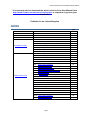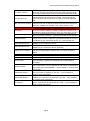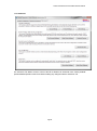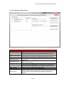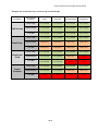
1
Access Controller FB-10 Range User Manual ACCESS CONTROLLER FB-10 MK2 User Manual Page 1 Livewire Connections Access Controller FB-10 User Manual Document Revision 4.1 DOCUMENT REVISION HISTORY DOCUMENT REVISION 1.0 1.1 1.2 1.3 REVISION DATE DESCRIPTION 01 Nov 2008 01 Jan 2009 01 Feb 2009 10 Mar 2009 Initial Preliminary Release Final Release IEC/FCC Approvals Added Static Routing & DAC Control User level restrictions MAC Address reservations FB10-PRO RM version added Italian Language Added Default Firewall Group 2.0 14 Jul 2009 2.1 13 Nov 2009 3.0 06 May 2010 3.1 21 Sep 2010 4.0 22 Dec 2011 4.1 09 Sept 2013 Spend Control Added Lock MAC to IP Added DNS Blocking Added Switch Back Added Overheat protection Added Advanced DHCP Services Automatic Failover Added Bandwidth Management Bandwidth Monitoring QoS New Chassis Layout Updates to QoS Updates to Overheat Temps DHCP Gateway add. GUI Version 1.0.0.0 1.1.0.0 1.2.0.0 1.3.1.4 Release Approve TC TC TC TC JA JA JA JA 2.0.0.5 FR JA 2.0.0.7 TC JA 3.0.0.0 TC JA 3.0.1.1 RB JA 4.0.0.0 RB TC 4.3.0.0 RB Livewire Connections Ltd Unit 41 • Barwell Business Park Leatherhead Road, Chessington, Surrey KT9 2NY United Kingdom Tel +44 (0) 207 9740 900 • Fax +44 (0) 207 9740 949 ALL RIGHTS RESERVED Information in this document is subject to change without notice and does not represent a commitment on the part of Livewire Connections Ltd. Page 2 Livewire Connections Access Controller FB-10 User Manual It is recommended to download the latest revision of the User Manual from http://www.livewire-connections.com/support or request a copy from your distributor. Published in the United Kingdom INDEX 1 Safety Summary 2 Disclaimer 3 Introduction 4 What’s in the Box 5 Installation Guide 6 Administrator GUI 5.1 - Hardware Mounting 5.2 - Typical Installation Network Diagram 5.3 - Connecting your devices 5.4 - Communicating with the FB-10 5.5 - Installing Software 5.6 - Login Prompt 5.7 - Activating your hardware 6.1 - Admin Login 6.2 - System Configuration 6.3 - Call Detail / Control 6.3.1 - Set Service Costs 6.3.2 - Spend Controls 6.4 – Reserv/ed IP Settings 6.5 - Internet Connections 6.6 - Advanced Configuration 6.7 - Group Settings (Firewall Groups) 6.8 - Firewall Settings 6.8.1 - DNS Settings 6.9 - Port Forwarding 6.10 - Static Routes 6.10.1 - QoS Settings 6.10.2 - Bandwidth Monitoring 6.11 - Remote Access 6.12 - User Configuration 6.13 - Default Users 6.14 - Support Information 6.15 - Factory Default Reset 6.15 - Switch Back Settings 6.16 - Automatic Fail Over Page 3 Page 5 6 7 7 8 9 11 11 11 11 12 13 14 16 17 18 20 21 23 24 26 28 29 30 31 33 37 38 39 40 41 42 43 Livewire Connections Access Controller FB-10 User Manual 7 User GUI 8 Appendix 7.1 - User Login 7.2 - User GUI Screenshot 7.3 - User GUI (Restricted) Screenshot 7.4 - User GUI Controls 8.1 - Troubleshooting 8.2 - Connection States Colour Indicators 8.3 - Internet Connections - Templates 8.4 - Interface Drawing 8.5 - Hardware Drawing FB-10 8.6 – Hardware Drawing Rack Mount Kit 9 Technical Specification 10 Further Information Page 4 45 45 46 47 59 51 52 54 55 56 57 57 Livewire Connections Access Controller FB-10 User Manual 1. Safety Summary THE FOLLOWING GENERAL SAFETY PRECAUTIONS MUST BE OBSERVED DURING ALL PHASES OF OPERATION, SERVICE AND REPAIR OF THIS EQUIPMENT. FAILURE TO COMPLY WITH THESE PRECAUTIONS OR WITH SPECIFIC WARNING ELSEWHERE IN THIS MANUAL VIOLATES SAFETY STANDARDS OF DESIGN, MANUFACTURE AND INTENDED USE OF THE EQUIPMENT. LIVEWIRE CONNECTIONS LTD ASSUMES NO LIABILITY FOR THE CUSTOMER’S FAILURE TO COMPLY WITH THESE REQUIREMENTS. GROUND THE EQUIPMENT To minimise shock hazard, the equipment must be connected to an electrical ground. AVOID INTERFERENCE To avoid interference, do not run cables parallel to AC wiring, or near fluorescent lights or other high magnetic or electrical fields. Interference from these types of sources causes equipment to be faulty and will automatically void warranty conditions. AVOID LONG CABLE LENGTHS Any cable longer than 5 meters must be shielded, and all peripheral equipment must be grounded. DO NOT OPERATE IN AN EXPLOSIVE ATMOSPHERE Do not operate the equipment in the presence of flammable gases or fumes. Operation of any electrical equipment in such an environment constitutes a definite safety hazard. DO NOT SERVICE OR ADJUST ALONE Do not attempt internal service or adjustments unless another person, capable of rendering first aid resuscitation, is present. KEEP AWAY FROM LIVE CIRCUITS Operating personnel must not remove equipment covers. Only qualified maintenance personnel must make component replacement and internal adjustment. Do not replace components with the power cable connected. Under certain conditions, dangerous voltage may exist even with the power cable removed. To avoid injuries, always disconnect power and discharge circuits before touching them. DO NOT MODIFY CONFIGURATION OF SOFTWARE This product is a self-contained system installed and configured by a qualified distributor. Modification of software configuration can result in loss of communications and increased airtime bills. Configuration can only be done by or on written instruction by a qualified distributor. ALWAYS FOLLOW MANUFACTURERS ADVICE Suppliers and manufacturers of communications equipment and peripherals provide a wide range of advice on the correct installation of their equipment. The customer should always aim to follow the guidance as provided by suppliers and manufacturers. Page 5 Livewire Connections Access Controller FB-10 User Manual 2. Disclaimer The Access Controller FB-10 and FB-10 PRO are products designed to provide visibility and control to off-vessel data communications. The product has no least cost routing functionality and is designed to aid the operator in switching between different off-vessel data connections. It is the operator’s sole responsibility to ensure that the connection selected is appropriate for the operator’s data requirement. It is also the operator’s sole responsibility to ensure that the connection is manually terminated at the end of each session. Livewire Connections strongly recommends that the operator checks the connection device equipment (such as handset display or modem status lights) to ensure the connection has been terminated. Livewire Connections strongly recommends that for connections that are billed per data used or per time used that additional Service Provider level traffic monitoring and spending control is applied. The use of the inbuilt Firewall is strongly recommended to restrict unwanted outbound traffic. It is the operator’s responsibility to ensure the firewall settings are correctly configured. The use of the inbuilt Spend Control is highly recommended to restrict unwanted traffic. It is the operator’s responsibility to ensure the Spend Control feature is correctly configured. The Automatic Failover feature should be used in conjunction with Switch Back to ensure the primary service is resumed as soon as possible. The Automatic Failover feature should be used in conjunction with Spend Control if the secondary service is charged per Mb or per Min. Livewire Connections Ltd accepts no liability whatsoever for any airtime costs incurred during the use of the Access Controller FB-10, FB-10 PRO & FB-10 PRO RM regardless of howsoever or by whom they have been incurred The Access Controller is based on Debian GNU/Linux which contains free software made available under several licenses like GPL/LGPL and BSD. For the exact distribution terms for each program, please see the description available in individual files at http://192.168.5.1/gpl (the IP address may vary depending on your Access Controller FB-10 configuration). Debian GNU/Linux comes with no warranty from the original software developer, to the extent permitted by applicable law. For any warranty issues, please contact your local distributor from which your Access Controller FB-10 was purchased. Page 6 Livewire Connections Access Controller FB-10 User Manual 3. Introduction Congratulations on the purchase of your new Livewire Connections Access Controller FB-10. This device will manage all of your off-vessel data requirements and allow visibility and control for all your data traffic. The Livewire Connections Access Controller FB-10 can be configured in minutes to manage all your existing connections as well as adding additional firewall user group management, port forwarding, remote WAN to WAN access, spend control, QoS, Bandwidth Monitoring and data statistics. From a simple single page graphical interface it is possible to manage all of your off vessel communications including, but not limited to VSAT, Inmarsat Fleet & Fleet Broadband, Iridium OpenPort, Thuraya DSL, ISDN, GPRS/3G, Off-Vessel WiFi and Shore ADSL. 4. What’s in the box The Access Controller FB-10 is shipped with the following components: Access Controller FB-10 Localized AC/DC Power Supply Mounting Brackets (shelf or Rack mount specified when ordering). Warranty activation form Hardware test certificate Quick Start Guide / Bridge Reference Card Access Controller FB-10 Page 7 Livewire Connections Access Controller FB-10 User Manual 5. Installation Guide 5.1. Mount the hardware in a suitable location using the supplied mounting brackets. The following should be considered when choosing a suitable location: Ventilation – The FB-10 requires good ventilation. A minimum separation distance of 200mm is required from the heat sink on the top of the hardware and around the side vents. If the hardware is to be mounted in a cupboard or enclosure it is necessary to ensure the enclosure has good ventilation or cooling available at all times. There is a fan venting from the left side. It is necessary to ensure the fan is kept free from dust and cleaned when required. Power supply – The FB-10 must be connected to Uninterruptible Power Supply (UPS) / Surge Protector to prevent any damage from inconsistent onboard power. Cable Length – If it is intended to connect Serial devices to the FB-10 it is necessary to consider the maximum cable length recommended by the device manufacturer. Mounting – The FB-10 can be supplied with a Wall Mount/Shelf Kit or 19” Rack mount kit please specify when ordering the brackets you require. If in doubt one of our members of staff can assist you in choosing or recommending mounting solutions. Rack Mounting Brackets Wall/Shelf Mounting Brackets Page 8 Access Controller FB-10 Range User Manual 5.2. Typical Vessel Network Installation Page 9 Access Controller FB-10 Range User Manual 5.3. Connect your off-vessel communication devices via either a Serial (DB-9 connector), Ethernet, or USB to Ethernet* connection. Access Controller FB-10 Interface Diagram: 1 x Vessel LAN Ethernet RJ45 (Port 8) 7 x WAN Ethernet RJ45 1 x Serial 1 x VGA (For Livewire diagnostic use) 2 x USB Front (For approved USB to Ethernet convertor devices only) 2 x USB Rear (For approved USB to Ethernet convertor devices only) *The support for approved USB devices is intended to increase the number of Serial or Ethernet ports by adding a USB to Serial/Ethernet convertor. For a full list of approved USB devices visit http://www.livewire-connections.com/support or contact your distributor. Page 10 Livewire Connections Access Controller FB-10 User Manual 5.4. Connect ‘Vessel LAN’ port (LAN 8) to your onboard network switch or computer. (It may be necessary to use a crossover cable for direct connection to a computer). The default IP address of the FB-10 is 192.168.5.1 5.5. As factory default the FB-10 has DHCP Server enabled. Ensure that your computer is configured to ‘Obtain an IP address automatically’ and ‘Obtain DNS server address automatically’ as per below and navigate to http://192.168.5.1 in any web browser. If the page does not load see Appendix 8.1 – Troubleshooting When the page loads click ‘Click here for the Access Controller software’ button to download the software. Run the Setup file and follow the onscreen instructions. 5.6. From the shortcut on the Desktop or from the Start Menu run the ‘Access Controller’ shortcut. When prompted enter the default admin username (‘admin’) and default admin password (‘password’). Select ‘Admin GUI’ and press OK For further instructions please see either Administrator GUI or User GUI sections later in the manual. . Page 11 Livewire Connections Access Controller FB-10 User Manual 5.7. Hardware Activation Code When you login the first time you may be asked to enter the Hardware Activation Code. This Hardware Activation Code is available by either visiting http://www.livewire-connections.com/activations or by telephoning +44 (0) 208 9740 940 (Monday to Friday 09:00 – 17:00 GMT). You will require the FB-10 Serial Number that is displayed on the Activation Prompt. When you receive the Hardware Activation Code, enter the code (without dashes) and click ‘Activate. Please note that the code is only valid for 48 hours and can only be generated a limited amount of times. Please also note that the code is case sensitive. If you are not asked for the Hardware Activation Code the hardware may have been activated prior to dispatch by your distributor. Page 12 Livewire Connections Access Controller FB-10 User Manual 6. Administrator GUI (Graphical User Interface) 6.1. From either the shortcut on the Desktop or from the Start Menu open the ‘Access Controller’. When prompted enter the default admin username (‘admin’) and default admin password (‘password’). Select ‘Admin GUI’ and press OK. If the login is not successful see Appendix 8.1 – Troubleshooting You will see the following tabs: System Configuration – Configure IP network settings for the Access Controller and Local Area Network (LAN). Managed DHCP Server settings if required. Download Call and System Logs and Configuration Files. Manage Call Spend Control. Internet Connections – Add, Edit and Delete Services (Internet Connections) to be controlled by the Access Controller. Advanced – Optional configuration of Firewall, QoS, DNS Blocking, Port Forwarding, Static Routing, WAN to WAN Remote Access, Sea Tel DAC Control, User configuration, Support and Firmware uploads. Page 13 Livewire Connections Access Controller FB-10 User Manual 6.2. System Configuration The default IP Address for the FB-10 is 192.168.5.1 - by default the FB-10’s inbuilt DHCP server is enabled with a default range of 192.168.5.100 – 192.168.5.200 To change the IP Address select ‘Edit Configuration’ and enter the configuration as below: LAN Configuration Name IP Address Subnet Mask DHCP From To Enter a name for the configuration (Eg Vessel Name). This name will appear on the User GUI. This is the IP address that will be assigned to the Vessel LAN port. Please note, this needs to be in the same IP range as your LAN or you will not be able to access the FB-10. This is the Subnet Mask that will be assigned to the chosen port when selected. Typically this should be 255.255.255.0 If selected the device will provide IP details to those devices set to automatically obtain network settings. This should be switched off if any other device on the network is configured to provide this functionality. WARNING – If you disable DHCP and forget the IP address range you might not be able to access the FB-10 without a Factory Reset If DHCP is enabled this specifies the first IP Address issued from the FB-10 to devices on the network. This range should not be used by any other devices on the network otherwise IP Address conflicts may occur. If DHCP is enabled this specifies the last IP Address issued from the FB-10 to devices on the network. This range should not be used by any other devices on the network otherwise IP Address conflicts may occur. Page 14 Livewire Connections Access Controller FB-10 User Manual Use other DNS IP Address Specify Gateway Configuration Login Revert Timeout Reserved IP Settings Edit Configuration Cancel Changes Apply Configuration If selected, the IP Address defined below will be provided as the primary DNS server, for instance if you have an internal Windows server or perhaps prefer to use public DNS such as 8.8.8.8. If not, then the IP of the Access Controller will be used. You also have the option to define a secondary DNS server should your primary be unreachable. When checked this allows you to use the input box below and add a Gateway that will be provided via DHCP to client machines, this for instance could be a Router or Layer 3 switch on your internal network should you have a structured network with various VLAN’s. If this option is left unchecked then the Access Controller will be specified as the network gateway for all clients. Time limit (in seconds) within which a user must re-login to the Access Controller after changes have been committed before they are automatically undone. This is to prevent loss of connectivity due to errors in entering the IP configuration. The default setting is 90 seconds. This can be disabled by selecting ‘Disabled’ from the drop down. Allows IP addresses to be reserved or locked to specific MAC addresses. See section 5 for details. Edit the LAN Configuration settings Cancel any unapplied changes to the IP configuration. Commit changes to the Access Controller. It will be necessary to login again within the number of seconds defined in the Configuration Login Revert Timeout or the applied changes will be lost. Download Center Reset Counters Reset to zero the volume and time counters for all services. Note: This cannot be undone although the Call Logs will be unaffected. Call Detail / Control Enables the user to download a Call Log that can be exported into Excel or similar spreadsheet application via CSV file, for call analysis. Also enables users to set spending limits for each service. See section 6.3.2 for details. Download Log Download Config Enables the user to download a Technical Log for diagnostic testing & troubleshooting. (see Appendix 8.1 – Troubleshooting. The log will open in the users default web browser. Enables the user to download a Configuration file (.cfg) to enable the user to backup and transfer all configurable settings onto the FB-10. Page 15 Livewire Connections Access Controller FB-10 User Manual 6.3. Call Detail / Control Call Logs All Records All Records Starting All Records Between Start Date End Date All Details Get Call Log Save CSV Date/Time Action Group Service Data Vol Duration Cost Select all call records. Please note the call records older then 6 months will automatically be deleted. Select all call records from the Start Date. Select all call records between the Start Date and the End Date. Select the start date. Please note the call records older then 6 months will automatically be deleted. It is possible to enter the Start Time as well as the start date by manually typing in the field in 24 hour format. Select the end date. Filter between successful calls and failed calls. A failed call is when a call failed to connect during the dialup procedure. Preview the results of your query in the table Export the results of your query to a .CSV file. This can then be imported into Microsoft Excel or other spreadsheet applications for further analysis. Logs the date and time that the call was initiated. Logs the user action to initiate or terminate a call. Logs the Firewall Group that was applied at the time of the call. Logs the type of service (Internet Connection) that was placed. Logs the amount of Data that was both transmitted and received in the call. Logs the amount of time that the call was active. (in Seconds) Estimates the cost of the call based on the User Configured Service Costs (see below) Page 16 Livewire Connections Access Controller FB-10 User Manual Call Costs Set Service Costs Spend Controls Zero Current Usage Delete Control Apply Changes Cancel Changes Allows users to enter unit call costs based on either time or volume for each service. See section 6.3.1 Allows users to configure spending limits and alert monitors. See section 6.3.2 Resets selected Spend Control - See section 6.3.2 Deletes selected Spend Control - See section 6.3.2 Apply Changes to Spend Controls and Service Costs - See section 6.3.2 and See section 6.3.1 Cancels Changes to Spend Controls and Service Costs - See section 6.3.2 and See section 6.3.1 6.3.1.Call Detail / Control - Set Service Costs Set Service Costs Set Service Costs Apply Changes Discard Changes No. Service Charge on Time Charge on Data Cost Units Select to enter the Service Cost configuration. Apply changes made to the Service Costs entry form. Cancel changes made to the Service Costs entry form. This is a sequential number assigned to each service. This will list the services that are currently configured on the FB-10 Check if the service selected is charged by time. Check if the service selected is charged by data used. This is the cost of the service applied either per Minute, per Megabyte or per Megabit. If the service has a fixed monthly cost, enter the cost as zero. The monetary units of ‘Cost’ are notional and therefore could be $, £, € etc. However it is necessary to convert each of the different Service Costs into the same currency so that the Spend Controls can calculate based on a monetary value. See section 6.3.2 Use the drop down menu to define the units or either time or volume to estimate the call cost. Volume can be measured in Megabytes or Megabits. Time is only measured in Minutes. Page 17 Livewire Connections Access Controller FB-10 User Manual 6.3.2. Call Detail / Control – Spend Controls Spend Controls Spend Controls Zero Current Usage Delete Control Apply Changes Cancel Changes Service Period Select to enter the Spend Control configuration. This resets the highlighted Spend Control usage to Zero. Example: A rule is configured that allows a Service to use 50Mb per month starting from 1st Feb 2013 before the Service is Blocked. If on the 18th Feb 2013 the rule is triggered, the operator can login to the Admin GUI and select ‘Zero Current Usage’. This will reset the usage to zero allowing a further 50Mb to be used before 28th Feb 2013. On the 1st March 2013 the Usage counter will reset to zero to allow a further 50Mb in the next month. An alternative option for the operator would be to change the Volume for the rule to allow say 60Mb. However, in this case the Volume for all following months would also remain at 60Mb. This deletes the selected Spend Control rule. Apply changes made to the Spend Controls entry form Cancelled changes made to the Spend Controls entry form Select the service to which you want the Spend Control rule to apply. In addition you can select ALL SERVICES in which the rule will be applied across all the Internet Connections (usually with units of Service Cost). Use the drop down menu to select between: Per Call – Rule is applied to a single call. i.e. Time or Data is calculated between when the Service button is selected on the User GUI and when either the Disable button is selected or another (or the same) Service is selected. Daily – Rule is applied to calls placed on a single day from 00:00 to 23:59. The Usage is reset at 00:00 on the following day. (All times UTC) Weekly – Rule is applied to calls placed in a single 7 day week from 00:00 on the day specified in the Start calendar. The Usage is reset at 00:00 on the same day for the following week. (All times UTC) Monthly – Rule is applied to calls placed in a single calendar month from 00:00 on the date specified in the Start calendar. The Usage is reset at 00:00 on the same calendar date for the following month. (All times UTC) Page 18 Livewire Connections Access Controller FB-10 User Manual Start Volume Units Action Firewall Group Usage Use the calendar to select the day (for Weekly Periods) or Date (for Monthly Periods) to which the rule applies. It is not necessary to set the Start date for Per Call or Daily rules. This is the volume of data or time that must be reached for the Action to be applied. The units depend on the Unit selected in the Units cost column. Use the drop down menu to select between: Service Cost – Action is triggered when specified Volume of Service Cost is reached in the set Period as defined in ‘Set Service Costs’ – See section 4.1. The monetary units of ‘Cost’ are notional and therefore could be $, £, € etc. However when using ALL SERVICES as the selected Service it is necessary to convert each of the different Service Costs into the same currency. Minutes – Action is triggered when specified Volume of Time (in Minutes) is reached in the set Period. Megabytes – Action is triggered when specified Volume of Data (in Megabytes) is reached in the set Period. Use the drop down menu to select between: Alert – When specified Volume is reached within the specified Period for the specified Service a Pop-Up message box is displayed on all open User GUIs. If no User GUIs are open (See Section 6.5 – No GUI Required) Alert is displayed when the next User GUI is opened. Data will continue to be allowed if no User GUI is open. If more than 1 User GUI is open then the Pop-Up message can be accepted by any user and will then disappear on all User GUIs. Drop Call – When specified Volume is reached within the specified Period the specified Service will be set to Disabled. This will occur even if no User GUIs are open. This Action is normally used in ‘Per Call’ Periods. Apply Firewall – When specified Volume is reached within the specified Period the Firewall Group chosen will be applied for the specified Service. This will occur even if no User GUIs are open. Block Service – When specified Volume is reached within the specified Period the specified Service will be set to Disabled. If there is an attempt to reconnect the Service a Pop-Up message box is displayed on all open User GUIs stating the Service (or ALL SERVICES) are barred. The Services will be barred even if no User GUIs are open, although the Pop-Up message will only be displayed when a User GUI is opened and a Service selected. Use the drop down menu to choose the Firewall Group to be applied when ‘Apply Firewall’ Action is triggered. For information on creating Firewall Groups and Firewall rules see Sections 6.7 and 6.8. This is a numerical and graphical display of current usage as a percentage of the allowed usage. When Usage reaches 100% the specified Action is triggered. Page 19 Livewire Connections Access Controller FB-10 User Manual 6.4. Reserved IP Settings Reserved IP Settings MAC Address IP Address Comments Lock IP to MAC Delete Record Cancel All Changes Apply Changes Show/Hide Leases Add Leased System This is the MAC address of the device for which you wish to reserve a IP address (Always give the same address). The formatting should be in the following syntax, example: AA12CC34EE56F (Without Colons) This is the IP address that you want to reserve for that MAC address. This should be a unique address not in used by any other device. Optional comments to identify the device. Example: Fred’s iPhone The MAC Address is a physical address on a device that never changes. If checked the Lock feature prevents a user changing their IP address on their own PCs to circumnavigate Firewall settings. If the user does change their IP they will lose all connectivity to the internet. Deletes the highlighted item. Undo any changes which have not been applied yet. Applies all the unsaved changes which have been made. Display and hide the DHCP lease pane Selecting a row in the DHCP lease pane and selecting ‘Add Leased System’ adds the machine to the reserved IP settings. Here you can add a custom name if you desire such as ‘Captain’ which would make more sense when monitoring your bandwidth. Page 20 Livewire Connections Access Controller FB-10 User Manual 6.5. Internet Connections To add a new service (Internet Connection) select ‘Add New Service’ and enter the configuration as below: The configuration options below will only be visible for the appropriate Interface and Service Template selection. To view all configurable options for each Interface choose Custom from the Service Template. All Services Add New Service Edit Current Service Delete Current Service Undelete Current Service Apply Service Changes Save Changes Cancel Changes Up Arrow Down Arrow Service Name Interface Service Configuration Add a new service to be configured. Edit an existing service to be reconfigured. Deletes the selected existing service. Undelete the selected recently deleted service. Applies new or edited service configuration. Any current active connections will be disconnected. Saves new or edited service configuration (Ready to be Applied). Cancel a new or edited service configuration. Re-order list of services in User GUI. Re-order list of services in User GUI. This is the name to be displayed on the User GUI to represent the Service/Internet Connection (e.g. VSAT). Select the Interface to which the service is connected corresponding to the Interface diagram in Appendix 8.4. Select hardware/connection type based on Service Template selected. Page 21 Livewire Connections Access Controller FB-10 User Manual No Traffic Timeout No GUI Required Min User Level required This is the period of inactivity (no data transfer), in seconds, after which the call will be dropped. Please note: having dropped a call the system will then place a further call if data transfer starts again. If the no GUI required box is checked the service will remain connected even if all user GUIs are closed. This should only be used with fixed cost services such as VSAT to avoid unexpected bills. Minimum User Level required to be able to select this service. If the logged in user has not got the required user level, then the service will not be available for selection. (Text will be shown in red). Ethernet Services IP Address Subnet Mask Default Gateway Preferred DNS server Alternate DNS server Obtain an IP via DHCP Dialup Services Username Password Service APN Number Dialled Initialisation String 1 Initialisation String 2 Port Speed This is the IP address that will be assigned to the selected port when the service is selected. Please note that this needs to be in the same IP range as the device to which you are trying to connect. This is the Subnet Mask that will be assigned to the selected port when the service is selected. Typically this should be 255.255.255.0 This is the Default Gateway that will be assigned to the selected port when the service is selected. Typically this should be the same IP address as your connection device. (e.g. VSAT Modem IP). Enter your Preferred DNS server. Typically this may be the same IP address as your connection device. Enter your Alternate DNS server. Typically this may be the same IP address as your connection device. (Optional) If you are connecting to another Ethernet device that will provide you with the appropriate IP address then you should check this option. This is the username required to authenticate a dialup connection. This is the password required to authenticate a dialup connection. The APN supplied to you by the ISP for the network to which you are connecting. (Typically for GPRS/3G and Fleet Broadband Networks). The number use in dialup connections to connect to the ISP. For some connections it may be required to add a hash symbol (#) after the number (eg Inmarsat MPDS). – Only available on Custom serial connections. This is used for entering a bespoke AT command used to initialise your connection, if required by your ISP. – Only available on Custom serial connections. This is used for entering a second bespoke AT command used to initialise your connection, if required by your ISP. – Only available on Custom serial connections. This sets the serial port speed required to connect to your serial device. Typically this should be left at 115200. – Only available on Custom serial connections. Page 22 Livewire Connections Access Controller FB-10 User Manual 6.6. Advanced The Advanced Tab allows access to some of the FB-10 features for advanced users. Factory defaults permit standard operation of the FB-10 without making any changes under the Advanced Tab. Page 23 Livewire Connections Access Controller FB-10 User Manual 6.7. Group Settings (Firewall Groups) Firewall Groups Add New Group Edit Current Group Delete Current Group Apply Group Changes Set Default Group Default Start Group Save Default Group Group Name Cancel Changes Save Changes Existing Rules Add a new Group to which Firewall Rules can be applied. Edit an existing Group to which Firewall Rules are applied. Note all rules applied to this group under Firewall Settings will be retained. Delete an existing Group to which Firewall Rules are applied. Note all rules applied to this group under Firewall Settings will be removed. Commit any changes to the Access Controller. Change the default firewall group (Activates ‘Default Start Group’ drop down menu). Drop down list of firewall groups. The select group will be used after a restart or loss of power. Exits out of the Default Group option Enter name of the Firewall Group (eg ‘Crew Access’, ‘Email Only’ etc). This is the name that will appear in the dropdown on the User GUI. Cancels the current changes to the Group Name. Saves the current changes to the Group Name. Yes/No – Shows if the group has any Firewall Rules are applied under Firewall Settings. Note: If you delete a group all existing rules applied to that group under Firewall Settings, DNS settings & QoS will be removed. Page 24 Livewire Connections Access Controller FB-10 User Manual Example use of internet access control using Firewall Groups Group Name Full Access Email Only Restricted Crew Owner Onboard Users based on IP Address VSAT Shore WiFi Fleet Broadband 3G Roaming Owner Laptop FULL ACCESS FULL ACCESS FULL ACCESS FULL ACCESS Captain Desktop FULL ACCESS FULL ACCESS FULL ACCESS FULL ACCESS Crew WiFi FULL ACCESS FULL ACCESS FULL ACCESS FULL ACCESS Owner Laptop FULL ACCESS FULL ACCESS FULL ACCESS FULL ACCESS Captain Desktop EMAIL ONLY EMAIL ONLY EMAIL ONLY EMAIL ONLY Crew WiFi EMAIL ONLY EMAIL ONLY EMAIL ONLY EMAIL ONLY Owner Laptop FULL ACCESS FULL ACCESS FULL ACCESS FULL ACCESS Captain Desktop FULL ACCESS FULL ACCESS EMAIL ONLY NONE Crew WiFi FULL ACCESS FULL ACCESS NONE NONE Owner Laptop FULL ACCESS FULL ACCESS FULL ACCESS FULL ACCESS Captain Desktop FULL ACCESS FULL ACCESS EMAIL ONLY EMAIL ONLY Crew WiFi NONE NONE NONE NONE Page 25 Livewire Connections Access Controller FB-10 User Manual 6.8. Firewall Settings (Traffic filtering) Firewall Settings Group Name Add New Rule Edit Current Rule Delete Current Rule Apply Rule Changes No. Up Arrow Down Arrow Entering a Rule Rule Name Action Protocol Select Group Name you wish to View/Configure as defined in Firewall Groups. Add a new rule to be configured. Edit configuration of an existing rule. Delete the configuration of an existing rule. Applies saved rule changes to the FB-10. This is the number that is automatically assigned to the rule. The Firewall Rules are applied in this order (i.e. Top to Bottom). Select a rule then change the order in which the rules are applied (Applies rules from Top to bottom). Select a rule then change the order in which the rules are applied (Applies rules from Top to Bottom) This is the name given to the current rule (E.g. Email Server Only). Select required Action for rule. ACCEPT (Accept the packet), DROP (Silently drop the packet without sending an ICMP reject message), REJECT (Reject the packet and send an ICMP reject message). Select protocol for the rule to be applied (TCP, UDP, ICMP, ALL, DNS) NOTE: The ALL option does not cover DNS queries as they are relayed via the Access Controller and therefore require a separate rule to allow/block. NOTE: The DNS protocol only blocks DNS requests for clients using Page 26 Livewire Connections Access Controller FB-10 User Manual Source IP Source Port Destination IP Destination Port Selected Services Other Services Add Remove Save Changes Cancel Changes the Access Controller as their only DNS server. Public DNS servers won’t be blocked, use a normal TCP/UDP port 53 block for this. IP address of the packet data source. Leaving blank will assume all source IP addresses. IP addresses can be entered as singles (192.168.5.50) or using ranges (192.168.5.55-192.168.5.60). Multiple ranges and/or IPs can be entered using commas (192.168.5.50,192.168.5.55-192.168.5.60). The IP used here can be an internal LAN IP or external internet IP. Port of the packet data source. Leaving blank will assume all ports. Ports can be added in the format 110 or 110,143 IP address of the packet data destination. Leaving blank will assume all destination IP addresses. IP addresses can be entered as singles (192.168.5.50) or using ranges (192.168.5.55-192.168.5.60). Multiple ranges and/or IPs can be entered using commas (192.168.5.50,192.168.5.55-192.168.5.60). The IP used here can be an internal LAN IP or external internet IP. Port of the packet data destination. Leaving blank will assume all ports. Ports can be entered as singles (110) or using ranges (1024-2024). Multiple ranges and/or ports can be entered using commas (110,10242024). Services (Internet Connections) for which the rule will be applied. Services (Internet Connections) configured on the FB-10 for which the rule will not be applied. Add Service for which the rule will be applied. Remove Service for which the rule will be applied. Save changes for the current rule. Cancel changes for the current rule. Important Note: The default action is to allow all traffic. Most common setup scenarios usually therefore have a ‘Block All’ REJECT/DROP rule at the bottom. If there is not a single REJECT/DROP rule in the list then this is very likely to be incorrectly setup. Livewire Connections recommends that the firewall is setup by an experienced network administrator as incorrect usage/setup will allow unwanted data to leave the vessel. Page 27 Livewire Connections Access Controller FB-10 User Manual 6.8.1. DNS Settings DNS Settings Group Name Add New Rule Edit Current Rule Delete Current Rule Apply Rule Changes Domain Specify Redirect Destination IP Comment Selected Other Services Add Remove Save Changes Cancel Changes Select Firewall Group to which the DNS rules will apply. Add a new rule to be configured. Edit configuration of an existing rule. Delete the configuration of an existing rule. Applies saved rule changes to the FB-10. Enter the domain that you want to restrict (E.g. facebook.com it is best to enter all variants such as facebook.co.uk). Select to redirect users to the ‘Destination IP’ (below) address if the user attempts to access a domain that is blocked. If this is not selected the user is presented with a default ‘DNS blocked’ message This is the IP address of a website to which users will be redirected if ‘Specify Redirect’ is selected. This is a description for the rule that is only visible in the Admin GUI Services (Internet Connections) for which the rule will be applied. Services (Internet Connections) configured on the FB-10 for which the rule will not be applied. Add Service for which the rule will be applied. Remove Service for which the rule will be applied. Save changes for the current rule. Cancel changes for the current rule. Important Note: DNS settings limitation DNS Blocking will only be applied if the users are using the FB-10 to manage DNS and it is their only DNS server. If users have either external DNS servers specified (can be blocked through the firewall) or pages have been DNS cached while on other external networks (E.g. Internet Café) then it may be still possible to access restricted domains. Web browsers also tend to cache DNS lookups for a longer time. This feature is mainly designed to be used to block other applications like Anti-Virus/Windows Updates or to block certain websites all the time. Page 28 Livewire Connections Access Controller FB-10 User Manual 6.9. Port Forwarding Port Forwarding Add New Rule Edit Current Rule Delete Current Rule Apply Rule Changes Entering a Rule Rule Name Protocol Destination IP Source Port Destination Port Selected Services Other Services Add Remove Save Changes Cancel Changes Add a new rule to be configured. Edit configuration of an existing rule. Delete the configuration of an existing rule. Applies saved rule changes to the FB-10. This is the name given to the current rule (Eg Video Conferencing). Select protocol for the rule to be applied (TCP, UDP, ICMP, GRE). IP address of the device on the LAN to which traffic on the specified port will be forwarded. Incoming Port number. Enter the port number which will be used for the external incoming connection. Ports can be entered as singles (110) or using ranges (1024-2024). Destination Port number. Enter the port number that the device on the LAN is expecting an incoming connection. Ports can be entered as singles (110) or using ranges (1024-2024). Services (Internet Connections) for which the rule will be applied. Services (Internet Connections) configured on the FB-10 for which the rule will not be applied. Add Service for which the rule will be applied. Remove Service for which the rule will be applied. Save changes for the current rule. Cancel changes for the current rule. Note for port forwarding to work correctly you will need a Public IP on your internet connection, this will then be used from the outside of the vessel to contact the Access Controller on board. Page 29 Livewire Connections Access Controller FB-10 User Manual 6.10. Static Routing Static Routing Add New Rule Edit Current Rule Delete Current Rule Apply Rule Changes Entering a Rule Rule Name Rule Type Destination IP Netmask: Via Gateway: Gateway IP: Save Changes Cancel Changes Add a new rule to be configured. Edit configuration of an existing rule. Delete the configuration of an existing rule. Applies saved rule changes to the FB-10. This is the name given to the current rule (Eg AV VLAN). Static Routes allow for NET rules (Routing to a Network Range) or HOST rule (Routing to an individual IP address) Define the IP address to which the Static Rule will route. If host type is a NET rule, then enter the IP address of the start of the range (192.168.4.0). Define the Net to which the Static Rule will route. (255.255.255.0 for entire subnet). Check to define if your want the Static Route to route via a Gateway. Define the IP address of the gateway to which the Static Rule will route (Usually an internal LAN router or Layer 3 Switch, this should be on the same subnet as the FB10 LAN). Save changes for the current rule. Cancel changes for the current rule. Page 30 Livewire Connections Access Controller FB-10 User Manual 6.10.1.QoS Settings QoS Settings Add New Rule Edit Current Rule Delete Current Rule Copy Rule Apply Rule Changes Entering a Rule Rule Name Service Upload Speed Download Speed Selected Firewalls Other Firewalls Add a new rule to be configured. Edit configuration of an existing rule. Delete the configuration of an existing rule. Copies ‘Classes’ percentage values and IP range(s) from a previous rule for you to use in a new rule. Applies saved rule changes to the FB-10. This is the name given to the current rule (E.g. Crew Restriction). The internet connection that you wish the rule to apply to, this is carried over from your internet connections page. (Ie. VSAT, Fleet Broadband). Estimated Uplink Speed of your selected service. This should be a realistically achievable speed for the service and not simply the maximum stated value, we recommend you perform several speed tests to verify you true speed achievable. Estimated Downlink Speed of your selected service. This should be a realistically achievable speed for the service and not simply the maximum stated value, we recommend you perform several speed tests to verify you true speed achievable. These are the Firewall Groups to which the QoS settings will be applied when enabled and using the specified service. NB. It is not necessary to have any other firewall rules associated with these firewall groups if you only require QoS settings. These are the other Firewalls Groups configured on the FB-10 that do not currently have any QoS settings configured for the selected service. Page 31 Livewire Connections Access Controller FB-10 User Manual Class Min Up (%) Max Up (%) Min Down (%) Max Down (%) Vessels IP Range Save Changes Cancel Changes Top down list, allows you to differentiate bandwidth percentages between IP addresses/Ranges. The minimum upload speed that will be made available for a particular class expressed as a percentage of the overall upload speed. Any cell left blank will be set to a value of 0%. Please note, for correct operation the sum of all Min Up percentages should not add up to more than 100%. The maximum upload speed that will be made available for a particular class expressed as a percentage of the overall upload speed. This can be configured to cap a classes maximum speed or to allow it to utilise unused bandwidth assigned to other classes. To cap a class simply enter a maximum value greater than or equal to your Min Up (%) but less than 100. The higher the maximum value is above the Min Up (%) the more available bandwidth the class will be able to utilise. For full free bandwidth utilisation across all classes the Max Up (%) for all classes should be set to 100. The minimum download speed that will be made available for a particular class expressed as a percentage of the overall download speed. Any cell left blank will be set to a value of 0%.Please note, for correct operation the sum of all Min Down percentages should not add up to more than 100%. The maximum download speed that will be made available for a particular class expressed as a percentage of the overall upload speed. This can be configured to cap a classes maximum speed or to allow it to utilise unused bandwidth assigned to other classes. To cap a class simply enter a maximum value greater than or equal to your Min Down (%) but less than 100. The higher the maximum value is above the Min Down (%) the more available bandwidth the class will be able to utilise. For full free bandwidth utilisation across all classes the Max Down (%) for all classes should be set to 100. The IP range / individual IPs included within each class. This can be from different subnet ranges and across VLANs. IP addresses can be entered as singles (192.168.5.50) or using ranges (192.168.5.55-192.168.5.60). Multiple ranges and/or IPs can be entered using commas (192.168.5.50,192.168.5.55-192.168.5.60). Please note, any IP not specified here will be handled by the Default Class. Save changes for the current rule. Cancel changes for the current rule. Important Note: QoS Limitations. Please note, for the QoS feature to work as specified when using services with highly volatile bandwidths you must configure the upload speed to be a realistically achievable level or cap non-essential classes. In reality if you have a contended 1024kbps maximum downlink speed you are unlikely to always get the full 1024kbps, be this due to network traffic, bad weather or poor installation of RF Equipment. We recommend that you perform speed tests to ascertain your average download and upload speeds. Page 32 Livewire Connections Access Controller FB-10 User Manual 6.10.2.Bandwidth Monitoring. Live and historical monitoring of the current bandwidth (speed) and data volume usage can now be accessed from the Access Controller web interface. The web interface can now be easily accessed from within the User GUI by Clicking on the picture of the FB10 Access Controller unit circled below: After the webpage has opened you will find the links to the Bandwidth logs and graphs in the middle of the web page. To view your entire networks usage of your internet connection; use the ‘Bandwidth Usage Graph’ hyperlink. To view usage on an individual level (Per; IP address/User) then use the ‘Bandwidth Usage Logs’ hyperlink. Page 33 Livewire Connections Access Controller FB-10 User Manual Bandwidth Usage Logs: On the following page you can organise and select how you want to display the Internet connections usage. You can go to individual PC’s and see who or what is taking up your bandwidth. Access Controller Bandwidth Monitor Period Historic time period that you want to see the data usage over. Order By Allows you to sort the table view by IP or Data Usage. Refreshes the webpage to show changes in data usage since webpage Reload Data was opened. Select from ALL to see total activity or click on an individual PC/IP Computer (I.e:192.168.5.91) to see that devices usage of the internet bandwidth. Total data downloaded by device in selected time. Displayed in Megabytes Download (MB) as this is a volume of data rather than speed measurement and will show how much data has been downloaded from the internet. Total data uploaded by device in selected time. Displayed in Megabytes as Upload (MB) this is a volume of data rather than speed measurement and will show how much data has been uploaded to the internet. Total data usage by device(s) expressed as a volumetric figure in Combined (MB) Megabytes. Combines the downloaded and uploaded data via the Access Controller to/from the internet. Page 34 Livewire Connections Access Controller FB-10 User Manual Bandwidth Usage Graph: This page shows you the ‘Live’ overall usage of your internet service. Page 35 Livewire Connections Access Controller FB-10 User Manual Access Controller Live Bandwidth Usage (Graphs) Historic time period that you want to see the data usage over. For Live and Last 15 Minutes the graph shows speed in kilobits per second (kbps) Period whilst for periods over 15 minutes the chart shows total data volumes in Megabytes (MB) measured during that time period This is the rate at which data was sampled in order to create the graph / chart. At the highest rate the data is sampled once every 10 seconds and an average speed is calculated based on the volume of data transferred Data Sample Rate during that time. NB. As speeds are averaged over the 10 seconds they will not capture the maximum data speed at a single point in time but will provide a smoothed representation of speeds attained. Displays the bandwidth usage for Live or Last 15 minutes in kilobits per Speed (kbps) second (kbps). Once a historic value over 15 minutes has been selected in the Period Volume (MB) drop down box then the vertical axis will show volume in Megabytes (MB) rather than speed. The horizontal axis will change dependant on Period selected to reflect a Time (UTC) suitable time interval (This time is synchronised with the Bios clock on the FB10 motherboard and not the local time). Page 36 Livewire Connections Access Controller FB-10 User Manual 6.11. Remote Access Remote Access Tick check box to enable remote GUI access. Enabling GUI Access will allow off vessel configuration of your Access Controller via a public IP. DAC access allows you to remotely configure a Sea Tel DAC Antenna Control Unit directly connected to the FB-10 using DACRemP IP Software (Port 8889) supplied by Sea Tel. This feature can be used Open DAC Access remotely if the Open GUI Access is enabled. On higher latency connections the Timeout and Pacing values in DACRemP need to be changed. Choose the Serial Port that is used to connect the FB-10 to the DAC M&C Port. Please note: Enabling Remote DAC Support on a selected port will delete any service currently assigned to that port. To ensure no Choose DAC Port further services are configured on that port it will not appear in the port list under services again until this function is disabled. Your Admin GUI will be restarted automatically and any changes that have not been applied will be lost. Applies changes to the Open DAC Access and Open GUI Access Apply Changes check box. Remote WAN to WAN Access This is the time (in seconds/minutes) after which the remote user will be Disconnect Time disconnected from the FB-10 after no further user intervention. Shore Connection This is the connection used to establish your shore link. Inspected WAN This is the device you are looking to query, for diagnostic/configuration Service remotely. This is the IP address that will be assigned to your shore connection when forwarded to the other WAN port. Please note, this needs to be in IP Address the same range as the device you are trying to connect to but must not be the same as your WAN interface. Enables WAN to WAN access. Enabling will establish an internet connection and will route incoming traffic to an alternative WAN Enable Access Button interface. (E.g. Your VSAT will route to the Shore WiFi, so a technician can come in on the VSAT and repair or configure the Shore WiFi,). This will reset the disconnect time to the original setting, allowing more Extend Timeout time for the remote user to use WAN to WAN inspection. Disable Access This terminates the WAN to WAN session. Open GUI Access Page 37 Livewire Connections Access Controller FB-10 User Manual 6.12. User Configuration Password Configuration Add New User Add a new user to be configured. Edit Current User Edit configuration of an existing user. Delete Current User Delete the configuration of an existing user. Apply User Changes Commit changes to the Access Controller. Adding a User User Name This is the user name given to the current user to login (E.g. Captain) Apply access level to user account. The following levels are available, User Level Password Confirm Password Allow Password Change At Logon Save Changes Cancel Changes ADMIN - Allows access to Admin & User GUI USER - Allows access only to the User GUI USER RESTRICTED - Allows access only to the User GUI. USER FIREWALL GROUP - Allows access only to the User GUI (Firewall cannot be disabled/enabled. However it can be changed) USER NO FIREWALL – Allows access only to the User GUI (Firewall cannot be changed, disabled or enabled) Further restrictions can be applied on individual services. See the “Min User Level required” option in Section 6.5. This is the password associated with the user name. The password is case sensitive. The chosen password has to be entered again to be verified If selected this allows a new user to change the login password after the new user’s initial login. The password change prompt will only appear when the user logs in for the first time. This is to allow an administrator to setup a user account and then for a user to select their own password. Save changes made to the selected user. Cancel changes made to the selected user. Page 38 Livewire Connections Access Controller FB-10 User Manual 6.13. Default Users The follow user accounts are setup by default on the FB-10: Username: Password: User Level: admin password ADMIN Username: Password: User Level: user password USER When you create a new user and have the ‘Allow Password Change at Logon’ ticked, you will see the above password change prompt. This is to allow an administrator to setup a user account and then a user to select their own password. Page 39 Livewire Connections Access Controller FB-10 User Manual 6.14. Support Information Support Information Firmware Version Serial Number This is the current firmware version on the unit. This is the software serial number of the Access Controller. This is a link to the support area of the Livewire Connections website. Online Support (Internet access required). Manuals (Offline) This is a link to the user manual (stored on the FB10). Enable Tool Tips Enables helpful tool tips in the Admin GUI. User GUI Size Change the size of the User GUI for different resolution screens. Change the language of the User GUI. (More languages to be released User GUI Language soon). Change the language of the Admin GUI. (More languages to be Admin GUI Language released soon). Apply Changes Applies changes made to the GUI Settings above. Current Connections Details This states the IP address received by the current connection in use. If IP Address: it says N/A then the values can not be retrieved, most likely cause is that no service is selected in the User GUI. Netmask: This states the Netmask being applied to the current connection. Gateway: This states the Gateway being used by the current connection. DNS 1: This states the Primary DNS being used by the current connection. DNS 2: This states the Secondary DNS being used by the current connection. Refresh Details Use this button to refresh the current connection details page. Software Updates Details Enables the FB-10’s Firmware to be upgraded. Firmware uploads and Upload Firmware installation instructions are released at http://www.livewireconnections.com/support This allows users to upload previously downloaded configuration. Upload Configuration Please note that you download configuration on the System Configuration page. Restore Factory This restores all configuration changes back to the default factory Defaults settings. The default factory IP address is 192.168.5.1 Restart Access This restarts the Access Controller. Controller This allows you to turn off/on the overheat protection which is built into Disable/Enable the Access Controller. It is highly recommended that you keep the Overheat Shutdown Overheat Shutdown enabled. (If overheat shutdown is disabled you may void you product warranty, please contact Livewire for further Page 40 Livewire Connections Access Controller FB-10 User Manual Current Temperature information). This will display the current temperature of the Hard Drive, Processor and System board (Note that if you have a Solid State Hard Drive installed then the Hard Drive temperature will not be displayed). Current Temperature Screen: 6.15. Overheat Protection A built in feature of the Access Controller is the Overheat Shutdown. This feature detects when the internal temperature of the Access Controller gets excessively high, and then shuts down the system in a controlled manner before any hardware damage occurs. If you are experiencing these Overheat shutdowns and the ambient temperature is not in excess of 35 degrees Celsius, then your Access Controller is situated incorrectly where is insufficient airflow? Livewire Connections strongly recommends you keep the feature enabled. You may invalidate your warranty by disabling this feature; it is there only for diagnostic purposes or in emergencies. 6.16. Hardware Factory Default Reset It is possible to reset the FB-10 to factory defaults by pressing the Power Button on the front of the FB-10 5 times within 5 seconds. If successful the FB-10 will beep several times before resetting. The factory reset can be cancelled by pressing the button a further 5 times before the beep sequence ends. Page 41 Livewire Connections Access Controller FB-10 User Manual 6.17. Access Controller Switch Back You need to have a public IP for your Primary Service, typically a VSAT. When the Primary service is out of range or in blockage, using your User GUI, you would manually connect to the internet using an alternative service. Assuming you have setup the switch back for the service, the Access Controller will continually check to see when your Primary Service is back online, it does this in the form of a ‘Ping’. Once the Access Controller receives 12 successive ping responses in a row, which are sent 10 seconds apart, it will revert the internet connection back to the Primary Service. You will see your user GUI change automatically: Switch Back Settings Primary Service Primary Service Public IP Switching Services Number of Pings Apply Changes This is the service you want to automatically switch to when available. This is the Public IP address of the Primary Service, (Normally public IP address of VSAT Modem). It is essential this IP address responds to pings from the internet. The primary service must not be firewalled to prevent pings from reaching the specified IP address for testing the internet connectivity. Here you can select which of your other internet and communication services you wish to automatically revert back to your Primary Service, when the primary service becomes available. This is the number of consecutive pings that need to succeed before the service is automatically switched back to the primary service. The active Switching Service will ping the IP of the Primary Service constantly and switch after the specified number of consecutive pings have been successful. Applies changes made Automatic Failover settings to the Access Controller. Page 42 Livewire Connections Access Controller FB-10 User Manual 6.18. Access Controller Automatic Failover Automatic Failover is a feature that if enabled allows the Access Controller to automatically switch to a secondary WAN connection in the event the primary connection suffers a loss of services. This operated by constantly pinging a shore side IP address (normally the ISP’s DNS server or similar). The ping is constantly sent from the Access Controller every 10 seconds. After a pre-determined number of unsuccessful pings (configurable as ‘Number of Pings’) the Access Controller will disconnect the Primary service and activate the Failover service. If service to the primary connection is restored Automatic Failover settings alone will not revert to the primary service unless in conjunction with Switch Back. Automatic Failover Primary Service Failover Service IP Address to Ping Number of Pings Enable Automatic Failover Apply Changes This is the service you wish to use as the primary service (eg VSAT) This is the service you wish to use when the primary service does not have an internet connection. (eg Fleet Broadband) This is the IP address of a shore based server you wish to constantly ping to test internet connectivity. This is the number of consecutive pings that need to fail before the service is automatically switched. The Access Controller will ping the specified server once every 10 seconds. When check the Automatic Failover feature is enabled. Any loss in internet connectivity with the primary service will result in the automatic switching to the Failover Service. IMPORTANT NOTES: The Automatic Failover feature should be used in conjunction with Switch Back to ensure the primary service is resumed as soon as possible. The Automatic Failover feature should be used in conjunction with Spend Control if the secondary service is charged per Mb or per Min. Applies changes made Automatic Failover settings to the Access Controller. Page 43 Livewire Connections Access Controller FB-10 User Manual Automatic Failover must be used with extreme care to avoid excessive airtime bills. The Automatic Failover service should be used in conjunction with Switch Back to ensure the primary service is resumed as soon as possible. The Automatic Failover service should be used in conjunction with Spend Control if the secondary service is charged per Mb or per Min. SIM provider level spend controls should always be used in addtion to any onboard spend control. The primary service must not be firewalled to prevent pings from reaching the specified IP address for testing the internet connectivity. If the primary service is charged per Mb small data charges will apply for the monitoring of the primary service (approx 1kbyte/min). Automatic Failover will prevent ‘No Traffic Timeout’ feature triggering and therefore it is not recommended when the primary connection is pay per minute. If the shoreside IP address used becomes unavailable the service will switch even if there is an good internet connection on the primary connection. Page 44 Livewire Connections Access Controller FB-10 User Manual 7. User GUI (Graphical User Interface) 7.1. User Login From the shortcut on the Desktop or from the Start Menu run ‘Access Controller’. When prompted login using the default username (‘user’) and default user password (‘password’). Select ‘User GUI’ and press OK. If the login is not successful see Appendix 8.1 – Troubleshooting 7.2. User GUI Page 45 Livewire Connections Access Controller FB-10 User Manual 7.3. User GUI (Restricted Access) Example: The logged in user above has too low permissions to select the Fleet ISDN and Fleet MPDS service. The user is also a “No Firewall” user so they cannot disable the Firewall, but they can change it. Example: The logged in user above has the same permissions as the previous Example. But here the user’s firewall permission is set to “Firewall Group” so that the user can change it, but not disable/enable it. Page 46 Livewire Connections Access Controller FB-10 User Manual 7.4. User GUI Controls 10 #1 Service Activation Button #2 Disabled Button #3 Firewall Group Select #4 Restrict Access Button #5 Volume & Time Counter #6 Current State Status #7 WAN Status Indicator #8 Connection Icon Select to activate named service. The box colour will change as follows: See Connection State Colour Indicators Select to disconnect all services. Select a Service Activation Button (#1) to reconnect a service. Use the drop down to select which Firewall Group will be applied. Select to apply preconfigured Firewall Settings for the selected Firewall Group (#3). A ‘wall’ icon will appear across the LAN Status Indicator (#9) Counter displays the volume (measured in Gigabytes, Megabytes & Kilobytes) and time (measured in Days, Hours, Minutes and Seconds) of data measured at the WAN interface. (Note this will include local data between the Access Controller and the Modem device). Displays information regarding the current connection status. Error message will also be displayed here. See Troubleshooting Displays the status of the connection between the Modem Device and the Internet. (GREY: Disconnected GREEN: Connecting/Connected) An icon representing the current connection. The icon used is dependent on the Service Template selected. Page 47 Livewire Connections Access Controller FB-10 User Manual #9 LAN Status Indicator #10 FB10 Image Displays the status of the connection between the Access Controller and the Modem Device. (GREY: Disconnected GREEN: Connecting/Connected) Click on the image to link through to the Access Controller web interface. Page 48 Livewire Connections Access Controller FB-10 User Manual 8. Appendix 8.1. Troubleshooting Issue/Error Message Unable to Login to FB-10 (Message: Unable to connect in Title Bar) Resolution Ensure that your PC is on the same IP range and subnet (default 255.255.255.0) as the FB-10. The default range is 192.168.5.X Click ‘Find’ button on login page to try to automatically locate the FB-10. Ensure that the FB-10 is switched on and power LED is illuminated. If DHCP Server is enabled in the FB-10 (default) ensure that you have ‘Automatically obtain IP address’ selected in your Windows PC network configuration. Ensure that you have connected an Ethernet patch cable securely to the LAN 8 interface of the FB-10. If you are unable to access the FB-10 through the onboard vessel network as a test try to connect directly to the FB-10 with a Cross Over Ethernet cable between your PC and the LAN 8 port. If you have recently changed the IP address of the FB10 wait up to 600 seconds (Max Re Login Time) and try to connect on the original IP address. Try to ping the FB-10 using Windows Command Prompt with the command for the default IP ping 192.168.5.1 and monitor the response. Ensure that you have no Firewall rules on the PC or network that may be preventing access to the FB-10. Power cycle the FB-10 by pressing the power button located on the front of the chassis and restart your PC. Check that the modem device is ready to make a call. Check the device has registered successfully on the network. Check the device has a valid GPS position (If relevant). Check the device has good signal strength and is not blocked. Check that the SIM card has not got a PIN number configured (if relevant) NO CARRIER Page 49 Livewire Connections Access Controller FB-10 User Manual BUSY ERROR The FB-10 cannot dial a connection as the line is busy. Ensure that the device does not have a current call up and that is ready for a call. Unspecified error received from the device. Something is wrong with the terminal, check settings, signal strength or reboot terminal if error persists. The access controller cannot communicate with the terminal. Check that the device is connected to the correct interface port of the FB-10. Check cable connection between the device and the FB10. Non standard error message received from terminal. Unknown cause. Try rebooting the device. Connection lost to Fleet Broadband terminal, could not verify that call was dropped/initialised. Check status of device. A command or message was received from the FB terminal which was not expected. Non-supported terminal manufacture or firmware version. Check device has latest Firmware version available. The access controller cannot communicate with the terminal. Check that the device is connected to the correct interface port of the FB-10. Check cables connection to the device from the FB-10. No Ethernet cable was detected, Ensure the correct cable type is used (Straight/Cross over) and that the device is properly connected. No DHCP server was detected. Reconfiguring service as a static IP address or make sure the DHCP server is switched on in the device’s setup Reboot the device. No response from terminal Unknown CME Error received. Check system log for more details. Call failed during critical stage! Check handset to avoid rogue call! Unexpected message received from terminal. Could not connect to terminal. Check terminals status. No cable/device attached Failed to get DHCP Page 50 Livewire Connections Access Controller FB-10 User Manual The statically configured IP address settings could not be used, verify that they are correct and that they are not already in use by any other device. Standard +CME Errors may be displayed in the FB-10. Please refer to your device documentation to resolve. Failed to initialise IP configuration Other Errors 8.2. Connection State Colour Indicators: Example connection state colour indicator Colour Indicator Connection State Activating Idle Connecting Local Device Connect Authenticating Connected Disabled Error Page 51 Livewire Connections Access Controller FB-10 User Manual 8.3. Internet Connections – Templates Above is an Ethernet based service using the Thrane Fleet Broadband – Background Class template. Above is a Serial based service using the GPRS template which provides only the necessary options for GPRS over serial connections. Page 52 Livewire Connections Access Controller FB-10 User Manual Above is a Serial based service using the Custom template which provides all the configurable options for serial connectivity. Page 53 Access Controller FB-10 Range User Manual 8.4. Interface Drawing Page 54 Livewire Connections Access Controller FB-10 User Manual 8.5. Hardware Drawing – FB 10 without brackets. All dimensions are in mm Page 55 Livewire Connections Access Controller FB-10 User Manual 8.6. Hardware Drawing – FB 10 Rack mounted (19” Rack). Page 56 Access Controller FB-10 Range User Manual 9. Technical Specifications Model FB-10 Dimensions (mm) 250(W) x 180(D) x 52(H) – Without rubber feet. Weight 2.95 Kgs (Packaged Weight) Chassis Material/Colour Ambient Operating Temperature Operating Humidity Power Supply Interfaces Approvals Aluminium/Black/Blue 0 to 40°C 5~95% @ 60°C, non-condensing 12-24V DC input; 19V DC 100–240V AC. 1.5A 50-60Hz power adapter supplied 1 x Vessel LAN (Port 8) 7 x WAN (Ports 1-7) 4 x USB (For Approved devices only) 1 x Serial (RS232) 1 x VGA EN 55022:2006 +A1:2007, Class B EN 61000-3-2:2006 +A1:2009 +A2:2009 (Class D) EN 6100-3-3:2008 EN 55024:1998+A1:2001+A2:2003 IEC 61000-4-2: 2008 IEC 61000-4-3:2006+A1:2007 IEC 61000-4-4:2004 IEC 61000-4-5:2005 IEC 61000-4-6:2008 IEC 61000-4-8:2009 IEC 61000-4-11:2004 FCC 47 CFR PART 15 SUBPART B (Class B) IC ICES-003 Issue 4 10. Further Information 1. Updates For Software, Firmware, User Manual, Demo and FAQ updates visit http://www.livewire-connections.com/support http://www.accesscontroller.co.uk For more information about the Livewire Access Controller FB-10 please contact your local distributor. Product brochures, software demos and pricing can be found at http://www.accesscontroller.co.uk Page 57