1
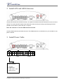
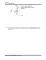
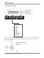
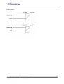
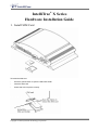
IntelliTrac® X Series
Hardware Installation Guide
1. Install SIM Card
To install the SIM card:
-
Press the yellow button to eject the SIM card holder.
-
Insert the SIM card.
-
Check that it fit into place correctly.
Copyright © 2003 Systems & Technology Corporation
2. Install GPS and GSM Antennas
Connect GPS antenna to the GPS connector. The optimum location for the GPS antenna is on the roof of the
vehicle. The covert and GPS antenna are directional, make sure they are facing up and laying as flat as
possible. Secure them in place with glue, or zip ties.
Note : Do not block or cover the GPS antenna with metal.
Connect GSM antenna to the GSM connector. The GSM antenna is non-directional, so you can hide it in any
place of vehicle.
3. Install Power Cable
1
3
1
3
5
7
9
11
1
3
5
7
9
2
4
2
4
6
8
10 12
2
4
6
8
10
Power
Input
Output
Power Connector
1 : Ground
2 : Ignition Key
3 : BAT. +8V ~ +32V
4 : Mute Control
Copyright © 2003 Systems & Technology Corporation
(1) General Installation (Without immobilizer installed)
Connect Ground(-Black) and BAT(+Red) wires to the battery of vehicle.
Ignition Key (Pink) is no use for general installation.
(2) With immobilizer installed
Caution: Immobilizer only works for 12V
Connect Ground (-Black) and BAT (+Red) to the battery of vehicle.
Connect Ignition Key (Pink) to the IGNITION wire.
4. Install Immobilizer Relay (Optional)
(1) If the wireless relay terminal is same as car original fuel pump (or ignition, or starter) relay terminal,
please just unplug the car original relay, then plug in the wireless relay.
If the
wireless relay terminal is different with car original fuel pump (or ignition, or starter) relay terminal :
Please plug the wireless relay into the spare relay socket, then
a. Connect the socket Black wire to Ground.
b. Connect the socket Red wire to IGNITION
c. Blue & Green wires are for engine disable cutting (ignition or fuel pump or starter…)
Copyright © 2003 Systems & Technology Corporation
(2) For security reason, it is better do NOT install the wireless relay at IGNITION key lock area. May
install the wireless relay in the hood or near the fuel pump or any confidential place for engine
disable cutting.
Copyright © 2003 Systems & Technology Corporation
5. Install Input Cable
1
3
1
3
5
7
9
11
1
3
5
7
9
2
4
2
4
6
8
10 12
2
4
6
8
10
Power
Input
Output
Input Connector
1 : Input1
2 : Input2/ACC
3 : Input3
4 : Input4
5 : Input5
6 : Input6
7 : Input7
8 : Input8
9 : Analog Input1
10 : Analog Input2
11 : Vout +5V
12 : Ground
The Input number 1, 2 are positive triggered inputs and Input number 3, 4, 5, 6, 7, 8 are negative triggered
inputs. If you would like to use power saving function, please connect the Input2/ACC to ACC wire. The
analog inputs are reserved.
Copyright © 2003 Systems & Technology Corporation
Positive Trigger:
Negative Trigger:
Copyright © 2003 Systems & Technology Corporation
6. Install Output Cable
1
3
1
3
5
7
9
11
1
3
5
7
9
2
4
2
4
6
8
10 12
2
4
6
8
10
Power
Input
Output
Output Connector
1 : Output1
2 : Output2
3 : Output3
4 : Output4
5 : Output5
6 : Output6
7 : Output7
8 : Output7 (via relay)
9 : External Output Power
10 : Ground
The output number 1, 2, 7 are positive triggered outputs and output number 3, 4, 5, 6 are negative triggered
outputs. Pin number 7 and 8 are controlled by the same signal (OutputID = 7), Pin7 is positive trigger and
pin8 is negative trigger. The OutputID = 8 is reserved for immobilizer control.
Copyright © 2003 Systems & Technology Corporation
7. LED Indicators Status Description
There are 4 LEDs in front panel. When you power on the unit, these 4 LEDs will become blinking. After
blinking several times, IntelliTrac X8 will start the modem which is inside the unit. In this time, the ERR led
light is still bright. This is normal condition. Waiting for several seconds, the ERR led light will put out. Then
you can start to manipulate the IntelliTrac X8.
Note 1: If the ERR led light is bright continuously, that means there is something
wrong with IntelliTrac X8. You can not execute command to IntelliTrac
X8.
Note 2: Before powering on the IntelliTrac X8, please make sure you have inserted the SIM card. Otherwise,
the ERR led light will not put out.
Copyright © 2003 Systems & Technology Corporation
PWR LED Status
Function
Off
Power off
90 ms On / 2 secs Off
The device is running in power saving mode.
500ms On / 500ms Off
Reset procedure is in progress
On
Power on
GPS LED Status
Function
Off
The GPS is off or running in power saving mode.
1 sec On / 1 sec Off
No GPS satellites signal received
On
GPS Ready
GSM LED Status
Function
Off
The device is off or running in power saving mode.
600 ms On / 600ms Off
No SIM card inserted or no PIN entered, or network search in
progress, or network login in progress.
90 ms On / 3 secs Off
Logged to network. No call in progress.
90 ms toggle twice / 3sec GPRS Network connected
On
Voice/Data call connected
ERR LED Status
Function
Off
The device is ready
On
The device is not ready
Copyright © 2003 Systems & Technology Corporation
8. Unit Configuration
Connect the download cable between IntelliTrac unit and PC serial interface and use IntelliTrac InstallWizard
program to configure a new IntelliTrac unit. Please refer to the InstallWizard User Manual for more detail
information.
Copyright © 2003 Systems & Technology Corporation