1
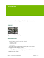
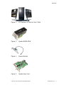
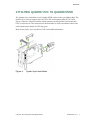
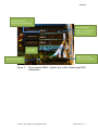
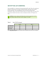
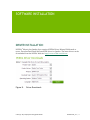
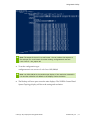
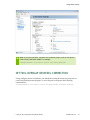
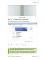
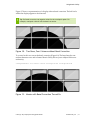
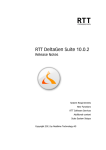
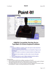
CREATING A 3 BY 3 DISPLAY WALL USING QUADRO MOSAIC DA-06561-001_v01 | October 2012 Application Note DOCUMENT CHANGE HISTORY DA-06561-001_v01 Version Date Authors Description of Change 01 October 18, 2012 VR, SM Initial Release Creating A 3 By 3 Display Wall Using Quadro Mosaic DA-06561-001_v01 | ii TABLE OF CONTENTS Hardware ........................................................................................... 1 Displays ........................................................................................... 1 Workstation ...................................................................................... 1 Attaching Quadro Sync to Quadro K5000 .................................................... 3 Identifying GPU Ordering ...................................................................... 5 Software Installation ............................................................................. 6 Driver Installation ............................................................................... 6 Mosaic Utility .................................................................................... 7 Attaching the Displays to the Quadro K5000 ................................................ 9 Identifying Display Connection Port Numbers ............................................. 10 Understanding Mosaic Display Topologies .................................................. 11 Using Mosaic Utility.............................................................................. 13 Setting Overlap or Bezel Correction......................................................... 15 Configuremosaic Options ....................................................................... 18 Help .............................................................................................. 18 Query ............................................................................................ 18 Test and Set .................................................................................... 21 Grid Options .................................................................................... 23 Disable ........................................................................................... 24 Advanced Options .............................................................................. 25 Frequently Asked Questions ................................................................... 26 Creating A 3 By 3 Display Wall Using Quadro Mosaic DA-06561-001_v01 | iii LIST OF FIGURES Figure 1. Figure 2. Figure 3. Figure 4. Figure 5. Figure 6. Figure 7. Figure 8. Figure 9. Figure 10. Figure 11. Figure 12. Figure 13. Figure 14. Figure 15. Figure 16. Figure 17. Figure 18. Figure 19. Figure 20. 9 Identical Displays................................................................... 1 PCI Express x16 Gen3 or Gen 2 Slots............................................... 2 Quadro K5000 GPUs .................................................................. 2 Stereo Bracket ........................................................................ 2 Quadro Sync Card .................................................................... 2 Quadro Sync Installation ............................................................ 3 Three Quadro K5000 + Quadro Sync in Box Technologies 8950 Workstation . 4 Driver Downloads ..................................................................... 6 Mosaic Utility Download ............................................................. 7 Save Mosaic Utility to an Accessible Folder ...................................... 8 Quadro K5000 Back Plane ........................................................... 9 Workstation Rear Connection ...................................................... 10 Display Connection Port Numbers ................................................. 11 Mosaic 3 by 3 Display Numbers .................................................... 11 3 by 3 Grid Default GPU Connections............................................. 12 Two Channels with 180 Pixel Overlap ............................................ 16 Screen Resolution with Overlap ................................................... 16 Two Rows, Four Columns without Bezel Correction ............................ 17 Mosaic with Bezel Correction Turned On ........................................ 17 Screen Resolution after Setting 1 Row by 4 Columns .......................... 22 LIST OF TABLES Table 1. Dual CPU PCIe Layout ................................................................ 5 Creating A 3 By 3 Display Wall Using Quadro Mosaic DA-06561-001_v01 | iv HARDWARE To create a 3 × 3 visualization display wall the following hardware is required. DISPLAYS Figure 1. 9 Identical Displays WORKSTATION Three PCI Express ×16 Gen3 or Gen2 slots - Figure 2 ● Windows 7 (64-bit) ● Windows 8 (64-bit) ● Linux (64-bit) Three NVIDIA Quadro® K5000 graphics processing units (GPUs) – Figure 3 Stereo bracket (if stereo display) – Figure 4 ● NVIDIA® part number 930-50764-0000-000. Connect to 4-pin header on the Quadro® K5000. Only one is needed per system. Quadro Sync card – Figure 5 Creating A 3 By 3 Display Wall Using Quadro Mosaic DA-06561-001_v01 | 1 Hardware Figure 2. PCI Express x16 Gen3 or Gen 2 Slots Figure 3. Quadro K5000 GPUs Figure 4. Stereo Bracket Figure 5. Quadro Sync Card Creating A 3 By 3 Display Wall Using Quadro Mosaic DA-06561-001_v01 | 2 Hardware ATTACHING QUADRO SYNC TO QUADRO K5000 The Quadro Sync is attached to each Quadro K5000 cards via the sync ribbon cable. The Quadro Sync card can support up to 4 GPUs. The card requires either PCI or SATA power connector. It does not matter which connector on the Quadro Sync board each GPU is connected to. The connectors are bi-directional so it does not matter which side of the Quadro Sync board or GPU they go to. Refer to the Quadro Sync Installation Guide for detailed information. Figure 6. Quadro Sync Installation Creating A 3 By 3 Display Wall Using Quadro Mosaic DA-06561-001_v01 | 3 Hardware PCIe bus order will determine GPU numbering GPU 0 4 pin VESA stereo header – connected to VESA stereo bracket GPU 1 GPU 2 sync cables Quadro Sync card – supports up to 4 GPUs Quadro Sync Power Figure 7. Three Quadro K5000 + Quadro Sync in Box Technologies 8950 Workstation Creating A 3 By 3 Display Wall Using Quadro Mosaic DA-06561-001_v01 | 4 Hardware IDENTIFYING GPU ORDERING The system BIOS of a workstation will enumerate the GPU order. This will vary between different workstations. It is possible to identify the GPU order based on the mother board connections. GPU 0 is generally the lowest PCI Express number on the motherboard. Table 1 shows the PCI Express layout for a modern dual CPU system. The user manual or label in the chassis of most workstations includes a PCI Express slot map. ! CAUTION: On newer chipsets the PCI Express bus is directly integrated on the CPU. Some systems require dual CPUs in order to support 3 or 4 GPUs. Table 1. Dual CPU PCIe Layout CPU 0 CPU 1 PCIe lane order PCIe 2 PCIe 3 PCIe 3 PCIe 2 Physical order Slot 2 Slot 4 Slot 6 Slot 8 GPU number 0 1 3 2 Note: In this 4 GPU example the PCIe order doesn’t follow the physical order of PCIe slots. Slot 8 would enumerate before Slot 6. Creating A 3 By 3 Display Wall Using Quadro Mosaic DA-06561-001_v01 | 5 SOFTWARE INSTALLATION DRIVER INSTALLATION NVIDIA® Mosaic plus Quadro Sync requires NVIDIA Driver Release R310 branch or newer. Download and install the latest ODE driver for Quadro. The latest drivers can be downloaded from the NVIDA Web site: http://www.nvidia.com/drivers. Figure 8. Driver Downloads Creating A 3 By 3 Display Wall Using Quadro Mosaic DA-06561-001_v01 | 6 Software Installation MOSAIC UTILITY Download and install the latest Mosaic utility from the NVIDIA Web site: http://www.nvidia.com/drivers. Note: Download and save the Mosaic utility to the Desktop, disk, or another easily accessible folder. Don’t run the installation as the utility is a command line tool not an installer. Figure 9. Mosaic Utility Download Creating A 3 By 3 Display Wall Using Quadro Mosaic DA-06561-001_v01 | 7 Software Installation Figure 10. Save Mosaic Utility to an Accessible Folder Note: Mosaic Utility is a command line tool. Run via the cmd.exe shell on Windows. Save the utility to a disk. The program is named configuremosaic.exe. Creating A 3 By 3 Display Wall Using Quadro Mosaic DA-06561-001_v01 | 8 ATTACHING THE DISPLAYS TO THE QUADRO K5000 The Quadro K5000 has four display connectors. All four can be connected and operated at one time. The ports the Quadro K5000 will auto-enumerate depending on whether or not a display connector is attached. For example if only Ports A and D are connected these would be identified as Display 0 and 1. If we added a display to Port B then A=0, B=1 and D=2. Note: To connect four DVI displays from one card, use two DisplayPort-to-DVI dongles. Figure 11. Port Connector Type A DVI-I B DisplayPort C DisplayPort D DVI-D Quadro K5000 Back Plane Creating A 3 By 3 Display Wall Using Quadro Mosaic DA-06561-001_v01 | 9 Attaching the Displays to the Quadro K5000 IDENTIFYING DISPLAY CONNECTION PORT NUMBERS Figure 12 shows the rear connection of our workstation. GPU 0 is in PCIe Slot 2 GPU 1 is in PCIe Slot 4 GPU 2 is in PCIe Slot 6 Figure 12. Workstation Rear Connection For a 3 × 3 wall we are going to use Ports A, B and C for the connections. For each port we can describe these in terms of GPU display numbers (Figure 13). Creating A 3 By 3 Display Wall Using Quadro Mosaic DA-06561-001_v01 | 10 Attaching the Displays to the Quadro K5000 Figure 13. Display Connection Port Numbers UNDERSTANDING MOSAIC DISPLAY TOPOLOGIES Mosaic display topologies are defined as grid expressed by rows and columns. Figure 14. Mosaic 3 by 3 Display Numbers Creating A 3 By 3 Display Wall Using Quadro Mosaic DA-06561-001_v01 | 11 Attaching the Displays to the Quadro K5000 For a 3 by 3 configuration the grid is numbered top left to bottom right and going left to right across the rows. We want to connect GPU 0, Port 0 to the top left corner. Each row is being driven by a single GPU. In doing this we will connect the default layout for Mosaic. Figure 15. 3 by 3 Grid Default GPU Connections Note: Use the configuremosaic.exe tool to enable Mosaic. Run it from cmd.exe. Make sure the command shell has Administrator rights. configuremosaic.exe set rows=3 cols=3 Creating A 3 By 3 Display Wall Using Quadro Mosaic DA-06561-001_v01 | 12 USING MOSAIC UTILITY The Mosaic Utility is designed to setup Mosaic from a command line. Refer to “Configuremosaic Option” section for all the options. 1. Open cmd.exe in windows to run the utility. 2. Change to the directory where the configuremosaic.exe file is saved. In this example it is saved on the Desktop. 3. Note: Mosaic is laid out in a grid setting defined by rows and columns. For a nine display set-up we have 3 rows with 3 columns. Each display needs to run the same resolution. Type “configuremosaic test rows=3 cols=3.” This will test if the grid is valid. It will also printout all the valid resolutions that can be supported for Mosaic. Creating A 3 By 3 Display Wall Using Quadro Mosaic DA-06561-001_v01 | 13 Using Mosaic Utility 4. To set the configuration type: configuremosaic.exe set rows=3 cols=3 res=1920,1080,60 5. Note: The output of the tool is on xml format. You can redirect the output to a file and open it in a xml viewer for easier reading. configuremosaic.exe test rows=3 cols=3 > test_report.xml Note: res=1920,1080,60 is the resolution per display. If the resolution command is not used the resolution will default to the displays’ native resolution. The Desktop will now span across the nine displays. The NVIDIA Control Panel System Topology display will show the setting and resolution. Creating A 3 By 3 Display Wall Using Quadro Mosaic DA-06561-001_v01 | 14 Using Mosaic Utility Note: If you use powershell, instead of the command prompt, some of the options need to have parenthesis added. For example: Configuremosaic set rows=3 cols=3 res=”1920,1080,60” SETTING OVERLAP OR BEZEL CORRECTION Using configure mosaic tool Mosaic can match the overlap between two projectors or correct for bezels between displays. To set a 180 pixel overlap use the following command line: configuremosaic set rows=1 cols=2 overlapcol=180 res=1920,1080,60 Creating A 3 By 3 Display Wall Using Quadro Mosaic DA-06561-001_v01 | 15 Using Mosaic Utility Figure 16. Two Channels with 180 Pixel Overlap The total display resolution will now be 3660 (3840-180) pixels. Figure 17. Screen Resolution with Overlap Note: Overlap is not the same as edge-blending. Overlap is setting the desktop to create the overlap region between two projectors. Edge-blending requires intensity roll-off between the projectors. Edge-blending can be done in the GPU using NVIDIA’s Warp and Intensity API. This API is available to developers. Contact [email protected] for more details. Creating A 3 By 3 Display Wall Using Quadro Mosaic DA-06561-001_v01 | 16 Using Mosaic Utility Figure 17 shows a representation of a display without bezel correction. The half circle within the display appears to be distorted. ! Tip: For Bezel correction use negative values for the overlapcol option. For example, overlapcol=-180 will set the bezel correction. Figure 18. Two Rows, Four Columns without Bezel Correction To correct for this we can set the bezel correction (Figure 18). The bezel may be nonuniform between rows and columns. Mosaic Utility allows you to adjust for this non uniformity. configuremosaic set rows=2 cols=4 overlapcol=-50 overlaprow=-100 Figure 19. Mosaic with Bezel Correction Turned On Creating A 3 By 3 Display Wall Using Quadro Mosaic DA-06561-001_v01 | 17 CONFIGUREMOSAIC OPTIONS Usage: configuremosaic <command> [arguments] Command options: help, query, test, set, disable. HELP Prints out help file all the options. Usage: configuremosaic.exe help Tip: Use “configuremosaic help” to printout the latest options. ! QUERY Returns information on the current system or configuration. Usage: configuremosaic query [query command] [query command] = ● gpu – display the list of physical GPUs and attached displays ● lgpu – display the list of possible logical GPUs ● current – display the current display grid ● all – display all the above information Creating A 3 By 3 Display Wall Using Quadro Mosaic DA-06561-001_v01 | 18 Configuremosaic Options Example: 4 GPUs in one system configuremosaic query gpu <?xml version="1.0"?> <query version="1.2.4"> <physicalgpus> <physgpu gpuid="0x000200"> <name>Quadro K5000</name> <displays> <display displayid="0x80061082" outputid="0x010000" <shortname>DFP0</shortname> <name>Dell Alienware2310</name> </display> </displays> </physgpu> <physgpu gpuid="0x000300"> <name>Quadro K5000</name> <displays> <display displayid="0x80071082" outputid="0x010000" <shortname>DFP0</shortname> <name>Dell Alienware2310</name> </display> </displays> </physgpu> <physgpu gpuid="0x008400"> <name>Quadro K5000</name> <displays> <display displayid="0x80041082" outputid="0x010000" <shortname>DFP0</shortname> <name>Dell Alienware2310</name> </display> </displays> </physgpu> <physgpu gpuid="0x008500"> <name>Quadro K5000</name> <displays> <display displayid="0x80051082" outputid="0x010000" <shortname>DFP0</shortname> <name>Dell Alienware2310</name> </display> </displays> </physgpu> </physicalgpus> </query> Creating A 3 By 3 Display Wall Using Quadro Mosaic type="dfp"> type="dfp"> type="dfp"> type="dfp"> DA-06561-001_v01 | 19 Configuremosaic Options Example: Single display attached configuremosaic query current <?xml version="1.0"?> <query version="1.2.4"> <grids> <grid rows="1" columns="1"> <displaymode width="1920" height="1080" bpp="32" freq="120" /> <position x="0" y="0" /> <displays> <display displayid="0x80051082" overlapcolumn="0" overlaprow="0" rotation="0" /> </displays> </grid> </grids> </query> Creating A 3 By 3 Display Wall Using Quadro Mosaic DA-06561-001_v01 | 20 Configuremosaic Options TEST AND SET Set or test one or more display grids. Use the token “nextgrid” to separate multiple grids. If successful the command will return “valid=1” at the top of the xml output. Usage: configuremosaic <test|set> <grid options> [nextgrid <grid options>]…. Example: Test if rows=1 and cols=2 is valid and print out the valid resolutions. configuremosaic test rows=1 cols=2 <?xml version="1.0"?> <test version="1.2.4" valid="1"> <grids> <grid rows="1" columns="2"> <displaymode width="1920" height="1080" bpp="32" freq="120" /> <displays> <display displayid="0x80061082" overlapcolumn="0" overlaprow="0" rotation="0" /> <display displayid="0x80071082" overlapcolumn="0" overlaprow="0" rotation="0" /> </displays> <gridstatus> <gridflags> <warningflags flags="0x02"> <flag>DRIVER_WILL_BE_RELOADED</flag> </warningflags> </gridflags> <displayflags displayid="0x80061082" /> <displayflags displayid="0x80071082" /> </gridstatus> <displaymodelist> <displaymode width="1680" <displaymode width="1680" <displaymode width="1680" <displaymode width="1680" <displaymode width="1920" <displaymode width="1920" <displaymode width="1920" <displaymode width="1920" </displaymodelist> </grid> </grids> </test> ! height="1050" height="1050" height="1050" height="1050" height="1080" height="1080" height="1080" height="1080" bpp="32" bpp="32" bpp="32" bpp="32" bpp="32" bpp="32" bpp="32" bpp="32" freq="60" /> freq="100" /> freq="110" /> freq="120" /> freq="60" /> freq="100" /> freq="110" /> freq="120" /> Tip: Common error with Mosaic is that not all the displays support the same display resolution. The test option will print out the list of all the valid resolutions for a given setup. If you use Configuremosaic.exe test rows=1 cols=2 > my_test_file.xml The output from test will saved in an xml file for easier reading. Creating A 3 By 3 Display Wall Using Quadro Mosaic DA-06561-001_v01 | 21 Configuremosaic Options Example – Set rows=1 cols=4 configuremosaic set rows=1 cols=4 <?xml version="1.0"?> <set version="1.2.4" valid="1"> <grids> <grid rows="1" columns="4"> <displaymode width="1920" height="1080" bpp="32" freq="60" /> <displays> <display displayid="0x80061082" overlapcolumn="0" overlaprow="0" rotation="0" /> <display displayid="0x80071082" overlapcolumn="0" overlaprow="0" rotation="0" /> <display displayid="0x80041082" overlapcolumn="0" overlaprow="0" rotation="0" /> <display displayid="0x80051082" overlapcolumn="0" overlaprow="0" rotation="0" /> </displays> <gridstatus> <gridflags /> <displayflags displayid="0x80061082" /> <displayflags displayid="0x80071082" /> <displayflags displayid="0x80041082" /> <displayflags displayid="0x80051082" /> </gridstatus> </grid> </grids> </set> This results in one large desktop as shown by Screen Resolution properties. Figure 20. Screen Resolution after Setting 1 Row by 4 Columns Creating A 3 By 3 Display Wall Using Quadro Mosaic DA-06561-001_v01 | 22 Configuremosaic Options GRID OPTIONS rows = the number of rows in the grid cols = the number of columns in the grid passivestereo = enables passive stereo out=GPU_id, display_id – specifies the output order. i.e to flip the display order from: to: Use: configuremosaic set rows=1 cols=2 out=0,1 out=0,0 The GPU_id and out_id are explained earlier in this application note overlap=COL, ROW – specifies the overlap for the entire grid overlapcol= specifies overlap between columns - col1,col2, col3,… For example, configuremosaic set rows=2 cols=4 overlapcol=0,180,0 overlaprow= specifies overlap between rows - row1,row2, row3,… rotate – specifies a rotation value for displays in a grid. Creating A 3 By 3 Display Wall Using Quadro Mosaic DA-06561-001_v01 | 23 Configuremosaic Options To configure each display in Portrait mode: configuremosaic set rows=1 cols=4 rotate=90 ! Tip: Do not set displays into portrait mode and then try and configure Mosaic, as this is not supported. Use the rotate option to rotate the displays in the grid. DISABLE Disable sets Mosaic to a 1 × 1 grid layout. Usage: configuremosaic disable ! Tip: configuremosaic set rows=1 cols=1 has the same effect as disable. You can specify which display in the grid becomes active by using the out option. For example: configuremosaic set rows=1 cols=1 out=0,0 configuremosaic set rows=1 cols=1 out=1,0 Creating A 3 By 3 Display Wall Using Quadro Mosaic DA-06561-001_v01 | 24 Configuremosaic Options ADVANCED OPTIONS dohiccluster <master|slave|non-cluster> This is related to using dual QuadroPlex 7000 as part of a display cluster. Contact [email protected] for more details on this type of advanced setup. Creating A 3 By 3 Display Wall Using Quadro Mosaic DA-06561-001_v01 | 25 FREQUENTLY ASKED QUESTIONS Q: I have a question about NVIDIA’s SVS products. Who should I contact? A: Email: [email protected] Q: What OS is supported for Mosaic? A: Windows XP, Windows 7, Windows 8 and Linux. Q: What is the maximum of displays you can support with Mosaic? A: We support up to 16 display outputs with the Quadro K5000 cards (8 display outputs on Windows XP and older versions of Quadro GPUs). For larger arrays, contact [email protected] for solution options. Q: What workstations can support three or four Quadro K5000 cards? A: It is best to contact the workstation manufacturers to confirm that their system can support three or four GPUs, not only from a mechanical and electrical viewpoint but also to ensure that the system BIOS can correctly detect the GPUs and assign all necessary resources. Creating A 3 By 3 Display Wall Using Quadro Mosaic DA-06561-001_v01 | 26 Frequently Asked Questions Q: Is a Quadro Sync card always required? A: A Quadro Sync card should be used to enable Premium Mosaic which will ensure “tear free” image on the display. Premium Mosaic is required for: Overlap correction Warp plus blend functions Stereoscopic 3D We recommend using the Quadro Sync with the Quadro K5000 when using projection displays and displays that have ultra-thin bezels. A Quadro Sync card is not required for Premium MOSAIC between two Quadro K5000s in a Quadro SLI Compatible Systems http://www.nvidia.com/object/quadro_sli_compatible_systems.html Q: Do all my displays need to be identical? A: Yes. All the displays need to run the same resolution, refresh and backend timing for Mosaic. Q: What is the maximum resolution that Mosaic can support? A: The total horizontal or vertical resolution of the display cannot exceed 16 k pixels. Q: Is Mosaic compatible with video wall controllers and splitters? A: Yes. We have customers who use video splitters to increase the number of displays beyond 16. Contact [email protected] for more details. Q: Can I mix DisplayPort and DVI connections? A: Yes, as long as all the displays use the same input type (all DVI in this case). You will need to use either a passive or active (powered) dongle depending on the display resolution you require. Passive dongles support up to single-link DVI bandwidth (165 MHz) which is approximately 1920 × 1200 at 60 Hz resolution. Most active dongles support up to 2560 × 1600 at 60 Hz (270 MHz) resolution. Creating A 3 By 3 Display Wall Using Quadro Mosaic DA-06561-001_v01 | 27 Frequently Asked Questions NVIDIA certified active dongles support up to 1920 × 1200 at 120 Hz (330 MHz) resolution (NVIDIA part number: 030-0378-000 and Bizlink part number: KS10014-B07). Q: My displays have HDMI connections. How do I connect to these? A: Use a DVI-to-HDMI and/or DisplayPort-to-HDMI dongle or cable. The Quadro cards support native HDMI. When the driver detects an HDMI display it switches to HDMI signaling over the DVI or DisplayPort ports. Q: Can Mosaic be used with cable and fiber extenders, and/or video switchers? A: Yes. Some device extenders or switchers may not report the EDID correctly from the display device. We recommend that you use the Manage EDID function built into the display driver to capture the EDID from the display device and save to file. You can assign the EDID from the file to graphics output. Q: What grid layouts do you support with Mosaic? A: Number of Displays Supported Topologies (Rows x Columns) 2 1x2 2x1 3 1x3 3x1 4 1x4 2x2 5 1x5 5x1 6 1x6 2x3 7 1x7 7x1 8 1x8 9 4x1 3x2 6x1 2x4 4x2 8x1 1x9 3x3 9x1 10 1 x 10 2x5 5x2 10 x 1 11 1 x 11 11 x 1 12 12 x 1 2x6 3x4 4x3 13 1 x 13 13 x 1 14 1 x 14 2x7 7x2 14 x 1 15 1 x 15 3x5 5x3 15 x 1 16 1 x 16 2x8 4x4 8x2 6x2 1 x 12 16 x 1 Note: The maximum horizontal or vertical resolution cannot exceed 16 k pixels. Some topologies will only work at lower resolution per screen. Creating A 3 By 3 Display Wall Using Quadro Mosaic DA-06561-001_v01 | 28 Notice ALL NVIDIA DESIGN SPECIFICATIONS, REFERENCE BOARDS, FILES, DRAWINGS, DIAGNOSTICS, LISTS, AND OTHER DOCUMENTS (TOGETHER AND SEPARATELY, “MATERIALS”) ARE BEING PROVIDED “AS IS.” NVIDIA MAKES NO WARRANTIES, EXPRESSED, IMPLIED, STATUTORY, OR OTHERWISE WITH RESPECT TO THE MATERIALS, AND EXPRESSLY DISCLAIMS ALL IMPLIED WARRANTIES OF NONINFRINGEMENT, MERCHANTABILITY, AND FITNESS FOR A PARTICULAR PURPOSE. Information furnished is believed to be accurate and reliable. However, NVIDIA Corporation assumes no responsibility for the consequences of use of such information or for any infringement of patents or other rights of third parties that may result from its use. No license is granted by implication of otherwise under any patent rights of NVIDIA Corporation. Specifications mentioned in this publication are subject to change without notice. This publication supersedes and replaces all other information previously supplied. NVIDIA Corporation products are not authorized as critical components in life support devices or systems without express written approval of NVIDIA Corporation. HDMI HDMI, the HDMI logo, and High-Definition Multimedia Interface are trademarks or registered trademarks of HDMI Licensing LLC. Trademarks NVIDIA, the NVIDIA logo, and Quadro are trademarks and/or registered trademarks of NVIDIA Corporation in the U.S. and other countries. Other company and product names may be trademarks of the respective companies with which they are associated. Copyright © 2012 NVIDIA Corporation. All rights reserved. www.nvidia.com