1
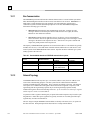
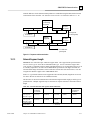
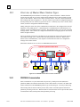
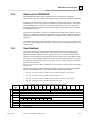
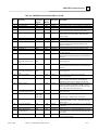
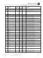
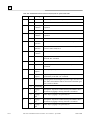
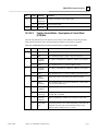
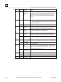
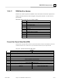
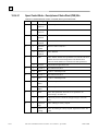
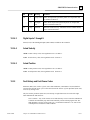
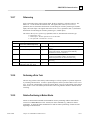
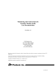
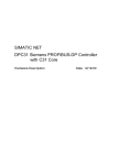
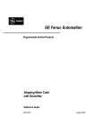
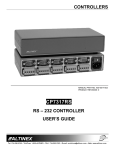
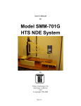
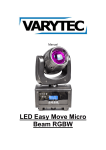
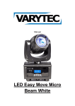
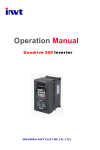
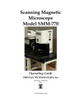
Chapter
PROFIBUS Communications
10
10.1
PROFIBUS Network Overview
PROFIBUS is an open, vendor-independent fieldbus standard for a wide range of
applications in industrial automation, including motion control.
PROFIBUS is a dynamic technology that grows functionally while complying with
the European Fieldbus Standard EN 50 170.
PROFIBUS Guidelines and Profiles provide the means for further technical
development based on the ever-changing communication requirements of the
networks, systems, and devices used in today's industrial automation applications.
PROFIBUS specifications reference three different protocols to cover a range of industrial
requirements:
PROFIBUS – DP
High speed data communication. DP stands for Decentralized
Periphery. In practice, the majority of slave applications are DP
applications. The GE Fanuc S2K Motion Controller is a
PROFIBUS-DP Slave device.
PROFIBUS – FMS
Object oriented general-purpose data communication. FMS
stands for Fieldbus Message Specification. FMS protocol
devices may exchange data on the same bus used for DP
devices.
PROFIBUS – PA
Meets requirements for intrinsical safety and non-intrinsical
safety areas and includes bus-powered field devices.
The PROFIBUS logo is a trademark of the PROFIBUS International Organization. Membership in
the organization is open to all individuals, companies and organizations. More information about the
organization and the protocol is available at http://www.profibus.com
GFK-1848B
10-1
10
10.1.1
Bus Communication
The PROFIBUS specification defines the technical characteristics of a serial field bus system that
links distributed digital controllers on the network, from field level to cell level. PROFIBUS is a
multi-master system that allows the joint operation of several automation, engineering or
visualization systems with their distributed peripherals on one bus. PROFIBUS distinguishes
between the following types of devices:
•=
Master devices determine the data communication on the bus. A master can send
messages without an external request when it holds the bus access rights (the token).
Masters are also called active stations.
•=
Slave devices include motion controllers, drives, I/O devices, valves, and transducers.
Slaves do not have bus access rights and can only acknowledge received messages or send
messages to the master when requested to do so. Slave devices are passive stations and
require only small portions of the bus protocol.
The majority of PROFIBUS-DP applications are located at the field level. The field level typically
includes slave devices (i.e. the S2K motion controller station) and host devices such as PLC or PC
control systems for the PROFIBUS-DP master station. Operator interfaces and DCS type systems
usually operate at the cell level.
Table 10-1. Data bandwidth demands on PROFIBUS communications systems
10.1.2
Level
Amount of Data
Management level
Cell level
Field Level
Mbytes
Kbytes
Bytes
Actuator sensor level
Bits
Transmission
Duration
Hours/Minutes
Seconds
Several 100 µseconds
to 100 milliseconds
µsec to milliseconds
Transmission
Frequency
Day/Shift
Hours/Minutes
10 to 100 milliseconds
Milliseconds
Network Topology
A PROFIBUS-DP network may have up to 127 stations (address 0-126), however address 126 is
reserved for commissioning purposes. The bus system must be sub-divided into individual
segments to handle this many participants. These segments are linked by repeaters. The function
of a repeater is to condition the serial signal to allow connection of segments. In practice, both
regenerating and non-regenerating repeaters may be used. Regenerating repeaters actually
condition the signal to allow increased range of the bus. Up to 32 stations are allowed per segment
and the repeater counts as a station address.
A specialized “link” segment consisting only of optical fiber modem repeaters may be used to span
long distances. Plastic fiber optic segments are typically 50 meters or less while glass fiber optic
segments may extend several kilometers.
The user assigns a unique PROFIBUS station address to identify each master, slave, or repeater in
the entire network. Each participant on the bus must have a unique station address.
10-2
S2K Series Standalone Motion Controller User's Manual – April 2002
GFK-1848B
PROFIBUS Communications
10
Network addresses for the GE Fanuc S2K products are established using the DIP switches located
on the bottom of the controller. The GE Fanuc S2K controllers accommodate addresses 0 – 99.
Repeater
Connecting
Segments
Participant
Participant
Participant
Remote
Repeater
Link Segment
(No Participants)
Termination
Branch
Segment
Participant
Participant
Participant
Remote
Repeater
Termination
To additional
participants
Figure 10-1. Repeaters and bus termination
10.1.3
Network Segment Length
PROFIBUS uses either fiber optic or RS-485 copper media. The copper bus line specified in EN
50 170 is “Line Type A” and is the recommended cable type. A more economical copper cable
“Line Type B” is commonly used for smaller installations however is not specified in EN 50 170. It
is extremely important to use cable rated to PROFIBUS specifications. The higher the baud rate
selected and the longer the distances involved the more critical cable selection becomes. You will
recognize the distinctive purple color of PROFIBUS cable.
Stub or “T” type branch connections are supported if the total stub (branch) lengths do not exceed
6.6 meters. Do not use stubs at all on 12 Mbaud networks.
The data rates for network communication with maximum segment trunk length per cable type are
provided below. Multiple segments may be connected via repeater stations to extend the total bus
length.
Table 10-2. Network Data Rates and segment distance limitations
Data Rates
9600 baud
187.5 Kbaud
500 Kbaud
19.2 Kbaud
93.75 Kbaud
Trunk distance: 1.2 km
1,000 m
400 m
Line Type A
(~3,937 ft)
(~3,280 ft)
(~1,312 ft)
RS-485 Copper
Trunk distance: 1.2 km
600 m
200 m
Line Type B
(~3,937 ft)
(~1,968 ft)
(~656 ft)
RS-485 Copper
Trunk Distance:
@ 6 km
(glass) Fiber
(~19,685 ft)
GFK-1848B
Chapter 10 PROFIBUS Communications
1,500 Kbaud
200 m
(~656 ft)
3,000 Kbaud
6,000 Kbaud
12 Mbaud
100 m
(~328 ft)
N/A
N/A
10-3
10
10.1.4
Network connectors
PROFIBUS connections are created with a 9 pin sub-D connector. A minimum connection is to
use a shielded pair of wires (Pins 1, 3 and 8) with terminating connections in the appropriate bus
plugs. The pin to signal conventions are described below.
Table 10-2. Plug Connector Pin Allocation of the PROFIBUS Bus Plug Connector
10.1.5
Pin No.
Signal
Designation
1
Shield
Shield / Protective Ground
2
M24
Ground / Common of the 24 V output voltage
3
RxD/TxD-P
Receive data / transmission data plus
4
CNTR-P
Control signal for repeaters (direction control)
5
DGND
Data transmission potential (ground to 5V)
6
VP
Supply voltage of the terminating resistance (+ 5 V)
7
P24
Output voltage (+ 24 V)
8
RxD/TxD-N
Receive data / transmission data negative
9
CNTR-N
Control signal for repeaters (direction control)
Network Termination
The bus must be terminated at both ends of the trunk line. Commercially available plug connectors
may have built in terminating resistors or you may build your own.
Pin 6
390 ohm
Pin 3
220 ohm
Pin 8
390 ohm
Pin 5
Pin 1
Figure 10-2. Bus Termination for Type A cable in accordance to PROFIBUS specifications
10-4
S2K Series Standalone Motion Controller User's Manual – April 2002
GFK-1848B
PROFIBUS Communications
10.1.6
10
Network Baud Rate
The master configures the appropriate network baud for each station on the network. Allowed
values for S2K network baud rates are: 9,600; 19,200; 45,450; 93,750; 187,500; 500,000;
1,500,000; 3,000,000; 6,000,000; or 12,000,000.
GFK-1848B
Chapter 10 PROFIBUS Communications
10-5
10
10.2
Getting Started
The following information is intended to outline the steps required to commission a S2K and
incorporate it into a PROFIBUS network segment.
10.2.1
Connection Checklist
GE Fanuc-Supplied Components
1 S2K controller with PROFIBUS per axis
1 motor per axis
Cables
CIMPLICITY Motion Developer software
User-Supplied Components
DC power to digital I/O
16-gauge wire to jumper I/O connectors
PROFIBUS network hardware
10.2.2
Complete Basic Set-up Procedure
Before you connect and use your S2K controller on PROFIBUS, take a few minutes to complete
the Process for Basic Set-up located in Chapter 4:
The set-up process takes you systematically through each of the following items:
•
Install software
•
Connect cables
•
Jumper dedicated I/O (if applicable)
•
Establish communication with the controller
•
Complete basic equipment configuration
•
Run the motor to verify correct set-up.
If you are using multiple S2K controllers, repeat the set-up for each controller. When you have
completed the set-up, leave your connections and jumpers in place—you’re ready to configure your
PROFIBUS system.
To operate S2K Controllers for PROFIBUS, the S2K controller requires some simple network
configuration before being used.
10-6
S2K Series Standalone Motion Controller User's Manual – April 2002
GFK-1848B
PROFIBUS Communications
10
Step 1: Set the PROFIBUS
Address
The PROFIBUS address provides a unique
network address, from 0 through 99, for each
S2K node. S2K controllers ship from the
factory with the PROFIBUS address set to one.
Caution: Ensure that controller power is off
before you handle DIP switches.
Use the DIP switches located on the bottom of
the controller to set the PROFIBUS address to a
network address indicated in figure 10-4.
Figure 10-3 shows the location of the controller
switches and the proper orientation for left and
right switch settings.
Figure 10-4. Location of DIP Switches on Bottom
of S2K Controller
GFK-1848B
Chapter 10 PROFIBUS Communications
Figure 10-3. S2K DIP Switch Profibus Address
Settings
10-7
10
Step 2: Configure Master to Add Slave to the Network
PROFIBUS-DP systems accept S2K controllers as slaves to a network master. The network master
automatically sets the network data rate for the S2K controllers that have been properly configured
and connected to the network.
A device electronic data sheet or GSD file for the S2K Motion Controller is available from GE
Fanuc to expedite the master configuration. A GSD file contains information to specify methods of
communication and types of messaging available. Most PROFIBUS master configuration tools
require the GSD file in order to operate.
10.2.3
The GSD File Data for the S2K Motion Controller
;======================================================
; GSD File Standalone Motion Controller
;
; Version: V1.0
;======================================================
#Profibus_DP
GSD_Revision
=1
;General parameters
Vendor_Name
= "Whedco, Inc."
Model_Name
= "Standalone Motion Controller"
Revision
= "V1.0"
Ident_Number
= 0x05E9
Protocol_Ident
=0
Station_Type
=0
FMS_supp
=0
Hardware_Release = "D"
Software_Release = "V1.0"
9.6_supp
=1
19.2_supp
=1
45.45_supp
=1
93.75_supp
=1
187.5_supp
=1
500_supp
=1
1.5M_supp
=1
3M_supp
=1
6M_supp
=1
12M_supp
=1
MaxTsdr_9.6
= 60
MaxTsdr_19.2
= 60
MaxTsdr_45.45
= 250
MaxTsdr_93.75
= 60
MaxTsdr_187.5
= 60
MaxTsdr_500
= 100
MaxTsdr_1.5M
= 150
MaxTsdr_3M
= 250
MaxTsdr_6M
= 450
MaxTsdr_12M
= 800
Redundancy
=0
10-8
S2K Series Standalone Motion Controller User's Manual – April 2002
GFK-1848B
PROFIBUS Communications
10
Repeater_Ctrl_Sig = 2
24V_Pins
=0
Implementation_Type = "DPC31"
; Slave-Specification:
Freeze_Mode_supp = 1
Sync_Mode_supp
=1
Auto_Baud_supp
=1
Set_Slave_Add_Supp = 0
User_Prm_Data_Len = 3
; 3 bytes for DPV1
User_Prm_Data
= 0x00,0x00,0x00
Fail_Safe
=1
Min_Slave_Intervall = 1
Max_Diag_Data_Len = 6
Modul_Offset
=0
Slave_Family
=1
; Drive Family
Modular_Station
=1
Max_Module
= 1 ; Only one module at a time
Max_Input_Len
= 20 ; 20 bytes input data
Max_Output_Len
= 20 ; + 20 bytes output data
Max_Data_Len
= 40 ; = 40 bytes I/O data
; Module Definition List
;
; PPO Type 1 (PKW 4 words, PZD 2 words)
;
Module = "PPO-Type 1" 0xF3, 0xF1
EndModule
;
; PPO Type 2 (PKW 4 words, PZD 6 words)
;
Module = "PPO-Type 2" 0xF3, 0xF5
EndModule
;
; PPO Type 3 (PZD 2 words)
;
Module = "PPO-Type 3" 0xF1
EndModule
;
; PPO Type 4 (PZD 6 words)
;
Module = "PPO-Type 4" 0xF5
EndModule
GFK-1848B
Chapter 10 PROFIBUS Communications
10-9
10
10.3
Overview of Master/Slave Station Types
The PROFIBUS-DP protocol defines two station types: Masters and Slaves. Masters form the
logical token ring and may access the medium while holding the token. Masters initiate message
cycles to other stations. There are two classes of master devices. The class 1 master handles the
data exchange with slaves assigned to it. The class 2 master is provided for configuration purposes
and may briefly take over control of a given slave device. Commonly only a class 1 master (mono
master) is used for configuration and data messaging.
During startup, the master sets up the communication connections to the configured slave list and
begins the cyclic polling process. A monitoring time is established and if communication is not
possible, an error in communications is reported. This monitoring time is reset on each successful
message transfer. Slave stations are configured and added to the messaging sequence from lowest
address to highest address.
Slaves act neutrally with respect to medium access and respond to requests from master stations
only within a message cycle. All slaves have the same priority for bus access. When a slave
detects a loss of communication, it sets outputs to a known state and waits for a configuration
message from a master station.
S2K motion controllers serve as slaves on a PROFIBUS-DP network.
logical token ring between the master stations
PLC
PLC
Masters
Active
stations
PROFIBUS
Up to 125
Slaves...
Passive
stations
Sensor
Sensor
Sensor
Actuator
T
Transmitter
Figure 10-5. PROFIBUS Master/Slave Network Architecture
10.3.1
PROFIBUS Communication
S2K’s communicate via cyclic data transfer, the process by which process data (PZD) and
parameters (PKW) are transferred from master to slave and from slave to master. GE Fanuc S2K
motion controllers use the PROFIBUS profile's Type 2 Octet-String 20 -- the 20-byte data string.
When writing data, the master transfers process data (control word and setpoints) and tasks for
parameter processing to the slave. When the data are read, the master retrieves process data (status
word and actual values) and responses from parameter processing.
10-10
S2K Series Standalone Motion Controller User's Manual – April 2002
GFK-1848B
PROFIBUS Communications
10.3.2
10
Global Control for PROFIBUS-DP
The PROFIBUS-DP "global control" mechanism can be used when slave coordination
requirements are high. For example, when setpoints must be switched or specified simultaneously.
In addition to the node-related user data communication, the masters can send control commands
simultaneously to one slave, a group of slaves (Multicast) or all slaves (Broadcast). These global
control commands can be used for event-controlled synchronization of the slaves. The master
establishes the global commands to use and assigns the global group number to the slaves during
the configuration message.
Typical global commands are “clear data” to establish a known output state on fault, the “freeze”
message to coordinate the reading of the inputs and the “sync” message to coordinate switching of
outputs. There is additionally an unfreeze and unsync command to restore the station to normal
messaging.
The S2K Motion Controller supports global messages: clear data, auto baud, freeze/unfreeze and
sync/unsync. The global message change address is not supported. The S2K station address is set
via DIP switches.
10.3.3
Output Data Words
Output
Word
1
2
3
4
5
6
PZD
PKW
The format for the 20 bytes of data the PROFIBUS-DP master will write to the S2K motion
controller is described in the following table. This format conforms to the user profile group
PROFIDrive 0302hex (indicates Version 2, Application Class 3). User profile groups promote
operability between products created by different vendors and allow users to interchange products.
The Parameter Channel (PKW), composed of the first four data words (eight bytes), is used with
the appropriate Task ID and Parameter Number (PNU) to access variable and register data in the
S2K on an as needed basis.
The Process Data Channel (PZD), composed of two to six words, is used to operate the axis and is
always active.
The message (telegram) actually transmitted to the S2K will take one of the following supported
message forms depending on the settings in the Task ID and Control Word (STW):
GFK-1848B
Bit
15
Res
7
8
9
10
•
PPO-Type 1 message consisting of 4 PKW words and 2 PZD words (PZD – words 5 and 6).
•
PPO-Type 2 message consisting of 4 PKW words and 6 PZD words.
•
PPO-Type 3 message consisting of 0 PKW words and 2 PZD words (PZD – words 5 and 6).
•
PPO-Type 4 message consisting of 0 PKW words and 6 PZD words.
Table 10-4. PROFIBUS-DP Output Data Words for S2K Motion Controllers
Bit
Bit
Bit
Bit
Bit
Bit
Bit
Bit
Bit
Bit
Bit
Bit
14
13
12
11
10
9
8
7
6
5
4
3
Task ID
Res
Parameter Number (PNU)
Index
Reserved
Parameter Value MSW
Parameter Value LSW
Control Word (STW)
Digital Outputs
Motion Block to Execute
Res
14
13
12
11
10
9
Velocity Setpoint MSW
Velocity Setpoint LSW
Position Setpoint MSW
Position Setpoint LSW
Res = Reserved
Chapter 10 PROFIBUS Communications
Bit
2
Bit
1
Bit
0
10-11
10
10.3.3.1
Parameter Channel Task ID
The Task ID defines the functions available in the parameter channel (PKW) and sets behavior for
the PKW messaging. Setting Task ID equal to zero effectively shuts down the parameter channel
and causes the remainder of the channel to be void.
Table 10-3. Available Output Word Task ID’s
Task ID
0
1
2
3
4
5
6
7
8
9
10 – 15
10.3.3.2
Function
No task
Request parameter value
Change parameter value (word)
Change parameter value (double word)
Reserved
Reserved
Request parameter value (array)
Change parameter value (array word)
Change parameter value (array double word)
Request number of array elements
Reserved
Parameter Number (PNU):
The Parameter Number (PNU) allows you to read and write specific registers and variables of the
S2K controller. PROFIBUS-DP parameters fit into two data classes: cyclic and acyclic.
Cyclic data communicate set points and actual values for parameters that frequently change, such
as speed, and position. Cyclic data is contained in the process data channel (PZD). Cyclic
parameters use low quantities of data (from 16 to 32 bits) and require a short cycle time of a few
milliseconds. Cyclic data exchange is efficient and has the following characteristics:
•=
•=
•=
Devices produce data at a user-configured rate
Devices that need more bandwidth can get it
Data are sampled at precise intervals for better determinism
Acyclic data are those parameters that seldom change, like minimum and maximum speed limits.
Acyclic data is transferred over the parameter channel (PKW). Parameters that require higher
quantities of data use acyclic data exchange.
10-12
S2K Series Standalone Motion Controller User's Manual – April 2002
GFK-1848B
PROFIBUS Communications
10
Table 10-4. PROFIBUS Parameter Number (PNU) List for S2K
1
2
3
4
Command Position
Actual Position
Actual Velocity
Following Error
S2K
Equivalent
Register
PSC
PSA
VLA
FE
5
Current Command
6 – 19
20
21
PNU
Parameter
Valid
Access
Modes
Data Type Description
RO
RW
RO
RO
integer32
integer32
integer32
integer16
CMD
RO
integer16
Reserved
Position Setpoint
Velocity Setpoint
MPA/MPI
MVL
RW
RW
integer32
integer32
22
23
24
Acceleration
Deceleration
Jerk
MAC
MDC
MJK
RW
RW
RW
unsigned32
unsigned32
unsigned16
25
Jog Velocity One
MVL
RW
integer32
26
Jog
Acceleration/Deceleration
One
Jog Velocity Two
MAC,
MDC
RW
unsigned32
MVL
RW
integer32
MAC,
MDC
RW
unsigned32
RW
integer32
27
29
Jog
Acceleration/Deceleration
Two
Reference Position
30
Reference Velocity
RW
integer32
31
Marker Velocity
RW
integer16
32
RW
unsigned32
33
Reference
Acceleration/Deceleration
Reference Position Type
RW
unsigned16
34
Torque Limit
RMF, RMR,
RHF, RHR,
ROF, ROR
TLC
RW
unsigned16
35
Torque Limit Enable
TLE
RW
Boolean
36 - 49
50
Reserved
Motor Direction for
Forward moves
DIR
RW
unsigned16
Position Length
PLA
RW
unsigned32
28
51
GFK-1848B
Chapter 10 PROFIBUS Communications
Command position of the axis.
Real position in pulses. Set to redefine actual position.
Actual velocity in pulses/sec.
Axis following error is the difference between the axis
position (PSA) and the command position (PSC).
Position controller command output, used to control the
position of the axis (where 1000 = full continuous
current setting).
Profile move position defined in pulses.
Defines motion velocity of the axis. Signed quantity in
speed control mode automatically determines the
direction of the move.
Profile acceleration rate defined in pulses/second2.
Profile deceleration rate defined in pulses/second2.
Percentage of acceleration/deceleration time that the
axis will jerk limit.
Defines motion velocity of the axis while jogging one.
Signed quantity automatically determines the direction
of the jog.
Defines acceleration/deceleration rate in pulses/second2
while jogging one.
Defines motion velocity of the axis while jogging two.
Signed quantity automatically determines the direction
of the jog.
Defines acceleration/deceleration rate in pulses/second2
while jogging two.
Set actual position (PSA) to this value when
Referencing finishes.
Set velocity (MVL) to this value during Referencing
while in position control mode. Signed quantity
automatically determines the direction of the move.
Defines the motion velocity (MVM) of the axis when
running to a marker input (RMF or RMR). Signed
quantity automatically determines the direction of the
move. Maximum value 4096 pulses/sec.
Defines acceleration/deceleration rate in pulses/sec2
while referencing.
Establishes the type of homing move to execute. Home
to:
0=Home input, 1=Marker input, 2=OT input
Output torque limit; set value to limit torque when
torque limit is enabled. 1000 = 100% full continuous
current setting.
Set to FFhex to enable torque limit; set to 0 to disable
torque limit.
Defines direction: 0=CW forward direction, 1=CCW
forward direction, as viewed from the load end of the
motor shaft.
Defines axis position length (value is half the axis
position register length).
10-13
10
52
Position Wrap Enable
S2K
Equivalent
Register
PWE
53
Overtravel Input Enable
54
56
Forward Software
Overtravel
Reverse Software
Overtravel
Following Error Bound
57
PNU
Valid
Access
Modes
Data Type Description
RW
Boolean
OTE
RW
Boolean
OTF
RW
integer32
OTR
RW
integer32
FEB
RW
unsigned16
In-position Band
IPB
RW
unsigned16
58
Motor Feedback
Resolution
FR
RW
unsigned32
59
Commutation Ratio
CMR
RW
unsigned16
60
Commutation Offset
CMO
RW
integer16
61
Continuous Current
CURC
RW
unsigned16
62
Peak Current
CURP
RW
unsigned16
63
Power Save Current
CURS
RW
unsigned16
64
Proportional Gain
KP
RW
unsigned16
65
Integral Gain
KI
RW
unsigned16
66
Derivative Gain
KD
RW
unsigned16
67
Acceleration Feed Forward KA
RW
unsigned16
68
Filter Time Constant
KT
RW
unsigned16
69
Motor Inductance
KL
RW
unsigned16
55
10-14
Parameter
Determines whether position register wrap is enabled:
FFhex = enabled; 0 = disabled.
Determines whether hardware overtravel inputs are
enabled:
FFhex = enabled; 0 = disable.
Defines forward software overtravel limit for the axis in
pulses.
Defines reverse software overtravel limit for the axis in
pulses.
Limit set on the following error in pulses. System faults
when limit is exceeded.
Defines maximum amount of position error in pulses
that the axis can have and still be in position.
Number of actual position feedback pulses in one
revolution of the motor. Set value to a positive number
only.
Motor poles to resolver poles commutation ratio. One
of the motor constants needed to operate a resolver
feedback servo motor. This value, along with the value
of CMO, can be set automatically by the MOTORSET
command.
Commutation angle offset. Set by the motor
manufacturer. This value, along with the value of
CMR, can be set automatically by the MOTORSET
command.
Continuous current limits the current that the drive will
continuously supply to the motor. It is a percentage of
the maximum continuous current rating of the drive
times ten.
Limits the peak value of the current that the drive will
supply to the motor. It is a percentage of the maximum
peak current rating of the drive times ten. Servo motor
controllers only.
The power save current is used to reduce motor heating
when the axis is stopped. While the axis is in position,
the continuous current value, CURC, is reduced to the
percentage loaded into CURS. The percentage is times
ten. Stepping motor controllers only.
The position loop proportional control gain is used to
multiply the following error to control the position of
the axis. Set automatically by the AUTOTUNE
command.
The position loop integral control gain is used to
multiply the time integral of the following error to
control the position of the axis. Set automatically by the
AUTOTUNE command.
The position loop derivative control gain is used to
multiply the time derivative of the following error to
control the position of the axis. Set automatically by
the AUTOTUNE command.
The acceleration feedforward constant is used to reduce
following error during acceleration or deceleration. Set
automatically by the AUTOTUNE command.
Filter time constant is used to eliminate dither. Set
automatically by the AUTOTUNE command.
Tunes the digital current controller to the attached
S2K Series Standalone Motion Controller User's Manual – April 2002
GFK-1848B
PROFIBUS Communications
Parameter
S2K
Equivalent
Register
70
Stepping Motor Number
KM
71
Output Control
PNU
Valid
Access
Modes
Data Type Description
RW
unsigned16
RW
v2
VI
RW
91
Integer variables (101-200) VI
RW
92
Integer variables (201-300) VI
RW
93
Integer variables (301-400) VI
RW
94
Integer variables (401-500) VI
RW
95
Integer variables (501-600) VI
RW
96
Integer variables (601-700) VI
RW
97
Integer variables (701-800) VI
RW
98
Integer variables (801-900) VI
RW
99
Integer variables (9011000)
Integer variables (10011100)
Integer variables (11011200)
Integer variables (12011300)
Integer variables (13011400)
Integer variables (14011500)
Integer variables (15011600)
Integer variables (16011700)
Integer variables (17011800)
Integer variables (18011900)
Integer variables (19012000)
Floating point variables (1100)
VI
RW
VI
RW
VI
RW
VI
RW
VI
RW
VI
RW
VI
RW
VI
RW
VI
RW
VI
RW
VI
RW
VF
RW
array [100]
integer32
array [100]
integer32
array [100]
integer32
array [100]
integer32
array [100]
integer32
array [100]
integer32
array [100]
integer32
array [100]
integer32
array [100]
integer32
array [100]
integer32
array [100]
integer32
array [100]
integer32
array [100]
integer32
array [100]
integer32
array [100]
integer32
array [100]
integer32
array [100]
integer32
array [100]
integer32
array [100]
integer32
array [100]
integer32
array [100]
floating
point
array [100]
floating
point
array [100]
floating
72 – 89
90
100
101
102
103
104
105
106
107
108
109
110
Reserved
Integer variables (1-100)
111
Floating point variables
(101-200)
VF
RW
112
Floating point variables
(201-300)
VF
RW
GFK-1848B
Chapter 10 PROFIBUS Communications
10
motor.
Tunes the controller to provide optimum performance
for the attached stepper motor.
0 = output is not under Profibus control; 1 = output is
under Profibus control. Bit-wise control for each of
outputs
9 – 14.
Value from –2,147,483,648 to +2,147,483,647 for
integer variables 1 through 100.
Value from –2,147,483,648 to +2,147,483,647 for
integer variables 101 through 200.
Value from –2,147,483,648 to +2,147,483,647 for
integer variables 201 through 300.
Value from –2,147,483,648 to +2,147,483,647 for
integer variables 301 through 400.
Value from –2,147,483,648 to +2,147,483,647 for
integer variables 401 through 500.
Value from –2,147,483,648 to +2,147,483,647 for
integer variables 501 through 600.
Value from –2,147,483,648 to +2,147,483,647 for
integer variables 601 through 700.
Value from –2,147,483,648 to +2,147,483,647 for
integer variables 701 through 800.
Value from –2,147,483,648 to +2,147,483,647 for
integer variables 801 through 900.
Value from –2,147,483,648 to +2,147,483,647 for
integer variables 901 through 1000.
Value from –2,147,483,648 to +2,147,483,647 for
integer variables 1001 through 1100.
Value from –2,147,483,648 to +2,147,483,647 for
integer variables 1101 through 1200.
Value from –2,147,483,648 to +2,147,483,647 for
integer variables 1200 through 1300.
Value from –2,147,483,648 to +2,147,483,647 for
integer variables 1301 through 1400.
Value from –2,147,483,648 to +2,147,483,647 for
integer variables 1401 through 1500.
Value from –2,147,483,648 to +2,147,483,647 for
integer variables 1601 through 1700.
Value from –2,147,483,648 to +2,147,483,647 for
integer variables 1601 through 1700.
Value from –2,147,483,648 to +2,147,483,647 for
integer variables 1701 through 1800.
Value from –2,147,483,648 to +2,147,483,647 for
integer variables 1801 through 1900.
Value from –2,147,483,648 to +2,147,483,647 for
integer variables 1901 through 200.
Absolute value from 1.5 x 10-39 to 1.7 x 1038 for floating
point variables 1 through 100.
Absolute value from 1.5 x 10-39 to 1.7 x 1038 for floating
point variables 101 through 200.
Absolute value from 1.5 x 10-39 to 1.7 x 1038 for floating
point variables 201 through 300.
10-15
10
PNU
S2K
Equivalent
Register
Parameter
Valid
Access
Modes
113
Floating point variables
(301-400)
VF
RW
114
Floating point variables
(401-500)
VF
RW
115
Floating point variables
(501-600)
VF
RW
116
Floating point variables
(601-700)
VF
RW
117
Floating point variables
(701-800)
VF
RW
118
Floating point variables
(801-900)
VF
RW
119
Floating point variables
(901-1000)
VF
RW
120
Boolean variables (1-100)
VB
RW
904
911
918
930
947
Current PPO-Write
Current PPO-Read
Node address
Operating mode
Fault Number
FC
RO
RO
RO
RW
RO
952
Number of Faults
RW
953
Alarm Parameter
RO
963
Current baud rate
965
967
968
Profile Number
Control word
Status word
BAUDN
RO
RO
RO
RO
Data Type Description
point
array [100]
floating
point
array [100]
floating
point
array [100]
floating
point
array [100]
floating
point
array [100]
floating
point
array [100]
floating
point
array [100]
floating
point
array [100]
Boolean
unsigned16
unsigned16
unsigned16
unsigned16
array[64]
unsigned16
Absolute value from 1.5 x 10-39 to 1.7 x 1038 for floating
point variables 301 through 400.
Absolute value from 1.5 x 10-39 to 1.7 x 1038 for floating
point variables 401 through 500.
Absolute value from 1.5 x 10-39 to 1.7 x 1038 for floating
point variables 501 through 600.
Absolute value from 1.5 x 10-39 to 1.7 x 1038 for floating
point variables 601 through 700.
Absolute value from 1.5 x 10-39 to 1.7 x 1038 for floating
point variables 701 through 800.
Absolute value from 1.5 x 10-39 to 1.7 x 1038 for floating
point variables 801 through 900.
Absolute value from 1.5 x 10-39 to 1.7 x 1038 for floating
point variables 901 through 1000.
Value 0 or FFhex for Boolean variables 1 through 100
PPO data word type 1 through 4.
PPO data word type 1 through 4.
Network address for the motion controller.
1=Speed control, 2=Position control
Identifies up to 64 types of system faults that have taken
place. Stores the numerical equivalent of each FC
register bit that would be set + 1.
unsigned16 Identifies the number of faults (up to 65,535) that have
occurred since the last power cycle. Set to zero to clear.
v2
Bit 0 = forward hardware overtravel; bit 1 = reverse
hardware overtravel; bit 2 = forward software overtravel
(OTF); bit 3 = reverse software overtravel (OTR).
unsigned16 Rate at which bit transfer takes place to and from the
PROFIBUS port.
octet-string2 0302hex indicates Application Class 3, version 2.
v2
Bits 0 through 15 control the drive. See figure 3.8.
v2
Displays information about the status and signals of the
motion controller. See figure 3.9.
Note: RW= Read/Write, RO=Read Only
10-16
S2K Series Standalone Motion Controller User's Manual – April 2002
GFK-1848B
PROFIBUS Communications
10
10.3.3.4 Index:
Index into the data array for PNU 90 through 120 (variables) and PNU 947 (fault array).
10.3.3.5
Parameter Value
The data to be sent to the slave station.
MSW: Parameter value, most significant word.
LSW: Parameter value, least significant word.
10.3.3.6
Process Data Channel Control Word (STW):
The bits set in this word control the axis operation. The Control Word (STW) is always active to
the motion controller and the status of the bits must be constantly maintained in the host PLC or PC
control application logic.
Speed Control Mode or Position Control Mode is selected via the parameter channel PNU 930.
The default is for Position mode. See PNU 967 in a previous table for an alternate way to acquire
this data.
Bit
0
1
2
3
4
5
6
7
8
9
10
11
12
13
14
15
Table10-7. Allocation of Control Word Bits (STW)
Meaning
Speed Control Mode
Position Control Mode
ON/OFF 1
Operating condition/OFF 2
Operating condition/OFF 3
Enable operation/Inhibit operation
Operating condition/Inhibit ramp
Operating condition /Reject traversing
Enable ramp/Stop ramp
Operating condition/Intermediate stop
Enable setpoint/Inhibit setpoint
Activate traversing task (edge)
Acknowledge/No meaning
Jogging 1 ON/Jogging 1 OFF
Jogging 2 ON/Jogging 2 OFF
Control by automation/No control
Reserved
Start Referencing/Terminate Referencing
Reserved
Relative/Absolute
Reserved
Reserved
Reserved
10.3.3.6.1
Speed Control Mode – Descriptions of Control Word (STW)
Bits.
The following table describes the operation of the STW Control Word when the mode selected is
Speed. PNU 930 in the parameter channel sets the mode of operation.
GFK-1848B
Chapter 10 PROFIBUS Communications
10-17
10
Table 10-8. Detailed allocation of control word (STW) bits for speed control mode.
Bit
0
1
2
3
4
5
6
7
8
9
10-18
Value
Meaning
Remarks
1
ON
Drive ready. Must be set for operation.
0
OFF 1
Drive disabled. Returns to status “ready to switch-on.”
1
Operating
Condition
All “OFF2” commands are withdrawn. Must be set for
operation.
0
OFF2
Drive disabled. Drive at “switch-on inhibit” status.
1
Operating
Condition
All “OFF3” commands are withdrawn. Must be set for
operation.
0
OFF3
Drive disabled. Drive at “switch-on inhibit” status (Fast Stop).
1
Enable
Operation
Enable drive. Then acceleration to the entered setpoint.
0
Inhibit
Operation
Drive disabled. Motor coasts down and into the “ready” status
(refer to control word, bit 0).
1
Operating
Condition
--
0
Inhibit Ramp
Speed set to zero. Drive remains enabled. Same functionality as
the S2K “HT” command.
1
Enable Ramp
--
0
Stop Ramp
Speed ramps down to zero. Same functionality as the S2K “ST”
command.
1
Enable
Setpoint
Velocity setpoint input is switched on
0
Inhibit
Setpoint
Speed ramps to zero. Velocity setpoint set to zero. Same
functionality as the S2K “ST” command.
1
Acknowledge
Group signal is acknowledged at a positive edge; converter is in
the “fault’ status until the fault has been removed and then goes
into “switch-on inhibit”.
0
No Meaning
--
1
Jogging 1
ON
Prerequisite: Operation is enabled and setpoint inhibited. Drive
accelerates to jogging 1 velocity (See PNU’s 25 and 26).
0
Jogging 1
OFF
Drive stops if jogging 1 was previously on.
1
Jogging 2
ON
Prerequisite: Operation is enabled and setpoint inhibited. Drive
accelerates to jogging 2 velocity (See PNU’s 27 and 28).
0
Jogging 2
OFF
Drive stops if jogging 2 was previously on.
S2K Series Standalone Motion Controller User's Manual – April 2002
GFK-1848B
PROFIBUS Communications
Bit
Value
10
11-15
Meaning
Remarks
1
Control by
Automation
Control via interface, process data valid.
0
No Control
Process data invalid.
--
Reserved
--
10.3.3.6.2
10
Position Control Mode -- Descriptions of Control Word
(STW) Bits
The following table describes the operation of the STW (Control Word) bits when the operating
mode selected is position. PNU 930 in the parameter channel sets the mode of operation.
Table 10-9. Detailed allocation of control word (STW) bits for position control mode
Bit
0
1
2
3
4
5
GFK-1848B
Value
Meaning
Remarks
1
ON
Drive ready. Must be set to operate.
0
OFF1
Drive disabled. Returns to status “ready to switch-on.”
1
Operating
Condition
All “OFF2” commands are withdrawn. Must be set to operate.
0
OFF2
Drive disabled. Drive at “switch-on inhibit” status.
1
Operating
Condition
All “OFF3” commands are withdrawn. Must be set to operate.
0
OFF3
Drive disabled. Drive at “switch-on inhibit” status (Fast Stop).
1
Enable
Operation
Enable drive. Then acceleration to the entered set point.
0
Inhibit
Operation
Drive disabled. Motor coasts down and into the “ready” status
(refer to control word, bit 0).
1
Operating
Condition
--
0
Reject
Traversing
Speed set to zero. Drive remains enabled. Same functionality as
the S2K “HT” command.
1
Operating
Condition
Must be continuously available for execution of a drive task.
0
Intermediate
Stop
Speed ramps down to zero. Same functionality as the S2K “ST”
command. The drive task is not cancelled. The drive task
continues when a change to bit 5=1 occurs.
Chapter 10 PROFIBUS Communications
10-19
10
Bit
Value
Meaning
Remarks
6
edge
Activate
Traversing
Task
Each edge transition enables a drive task (toggle bit). A change
in edge may occur only when the following conditions exist: 1)
Drive must be enabled. 2) Reference point has been set by
status bit 11. 3) Bit 12 has acknowledged the previous change
in edge.
7
1
Acknowledge
Group signal is acknowledged at a positive edge; converter is in
the “fault’ status until the fault has been removed and then goes
into “switch-on inhibit”.
0
No Meaning
--
1
Jogging1
ON
Prerequisite: Operation is enabled and setpoint inhibited. Drive
accelerates to jogging 1 velocity (See PNU’s 25 and 26).
0
Jogging1
OFF
Drive stops if “Jogging1” was previously on.
1
Jogging2
ON
Prerequisite: Operation is enabled and set point inhibited. Drive
accelerates to “Jogging2” velocity (See PNU’s 27 and 28).
0
Jogging2
OFF
Drive stops if “Jogging2” was previously on.
1
Control by
Automation
Control via interface, process data valid.
0
No Control
Process data invalid.
1
Start
Referencing
Referencing is started with a change from 0 to 1. Bit 11 of the
status word is set to 0. Prerequisite: Operation is enabled and
no positioning procedure is active.
0
Terminate
Referencing
A running reference procedure is terminated. Drive ramps to a
stop.
1
Relative
Position set point is relative to drives current position.
0
Absolute
Position set point is absolute to drives reference position.
--
Reserved
8
9
10
11
12
13-15
10-20
S2K Series Standalone Motion Controller User's Manual – April 2002
GFK-1848B
PROFIBUS Communications
10.3.3.7
10
Digital Outputs 9 through 14:
Digital outputs 9 through 14 (DO09-DO14) are available on the S2Kcontroller. These 24V DC outputs may
be operated by the motion program operating in the S2K or may be controlled by the PROFIBUS master
station. Use PNU 71, output control, to determine which digital outputs are under PROFIBUS control (0=not
under PROFIBUS control; 1=under PROFIBUS control). Bit-wise control for each of outputs 9 – 14.
10.3.3.8
Velocity Setpoint
MSW: Velocity setpoint value, most significant word. See PNU 21.
LSW: Velocity setpoint value, least significant word. See PNU 21.
10.3.3.9
Position Setpoint
MSW: Position setpoint value, most significant word. See PNU 20.
LSW: Position setpoint value, least significant word. See PNU 20.
10.3.3.10
Motion Block to Execute
The “Motion Block to Execute” portion of the command words allow the master device to initiate
operation of any of the stored motion blocks in the S2K. Stored S2K motion blocks 0-99 are
available to be executed however they must be created and stored in the S2K memory. The
commanded value of the “Motion Block to Execute” references the S2K internal motion blocks
with block numbers 1-100. For example to execute S2K, motion block 0 set “Motion Block to
Execute” equal to one. Setting “Motion Block to Execute” = 0 is a command to execute no
internal S2K motion blocks. Other portions of this manual detail operation of S2K motion blocks
and provide example programs. Commanding a motion block to execute will immediately
terminate any previously operating motion block.
GFK-1848B
Chapter 10 PROFIBUS Communications
10-21
10
10.3.4
Input Data Words
The PROFIBUS master reads this reply data from the S2K slave each time the slave is accessed.
The parameter channel (PKW) returns data because of the active command words Task ID and
specified PNU. This data will vary as the command word task changes.
The Process Data channel (PZD) reflects cyclic status information. The actual position and velocity
values are always represented in feedback pulses (encoder counts) and feedback pulses per second
respectively.
PZD
PKW
Table 10-10. PROFIBUS-DP Input Data Words for S2K Motion Controllers
Input
Word
1
2
3
4
5
6
Bit
15
Bit
Bit
14
13
Response ID
8
7
6
Bit
12
Bit
11
Res
Index
Bit
10
Digital Inputs
5
4
3
7
8
9
10
Bit
9
Bit
Bit
Bit
Bit
6
5
4
3
Parameter Number (PNU)
Reserved
Parameter Value MSW
Parameter Value LSW
Status Word (ZSW)
2
Bit
8
Bit
7
Bit
2
Bit
1
Bit
0
Motion Block Executing
1
Actual Velocity MSW
Actual Velocity LSW
Actual Position MSW
Actual Position LSW
Res = Reserved
10.3.4.1
Response ID:
Defines the responses available.
Table 10-11. Available Input Word Response ID’s
Response
ID
0
1
2
3
4
5
6
7
8 – 15
10-22
Function
No response
Transfer parameter value (word)
Transfer parameter value (double word)
Reserved
Transfer parameter value (array word)
Transfer parameter value (array double word)
Transfer number of array elements
Task cannot be executed (with error number in PKW4 see table below)
Reserved
S2K Series Standalone Motion Controller User's Manual – April 2002
GFK-1848B
10
PROFIBUS Communications
10.3.4.1.1
PKW4 Word Error Numbers
Possible error numbers reported in the PKW4 word are listed below when the task response ID =7.
Displays information about the status and signals of the position controller. See PNU 968 in a
previous table.
Table 10-12. Reply message ID 7, Error Numbers (PKW4)
Error
0
1
2
3
4
5
6
7
8
9
10 – 16
17
18
19
Explanation
Illegal parameter number (PNU)
Parameter value cannot be changed
Lower or upper limit violated
Erroneous array index
No array
Incorrect data type
Reserved
Descriptive element cannot be changed
Reserved
Descriptive data not available
Reserved
Task cannot be executed due to operating status
Reserved
Data cannot be read in cyclic data transfer
Process Data Channel Status Word (ZSW)
The bits in this word report status of the drive. Speed Control mode or Position Control Mode is selected via
command word PNU 930. See PNU 967 in a previous table for alternate ways to acquire this data..
Table 10-13. Allocation of Status Word Bits (ZSW)
Bit
0
1
2
3
4
5
6
7
8
9
10
11
12
13
14
15
GFK-1848B
Meaning
Speed Control Mode
Position Control Mode
Ready for switch-on/Not ready for switch-on
Ready for operation/Not ready for operation
Operation enabled/Operation inhibited
Fault/No fault
No OFF 2/Off 2
No OFF 3/Off 3
Switch-on inhibit/No switch-on inhibit
Alarm/No alarm
Setpoint in range/Setpoint out of range
No contouring error/Contouring error
Control requested/Operation on site
Setpoint reached/Setpoint not reached
Setpoint in range/Setpoint out of range
Reserved
Reference point set/No reference point set
Reserved
Setpoint acknowledge (edge)
Reserved
Drive stationary/Drive moving
Torque limit/No torque limit
Heartbeat (edge) (100ms)
Chapter 10 PROFIBUS Communications
10-23
10
10.3.4.2.1
Speed Control Mode -- Descriptions of Status Word (ZSW) Bits
Table10-14. Detailed allocation of status word (ZSW) bits for speed control mode
Bit
0
1
2
3
4
5
6
7
8
10-24
Value
Meaning
Remarks
1
Ready for
switch-on
Drive ready to be enabled
0
Not ready for
switch-on
Drive disabled.
1
Ready for
operation
Refer to control word, bit 0.
0
Not ready for
operation
Drive disabled
1
Operation
enabled
Refer to control word, bit 3.
0
Operation
inhibited
Drive disabled
1
Fault
Drive faulted, and thus not operational. Goes into the switch-on
inhibit status after acknowledgement if the fault has been
removed. Fault numbers are returned in the fault parameters.
0
No-Fault
No unacknowledged faults exist.
1
No OFF 2
See control word, bit 1.
0
OFF 2
“OFF 2” command present.
1
No OFF 3
See control word, bit 2
0
OFF 3
“OFF 3” command present.
1
Switch-on
Inhibit
Re-close only with “OFF 1” and then “ON”
0
No switch-on
Inhibit
Drive ready to be enabled
1
Alarm
Drive still operational. Alarm in service parameter: No
acknowledge. See PNU 953.
0
No Alarm
Alarm not present or alarm has disappeared again. See PNU
953.
1
Setpoint in
range
Drive running at velocity setpoint.
0
Setpoint out
of range
Drive not running at velocity setpoint. Equivalent to S2K “FE”
fault.
S2K Series Standalone Motion Controller User's Manual – April 2002
GFK-1848B
10
PROFIBUS Communications
Bit
Value
Meaning
Remarks
1
Control
requested
The automation system is requested to accept control (always
true).
0
Operation on
site
Control only possible on the device itself.
1
Setpoint
reached
Actual value = comparison value (velocity setpoint), set via
PNU 21.
0
Setpoint not
reached
Drive has not yet reached the setpoint.
11-13
--
Reserved
--
14
1
Torque Limit
Drive at torque limit specified by PNU 34. Torque limit must
be enabled via PNU 35.
0
No torque
limit
Drive not at torque limit specified by PNU 34.
Heartbeat
edge
Bit turns on and off every 100 milliseconds to validate that the
drive remains functional
9
10
15
10.3.4.2.2
Position Control Mode -- Descriptions of Status Word Bits
Table10-15. Detailed allocation of status word (ZSW) bits for position control mode
Bit
0
1
2
3
GFK-1848B
Value
Meaning
Remarks
1
Ready for
switch-on
Drive ready to be enabled
0
Not ready for
switch-on
Drive disabled.
1
Ready for
operation
Refer to control word, bit 0.
0
Not ready for
operation
Drive disabled
1
Operation
enabled
Refer to control word, bit 3.
0
Operation
inhibited
Drive disabled
1
Fault
Drive faulted, and thus not operational. Goes into the switch-on
inhibit status after acknowledgement if the fault has been
removed. Fault numbers are returned in the fault parameters.
0
No-Fault
No unacknowledged faults exist.
Chapter 10 PROFIBUS Communications
10-25
10
Bit
Value
Meaning
Remarks
1
No OFF2
See control word, bit 1.
0
OFF2
“OFF2” command present.
1
No OFF3
See control word, bit 2
0
OFF3
“OFF3” command present.
1
Switch-on
Inhibit
Re-close only with “OFF1” and then “ON”
0
No switch-on
Inhibit
Drive ready to be enabled
1
Alarm
Drive still operational. Alarm in service parameter: No
acknowledge. See PNU 953.
0
No Alarm
Alarm not present or alarm has disappeared again. See PNU
953.
1
No
Contouring
error
No following error faults.
0
Contouring
error
Following error faults exist.
1
Control
requested
The automation system is requested to accept control (always
true).
0
Operation on
site
Control only possible on the device itself.
1
Set point in
range
The actual position value is located at the end of a drive task in
the positioning window.
0
Set point out
of range
Drive task active or actual position outside positioning window.
1
Reference
Point Set
Referencing was preformed and is valid.
0
No reference
point set
No valid reference present.
12
edge
Set point
acknowledge
An edge was used to acknowledge that a new drive task was
accepted. Same level as bit 6 of the control word.
13
1
Drive
stationary
Signals the conclusion of a drive task or stand still during
intermediate stop and stop.
0
Drive
moving
Drive task is being executed.
4
5
6
7
8
9
10
11
10-26
S2K Series Standalone Motion Controller User's Manual – April 2002
GFK-1848B
10
PROFIBUS Communications
Bit
Value
14
15
10.3.4.3
Meaning
Remarks
1
Torque Limit
Drive at torque limit specified by PNU 34. Torque limit must
be enabled via PNU 35.
0
No torque
limit
Drive not at torque limit specified by PNU 34. Torque limit
must be enabled via PNU 35.
edge
Heartbeat
Bit turns on and off every 100 milliseconds to validate that the
drive remains functional
Digital Inputs 1 through 8:
Status (level) of the S2K digital inputs (DI01- DI08) available on the controller.
10.3.4.4
Actual Velocity
MSW: Actual velocity value, most significant word. See PNU 3.
LSW: Actual velocity value, least significant word. See PNU 3.
10.3.4.5
Actual Position
MSW: Actual position value, most significant word. See PNU 2.
LSW: Actual position value, least significant word. See PNU 2.
10.3.5
Fault History and Fault Cause Codes
Parameter (PNU) 952, number of faults, stores fault conditions (a maximum of 65,535) that have
occurred since the last power cycle or since the last time the number of faults parameter (PNU 952)
was reset by writing a zero.
The fault number parameter (PNU 947) can return up to eight fault causes for each of the eight
fault conditions the S2K can store.
Fault condition – Any of the various severe faults that may occur to cause the S2K Motion
Controller to immediately stop motion and internally execute motion program four. The
S2K maintains a specific 32-bit register “FC” of which the transition to “on” state of one
or multiple bits is considered a fault condition.
GFK-1848B
Chapter 10 PROFIBUS Communications
10-27
10
Fault cause – In S2K terms this is any one of the possible thirty-two fatal errors constantly
monitored and listed in the “FC” register. This is represented by a specific bit in the “FC”
register.
Parameter (PNU) 947, fault number, identifies a single fault cause of a fault condition by returning
a PROFIBUS fault number code. The PROFIBUS fault number codes are derived from the Fault
Code (FC) register in the S2K controller and are represented by the FC register bit position plus
one. For example, the S2K fault code register bit FC03 (bit 3) “lost enable” fault would be
represented as PROFIBUS fault number code 04. FC21 (bit21) “excessive following error” would
be PROFIBUS fault number code 22.
The S2K PROFIBUS controller internally maintains a 64-place data table (1-64) to store a series of
PROFIBUS fault number codes. The S2K fault code data is organized in an 8x8 array table where
each of the possible eight fault conditions (each time the S2K sensed a fault) may contain up to
eight fault causes (fault code descriptions). This data is volatile and will be lost or reset to zero if
the S2K is power cycled. Each element of the fault history array will contain one of the fault
number codes in the following table or the value zero. A maximum of eight fault codes are stored
when a fault condition occurs. A maximum of eight fault conditions, representing the most recent
faults are saved.
The PROFIBUS acknowledge/reset fault sequence described in the next section or other methods
may be used to place the S2K back into operation. This does not clear the fault history data in the
S2K. Only a power cycle clears the table.
When a new fault condition occurs, the number of faults (PNU 952) parameter is increased by one.
The previous fault condition data (if present) is relocated eight places lower in the S2K fault history
table. The new fault number data is placed in the first eight locations
The PNU 947 command will use the Index field of the PKW command (parameter channel) to
select which element (1-64) of the fault data history to read. The command field Task ID should be
set to one when the message is executed. This will return the value of the index selected
PROFIBUS fault code parameter. Subsequent messages may increment the Index value to get the
next fault code value stored in the S2K. A returned value of zero indicates the end of the fault
code list for that fault condition. The fault codes for the most recent fault condition will always be
in index one through eight.
10-28
S2K Series Standalone Motion Controller User's Manual – April 2002
GFK-1848B
PROFIBUS Communications
Table 10-16. PROFIBUS S2K Fault Number Codes
Fault
Message
Fault
Code
Code
1
Power Failure
20
2
Reserved
21
3
Software Fault
22
4
Lost Enable
23
5
Digital Output Fault
24
6
Invalid Command in String
25
7
Transmit Buffer Overflow
8
Resource Not Available
26
27
9
Invalid Variable Pointer
10
Mathematical Overflow
11
Mathematical Data Error
12
13
Value Out of Range
String Too Long
14
Nonexistent Label
15
16
17
18
19
Gosub Stack Underflow
Gosub Stack Overflow
Invalid Motion
Reserved
Reserved
28
29
30
31
32
Message
Network Power Failure
Duplicate Network Address
Excessive Following Error
Excessive Command Increment
Position Register Overflow
(IMJ) Position Feedback Lost
Motor Power Over-Voltage
(3 – 4.3 Amp) Motor Power
Clamp Excessive Duty Cycle
(7.2 Amp) Motor Power Clamp
Excessive Duty Cycle—UnderVoltage
(12–28 Amp) Motor Power
Under-Voltage
(3 – 4.3 Amp) Reserved
(7.2 Amp) Motor Power Clamp
Over-Current Fault
(12–28 Amp) Motor Power
Clamp Excessive Duty Cycle
Motor Over-Current Fault
Motor Over-Temperature
Controller Over-Temperature
Network Communication Error
Table 10-17. Example Fault Number Parameters
Number of faults
Index
Fault Number
(n = PNU 952)
(cause) (PNU 947)
n
1
22
2
29
(The is the most
3
0
recent fault
condition)
n-1
.
.
.
n-7
GFK-1848B
Fault Code Register Message
Excessive following error
Motor Over-current Fault
Indicates no more fault causes exist for
this fault condition. Query until you
reach zero to ensure you have reviewed
all faults.
...
...
...
9
...
16
.
.
.
57
...
64
Up to 8 fault
causes
…
.
.
.
Up to 8 fault
causes
…
Chapter 10 PROFIBUS Communications
10
…
10-29
10
10.3.5.1 Acknowledging and Resetting Faults
Faults disable the drive. When a fault condition occurs, examine the fault numbers (see the
previous section) and determine the fault cause. Once the condition that triggered the fault is
removed, you are ready to reset the fault. The fault must be acknowledged and cleared before the
drive can be enabled. Use the following procedure to reset faults and re-enable the axis. The bits
referenced are in the PKZ channel, within the ZSW input and STW output words.
Faults
Command: Acknowledge
Set STW output, bit 7 to 1
Status: No Fault
ZSW input, bit 3 is set to 0
Status: Switch-on inhibit
ZSW input, bit 6 is set to 1
Command: Acknowledge
Set STW output, bit 7 to 0
Command: Drive OFF1
Set STW output bit 0 to 0
Status: Switch-on inhibit
ZSW input, bit 6 is set to 0
Command: ON
Set STW output, bit 0 to 1
Drive reset & enabled
Figure 10-6. Acknowledging and Resetting Faults
10.3.6
Enabling
To drop the enable on the drive, set bit 3 of the control word to zero. Disabling the drive does not
set the fault bit (bit 3) of the status word. When bit 3 is set to 1, the drive goes to the enable state.
Bit 2 of the status word indicates the state of the drive enable: 1 = enabled; 0 = inhibited (i.e.,
disabled)
Note that control word bits 0 through 3 must be true in order to keep the
controller in the enabled state.
10-30
S2K Series Standalone Motion Controller User's Manual – April 2002
GFK-1848B
PROFIBUS Communications
10.3.7
10
Referencing
Prior to activating a drive task in position mode, the drive must have a reference point set. The
PNU’s 29 – 33 are used for the reference task. The signed value in the reference velocity
parameter, PNU 30, determines the direction of referencing for reference position types 0 (home
input), and 2 (OT input). The signed value in the marker velocity parameter, PNU 31, determines
the direction of referencing for reference position type 1 (marker input).
The value in the reference position type parameter, PNU 33, determines the reference type.:
0 = Home input = DI1
1 = Marker input = Resolver position zero or encoder index
2 = OT input (DI2 = forward; DI3 = reverse)
Table 10-18. Excerpt from Data Word Parameters (PNU) Table
PNU
Parameter
Data Type
Description
(Generation D RTOS Equivalent)
29
Reference position
integer32
Set actual position (PSA) to this value when Referencing
finishes.
30
Reference velocity
integer32
Set velocity (MVL) to this value during Referencing while in
position control mode. Signed quantity automatically
determines the direction of the move.
31
Marker velocity
integer16
Defines the motion velocity (MVL) of the axis when running
to a marker input (RMF or RMR). Signed quantity
automatically determines the direction of the move.
32
Reference acceleration/deceleration unsigned32 Defines acceleration/deceleration rate in pulses/sec2 while
referencing.
33
Reference position type (RMF,
unsigned16 0=Home input, 1=Marker input, 2=OT input
RMR, RHF, RHR, ROF, ROR)
10.3.8
Performing a Drive Task
The user may perform a drive task by either running at a velocity setpoint, to a position setpoint or
by executing a motion block. To run to a position setpoint, set the byte Motion Block to Execute to
zero. To execute a motion block, set the byte Motion Block to Execute to the number of the motion
block, from 1 to 100. The status byte Motion Block Executing indicates whether a motion block is
executing.
10.3.9
Relative Positioning in Motion Blocks
Do not use incremental commands such as MPI for relative positioning within a motion block
executed via a PROFIBUS drive task. Instead, use offset commands (e.g., MPO) for relative
positioning. To allow the offset commands to be used for relative positioning, set PSO=0 at the
beginning of a motion block.
GFK-1848B
Chapter 10 PROFIBUS Communications
10-31
10
10.4
Diagnostics
S2K controllers provide a Network
Status LED on the front of the unit to
indicate three possible network states:
•=
•=
•=
10-32
Figure 10-7. Location of
Network Status LED on
the S2K
OFF = no connection
RED = baud rate found – not
in data exchange
GREEN = Data exchange.
S2K Series Standalone Motion Controller User's Manual – April 2002
GFK-1848B