1
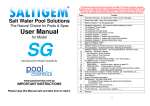
SaltiGem Manual
Salt Water Pool Solutions
The Natural Choice for Pools & Spas
User Manual
For Models
Manufactured in Western Australia by
www.poolcontrols.com.au
Page 1
SaltiGem Manual
IMPORTANT
INSTRUCTIONS
This Manual is supplied with each SaltiGem® – please keep it
safe and take the time to review it.
This Manual contains a Quick-Learn Index on Page 3. This Index contains common
questions a user might ask when maintaining a pool and using the SaltiGem®. This will
allow the user to begin operating the SaltiGem® in a quick and easy manner. You only learn
what you need to know so there is no time wasted reading the whole manual! It is however
a worthwhile read if you have the time.............if you lose this manual you’ll be sorry!!!
It is available to download from www.poolcontrols.com.au
Page
2
3
4
5
5
5
6
6
10
11
12
14
14
14
14
15
16
17
17
19
22
23
24
25
26
33
38
39
40
Content
This Index obviously.........the Quick-Learn Index is on the next page.....
Quick-Learn Index – there is no time to waste...........
What’s in the box ? (ie The packing list)
Installation Instructions – let’s hope the pool builder/installer got it right !
The SaltiGem® Power Supply
The SaltiGem® Cell
The (optional) Pool Light
The (optional) Acid Feed Valve or Pump
Before you start the unit...... How the SaltiGem® works......
SaltiGem Display and Control Overview – so you know which buttons to push.......
The LCD display – Operating Information, Warnings & Shutdowns
SaltiGem® Display and Control Details – you’ve pushed the buttons, now find out why....
Operation – Automatic & Manual
Gas Detection & Pump Shutdown
Power Failure & Timer Overview
Timer Operation Overview
AutoMode & Full Manual Mode (FMM)
The MENU System – Access & Operation
MENU Overview & Access
TIMER MENU
– access the timer
CHLOR MENU – Cell operation
LIGHT MENU
– automatic Pool Light System (light power supply is optional)
+CELL MENU
– adding a new Cell
SYSTEMDATA – information on SaltiGem® operating parameters
+ACID MENU
– acid dosing system (this system is optional)
Pool Chemistry & Balance – Salinity, Stabiliser, pH, Total Alkalinity, etc............
Maintenance – not really a dirty word !
The SaltiGem® Power Supply and optional Acid Feed System
The SaltiGem® Cell
What to Avoid Putting in the Pool
Trouble Shooting – if you ever have a problem...........
Mounting Template
Page 2
SaltiGem Manual
SaltiGem® Quick-Learn Index
The following detailed instructions can be accessed by “Question & Answer” to aid in the quick
understanding of the SaltiGem®. Many of the questions below will require the use of a MENU – to
access the MENU system see page 18 (or just press the ENT-pad – it is easy to work out !).
What can I read quickly to get me started ? pages 10, 11 & 12
Time and Automatic (or Manual) Operation:
1 How do I set the time ? page 20
2 How does the Timer work ? page 14
3 How many Filter Cycles do I need ? See page 14
4 How do I turn the pump ON (or OFF) when it is in AutoMode ? page 16
5 How do I adjust the automatic ON & OFF times ? see page 14 first, then page 21
6 What happens if the unit is OFF and I turn it ON manually ? pages 16 & 17
7 What happens if the unit is ON and I turn it OFF manually ? pages 16 & 17
8 Can I run the unit for a period of time and have it turn OFF after ? YES – page 16 & 17
9 Can I superchlorinate with the SaltiGem® ? YES – page 16 &17
10 How do I stop the unit from turning ON automatically (without turning the power off !) ?
page 17
11 Can I use an external timer ? YES – see pages 15 & 16
12 Will I lose all the saved information if the power fails ? NO – see page 14
The Chlorinator Cell:
1 How do I adjust the chlorine output of the Cell ? pages 11 & 22
2 Why does the Cell keep turning ON/OFF ? page 34 “SaltiGem® Output Control”
3 The water is cold due to the time of season and the Low Conductivity Alarm is on – what
can I do to adjust the unit for this ? page 22
4 The Cell needs to be changed – do I need to do anything to the unit ? page 24
The Pool Light Power Supply (optional):
1 How do I turn the Light ON and OFF manually ? page 11 & 23
2 Can I turn the Light ON & OFF automatically ? YES – see page 23 & 11
3 Can I pulse an LED Light ? YES – see page 11 or 22
The Acid Dosing System (optional):
1 How does the Acid Dosing System work ? page 26
2 How do I adjust (or turn OFF) the amount of acid that is being added to the pool ?
pages 26 & 27
3 I am adding buffer – how do I stop acid dosing to let the buffer mix ? page 27
4 Can I add a large dose of acid manually ? YES – see page 28
Maintaining a Swimming Pool:
1 What does my SaltiGem® need to function ? page 10 & 32 – 34
2 What chemical levels do I need to check for my pool ? page 32, 33 & 34
3 What do I do if it all goes wrong ? page 40
If the power cord is damaged the unit must be returned to POOL CONTROLS or its Service
Agent for repair.
Page 3
SaltiGem Manual
What’s In The Box ?
SaltiGem® Power Supply
SaltiGem® Cell + Housing + 40/50 Bushes Manual
Mounting Hardware
Optional:
Acid Feed Valve OR Pump
Acid Injection Fitting
Acid Tubing
Drum Fitting/Filter
NRV
The following detailed instructions can be accessed as answers to questions you may have –
simply find the question that best describes what you want to do and go to the page listed. See
Quick-Learn Index page 3. You will see that the methods used to make changes to the SaltiGem®
operation are simple, repetitive and very easy to learn – and the display will let you know what is
happening every step of the way.
Page 4
SaltiGem Manual
Installation Instructions
General Information
The SaltiGem® is manufactured from weather resistant materials and is designed for operation in
full sun and rain. However all equipment will benefit from protection from both the sun and weather
in that it will maintain its new appearance for a much longer period. The SaltiGem® Power Supply
needs to be in a well ventilated area as it is air-cooled. Installing the unit in a hot & closed shed or
box may lead to overheating and the operation of the internal protective thermal cut-out.
Note that insect intrusion (particularly ants) can cause problems with all equipment – the owner
should ensure that the pool equipment area is maintained as free of insects as possible. Insect
intrusion is not covered under the warranty.
When installing a SaltiGem® unit in conjunction with a Heatpump or Gas Heater there are special
considerations to stop acid corrosion of the heat exchanger – please refer to Installation Diagram
3 on page 7 detailing the use of a venturi injector to produce a vacuum for valve operation. An
alternative to a venturi is to use a peristaltic pump – see Installation Diagram 4 on page 8.
If the SaltiGem® unit is to be installed below water level please refer to Installation Diagram 2 on
page 5. Note that the use of a peristaltic pump may also apply – see Installation Diagram 4 on
page 8.
For most installations please refer to Installation Diagram 1 on page 6.
Installing the SaltiGem® Power Supply
Choose a location for the SaltiGem® Power Supply close enough to the Cell/Housing and filtration
pump so that both may be connected/disconnected easily. The SaltiGem® Power Supply should
not be mounted in areas where chemicals are stored (eg acid and chlorine) as vapours from these
chemicals are corrosive and may damage the electronic controls within the unit. Also ensure that
the SaltiGem® Power Supply can be connected to the mains power outlet of the pool area. Note
that this outlet must meet the current applicable Australian Standard at the time of installation.
The SaltiGem® Power Supply should be mounted vertically at least 1.5m above the ground and be
at least 3 metres from the pool water. A simple mounting kit (2 x screws/wall plugs) is provided for
mounting against a brick wall or post. The spacers are to allow some clearance between the
mounting surface and the SaltiGem® Power Supply. Please note that the rear of the SaltiGem®
Power Supply is aluminium – this can react and corrode when in contact with lime. If a mounting
surface contains lime (eg cement render) that can come into contact with the rear of the SaltiGem®
Power Supply spacers must be used to stop direct contact.
A mounting template has been provided with this unit. When mounting to a post drill a pilot hole
before attaching spacers and screws. The SaltiGem® Power Supply has keyholes for attachment –
simply hang it on the wall or post. Use 2 keyholes at the top and 1 at the bottom.
The socket outlet in the base of the SaltiGem® Power Supply is dedicated to the filtration pump
only. Do not use a double adaptor to connect another pump as this can overload the system and
void warranty.
Page 5
SaltiGem Manual
Installing/Connecting the SaltiGem® Cell
The Cell/Housing assembly should be plumbed into the pool return line after all other accessories
(and prior to any heating take-offs). Note any water flow direction on the Cell/Housing. Remember
that the Cell will need to be removed from the Housing periodically for cleaning – do not place it
where its removal can be difficult/obstructed.
The Cell Cable is connected to the Cell Connector under the SaltiGem® Power Supply. Ensure
that the 3 connections (2 for Cell Power and 1 for Gas Sensing) are colour matched and not loose.
An unmatched connection is likely to damage the Cell and a loose connection is likely to cause
arcing which may damage the entire system.
Pool Light Connection (optional): units with light power supplies have a 2-way connector in the
bottom of the SaltiGem® Power Supply. This is a safety isolated 12Vac supply suitable for pool
lights up to 150W. Simply connect the pool light cable to this connector.
Acid Dosing (optional): units with an Acid Dosing System (ADS) have an Injection Fitting and
Feed Valve/Pump which must be installed. The chemical drum/s should be mounted away from
the pool equipment to avoid possible corrosion problems.
The Feed Valve/Pump should be mounted on a wall or post close enough to allow connection to
the SaltiGem® Power Supply (connector under unit). Note that the use of either a Valve or
Pump will change the way the system can be installed – see all diagrams before
installation.
Note that there are special requirements for some installations, see all Installations Diagrams. The
feed tube, NRV and In-line Filter are then attached as shown in the diagrams.
Page 6
SaltiGem Manual
Page 7
SaltiGem Manual
Page 8
SaltiGem Manual
Page 9
SaltiGem Manual
Before You Start the Unit – Check the Following:
Always read the instructions and warnings on chemical containers before using chemicals!
Before you begin using the SaltiGem® make sure the following items are correct:
1 SALT – there must be at least 3000/4000ppm (RP/eco) of salt in the pool. This is achieved
by adding 4kg of salt for every 1000 litres (1m3) of pool volume. This amount of salt will take
time to dissolve. The process can be hastened by using the pool vacuum attachment to
collect the salt. By leaving the vacuum in the deep end of the pool the salted water will
circulate and mix within a couple of hours. Keep salt below 7500ppm to avoid shutdown.
2 CHLORINE – if it is a new installation add enough chlorine (liquid or granular) to achieve a
reading of 3ppm on an appropriate test kit. It may also be possible to run the system for at
last 24 hours to build up a residual.
3 STABILISER – it is vital that stabiliser (also known as cyanurate and cyanuric acid) be
added and maintained at 30ppm to 50ppm. This compound reduces chlorine destruction
due to sunlight. Caution: too much stabiliser will reduce the effectiveness of chlorine and
can result in poor quality water. Never exceed 80ppm.
4 pH – for chlorine to be effective the pH must be within a certain range. This is usually
between 6.8 (fibreglass/liner pools) or 7.2 (concrete/plaster) and 7.8. Check with the pool
builder or your poolshop. Adjust pH down with acid – powder, liquid sulphuric or liquid
hydrochloric. Be very careful with acid as it can be harmful and corrosive.
The above parameters are needed to get the pool started – please read the information on Pool
Balance on page 35 for more information. When the SaltiGem® is first powered it will “wake
up” with 4 Filter Cycles enabled and the Clock will be set to 10:59am. Press the ON-pad on
the front panel to start the filtration pump, then continue reading this manual (page 20) to
find out how to set the current time.
How the SaltiGem® Works:
A salt chlorinator works by putting a dc current through an electrolytic Cell in a flow of salted water.
The result is chlorine gas which dissolves almost instantly to form free chlorine in the water, and
hydrogen gas which travels to the pool and bubbles off quickly.
The SaltiGem® constantly adds a dose of chlorine to the water over the operating period of the
system. The total time of operation and hence the amount of chlorine added to the pool are
governed by the number and length of Filter Cycles (determined by the timer running the system).
For Filter Cycle information see the Timer information in this manual.
Generally a salt water pool is run for around 8 – 10 hours per day in summer and 2 – 4 hours per
day in winter. The summer operating periods are usually in the early morning and later evening.
This allows a chlorine residual to build up for pool use during the day. The filter system should
always be running when the pool is being used.
When chlorine is added to water the pH always changes – this is because chlorine is not a neutral
chemical. For a salt water system the pH will slowly rise as chlorine is produced. Gas chlorine,
trichlor & dichlor all reduce pH, while liquid chlorine and calcium hypochlorite (granular) will raise
the pH. Please review the information under Pool Balance on page 35.
Page 10
SaltiGem Manual
SaltiGem® Display and Control – a Quick Overview
The SaltiGem® uses an LCD display to provide the user with information. It has a simple “cross”
style of control with 5 press-pads to allow the user to control the various functions that are
available. The pads are backlit to show which are active at any given time. There is also a
STATUS indicator that simply shows green (OK) and red (WARNING). The reason for any
WARNING will be written on the LCD display.
Control of the way the SaltiGem® operates is achieved by the use of MENUs. The MENUs are
accessed by simply pressing ENT(ER) pad. The first to be displayed is the TIMER MENU, with
other MENUs accessed by using the UP/DOWN pads. To activate a MENU simply press ENT(ER)
again. If at any time you are unsure of what to do simply do not do anything and the unit will go
back to its normal operation after a short delay of around 10 seconds.
A typical display:
Line1 – time is 4:23pm Cell is in +Polarity and
Cell is producing at 100%.
Line2 – pump ON in Auto mode, due to turn
OFF at 10:00pm.
UP/YES & DOWN/NO Pads – these pads are
used to navigate through the MENUs and
answer YES/NO to questions on the display.
If held down for 3 seconds it will manually turn
ON/OFF the LIGHT (if unit has a light supply).
A short press will change the SaltiGem output
by ±10% (during normal operation).
ENTER Pad – this pad allows access to the
MENUs for operation of the unit. In
conjunction with the 2 pads above it allows
changes to the way the unit operates (eg
changing the ON/OFF times for Auto Mode).
ON & OFF Pads – these pads allow instant
changes to the unit operation. For example if
the unit is currently in AutoOFF the pump can
be started simply by pressing the ON pad
once.
You can learn more in the following
pages and become really dangerous!
FRONT PANEL LAYOUT
Quick Output Adjustment:
In normal operation a press of the UP/DOWN-pads will change the SaltiGem® output by +/-10%.
Note that for LED Lights requiring a power pulse to change effects you will be prompted after
turning the Light ON manually. An UP-press will pulse the light.
The operation of this unit is very simple – please take the time to understand how it works
as it can help make pool ownership the pleasure it can truly be.
Page 11
SaltiGem Manual
The LCD display – Operational Information, Warnings & Shutdowns
Note: this section describes information displayed on the LCD during normal operation. For control
function displays see the information on following pages.
Normal Operation – No Warnings or Shutdowns:
The diagram above is a sample of possible displays.
Normal Operation – With Warnings and/or Shutdowns
Gas Detection & Dry-Run Pump Shutdown:
The first display above shows the Cell being turned OFF after Gas is detected for approximately
10 seconds. If Gas is still detected after approximately 2 minutes the Pump will also be turned
OFF. To re-start the Pump simply press the ON-pad (as instructed by the display). This will reset
the warnings and allow the Pump to run (for a maximum of 3 minutes if Gas is still detected).
Low Conductivity & (optional) Cell LoCond Shutdown:
There are 2 levels of Low Conductivity detected. The first level results in the first display. The
second level results in the Cell being turned OFF (if that option is selected at the factory). To start
the Cell again simply press the ON-pad (as instructed by the display).
High Conductivity:
(note that this will turn the unit off to stop overheating)
If the above Warning is present the unit has shut down to avoid an overload (mandated by
electrical standards). Check the salinity and water temperature. Salinity should be kept below
7,500ppm. The SaltiGem® is not designed for operation in seawater or brine.
Page 12
SaltiGem Manual
Operation – Automatic & Manual
Gas Detection & Pump Shutdown
The SaltiGem® unit will detect a NO FLOW (water) condition by checking for gas in the Cell
Housing. When gas has been detected for more than 10 seconds the Cell will be turned OFF. If
gas is detected for a further 2 minutes (approx) the Pump will also be turned OFF. The STATUS
light will be red to warn of a problem – see page 12.
Power Failure Operation & Timer Overview
The SaltiGem® unit comes with a timer function built into the operating software. The timer is a
24-hour type with quartz-crystal control and has a battery back-up in case of a power failure. The
battery is a rechargeable NiMH type so it will never need replacing.
If a power failure is of a short duration (a day or two) the SaltiGem® will keep time and maintain
AutoMode functions. If a Filter Cycle is active when power is returned the pump will be turned ON.
If a power failure occurs over an extended period of time the SaltiGem® will save all its operating
information to a special memory. When power eventually returns it will wake up remembering
everything except the current time – it will show the time at which the Back-Up Power was
exhausted. If the unit is in AutoMode the pump will be OFF waiting for the next Filter Cycle to
become active. If the unit is in Full Manual Mode the pump will be turned ON immediately.
For future reference information that is retained in the special memory can not be lost and is said
to be non-volatile. Information that can be lost during an extended power failure is said to be
volatile.
Power Fail Operation is shown in the following diagram:
The SaltiGem® can operate automatically or manually in AutoMode, or it can be set to operate in
Full Manual Mode (FMM). Both modes are non-volatile – a unit will always wake up in the mode to
which it is set. Modes can be changed by the user however it is unlikely that this will be required –
nearly all units (in Australia) will use the built-in timer.
Page 13
SaltiGem Manual
Timer Operation Overview
Note: SaltiGem® uses 24-Hour time
Selecting Full Manual Mode (FMM) or AutoMode
Most units will already be set for AutoMode operation. To change from one mode to the other:
• Press the ON-pad for 4 seconds to change to FMM
• Press the OFF-pad for 4 seconds to change to AutoMode
ON & OFF Times for AutoMode
The automatic operation of the SaltiGem® is uses 4 ON/OFF times each of which make up a Filter
Cycle (FC). Each FC has a start time (ON) and a stop time (OFF). Each FC has a number of 1 to 4
so that the user can select how many FCs to enable. If 3 FCs are enabled then FC1, FC2 & FC3
will determine the SaltiGem® automatic operation. If only 1 FC is enabled then only FC1 will
determine the SaltiGem® automatic operation.
If an FC has an ON time the same as another FC’s OFF time then they can combine to form one
longer FC. For example let us assume that FC1 has an ON time of 6am and an OFF time of 8am,
and FC2 has an ON time of 8am and an OFF timer of 11am. If the user enables only 1 FC then
the SaltiGem® will turn the pump ON at 6am and OFF at 8am. If the user enables 2 FCs the
SaltiGem® will still turn the pump ON at 6am but it will now turn OFF at 11am – the pump has now
run for an extra 3 hours.
This method of automatic operation is useful for increasing/decreasing the filtration hours of a pool
as the seasons change – with no need to actually change the individual ON/OFF times. It is far
simpler to enable/disable Filter Cycles.
The SaltiGem® comes with preset FCs (4 are enabled for a total of 8 hours per day operation).
These are shown in the diagram below along with possible uses. Please note that pool chlorine
demand varies significantly and these settings are a guide only.
The Filter Cycle ON & OFF times are fully adjustable – please see page 21. The diagram above
can be used to help plan alternative Filter Cycle timing to suit your pool. More on page 22.
Page 14
SaltiGem Manual
AutoMode and Full Manual Mode
Full Manual Mode (FMM)
FMM is used in situations where an external timer is required to run the SaltiGem®. FMM is a
setting which starts the pump immediately on the application of power to the unit. A unit in FMM
mode can have the pump turned OFF. This will mean that the pump will not turn back ON unless it
is manually turned ON by the ON pad or a long power failure occurs.
The operation of the ON/OFF-pads in Full Manual Mode is shown below:
(Note: for clarity only Line2 of the LCD is shown)
AutoMode
The Timer in the SaltiGem® is very versatile and easy to use. It has 4 adjustable Filter Cycles that
can be accessed from the TIMER MENU. All Filter Cycles can be overridden manually. Filter
Cycle 1 is always enabled. The other 3 Filter Cycles can be enabled or disabled in order (ie select
1, 2, 3 or 4 Filter Cycles to be enabled). This allows a simple increase or decrease in running
times to be achieved without adjusting the Filter Cycle ON/OFF times – simply add or remove
cycles ! See page 20 for details.
In AutoMode the SaltiGem® will START (at first power-up or after a long power failure) with the
pump OFF. It will then wait for the next available ON-time to start the pump and the rest of the
system. If there is a power failure the system will continue to keep time for a number of days.
During this time the pump ON/OFF-times will still be checked. When power is restored the system
will wake up and turn the pump ON if it is during a Filter Cycle.
Automatic Operation:
During Automatic Operation Line2 of the LCD will display whether the Pump is ON or OFF and the
next OFF or ON time:
The displays are read as: “Auto OFF next ON at 4:30pm” OR “Auto ON next OFF at 10pm”
Page 15
SaltiGem Manual
Manual Operation While In AutoMode:
It is often necessary to turn the pump ON/OFF Manually when it is in AutoOFF/ON. This is a very
simple operation – press the ON/OFF pad once. The pump will start or stop immediately.
The unit will still be in AutoMode and will respond to the next AutoOFF/ON – it will not remain
ON/OFF indefinitely (unless that is desired see page 17).
The following diagram shows what will happen to Line2 of the LCD for a Manual ON/OFF during
Auto OFF/ON and Manual OFF/ON:
Operate Pump Manually For a Number of Hours:
It is sometimes desirable to run the pump for a period of time and then turn it OFF while still in
AutoMode. The pump will then turn back on at the next AutoON. This feature can be used to
superchlorinate over a 24, 36 or 48 hour period, or simply to run the pump for a coupe of hours
while the children have a swim.
To achieve this the unit should be in AutoON or ManON – simply press the ON-pad and Line2 of
the LCD will read “Man ON FOR 01Hrs”. Another press of the ON-pad (without release) increases
the number of hours that the pump will operate in the following sequence: 1, 2, 3, 4, 5, 6, 12, 18,
24, 36 & 48 and then the sequence repeats from 1 again. To lock in the selected number of hours
the ENTER-pad must be pressed. If this is not done the SaltiGem® will revert to AutoMode
(ManON→AutoOFF) operation in approximately 10 seconds.
When in this mode of operation the time period can be changed by simply pressing the ON-pad
and repeating the above steps.
This mode can be stopped by simply pressing the OFF-pad – this will return the unit to
ManOFF→AutoON.
It should be noted that the LCD will count down the time left to run in this mode. When it gets to 1
hour it will then count down the remaining minutes prior to the pump being turned off and the unit
reverting to AutoOFF→AutoON.
The following diagram shows Line2 of the LCD as the various pads are pressed:
Page 16
SaltiGem Manual
Turn Pump OFF with No AutoON (Pump OFF indefinitely):
If the pump is required to be OFF indefinitely (perhaps while work is being carried out on pool
equipment) simply press the OFF-pad 1 or 2 times until the LCD reads “Man OFF→ NO Auto”:
Note that if a long duration power failure occurs this setting is volatile – the SaltiGem® will wake in
AutoOFF→AutoON.
Page 17
SaltiGem Manual
The MENUs: Access & Operation
MENU Overview & Access
The MENU system is a logical way of allowing easy access to the settings required to run the
SaltiGem®. The MAIN MENUs are accessed by pressing the ENT(ER)-pad:
The SaltiGem has 6 MAIN
MENUs (shown in the
diagram at left) and each
MAIN MENU may have SUBMENUs (described in the
following pages). The MAIN
MENUs are accessed from
normal operation by a single
SEL-pad press. The first
MENU to be displayed is the
TIMER MENU. Other
MENUS are available by
pressing the UP/DOWNpads.
Once the desired MENU is
displayed a SEL-pad press
will enter that MENU.
If the SEL-pad is not pressed
the SaltiGem will go back to
normal operation without any
changes being made.
Once a MENU is entered
both lines of the LCD will be
used to display any SUBMENUs or other information.
Page 18
SaltiGem Manual
The TIMER MENU
Accessing the TIMER MENU:
The TIMER MENU is accessed by a ENT(ER)-pad press from the MAIN MENU. Once the TIMER
MENU is accessed the fist Sub-MENU appears in Line2 – SET TIME. There are 3 Sub-MENUs:
SET TIME, FILTER CYCLES & ADJUST CYCLES. These Sub-MENUs are accessed by the
UP/DOWN-pads and entered by pressing the ENT-pad.
The following diagram shows how to access the Sub-MENUs:
Note that the FILTER CYCLES Sub-MENU above has an associated number – 2. This is the
number of Filter Cycles that are currently active. This number can have a value of 1 to 4.
While the Sub-MENUs are in the display they can be entered by a single ENT-pad press.
Page 19
SaltiGem Manual
Setting the Time – the SET TIME Sub-MENU:
To set the time of day simply go to the SET TIME Sub-MENU and press the ENT(ER)-pad. Line2
of the LCD will now read “SET TIME HOURS” – simply use the UP/DOWN-pads to adjust the
Hours Value on the LCD. When complete a ENT-pad press will then move to show “SET TIME
MINUTES” on Line2 and the UP/DOWN-pads can be used to adjust the Minutes Value. When
complete press the ENT-pad to return to normal operation.
The diagram below shows how to set the time:
Enabling Filter Cycles – the FILTER CYCLES Sub-MENU:
Using the ENT(ER)-pad and the UP/DOWN-pads go the FILTER CYCLES Sub-MENU (Line2 of
LCD) and press ENT-pad – see “Accessing The Timer Menu” page 19. It will have an associated
number – this is the number of enabled Filter Cycles (FCs). Using the UP/DOWN-pads this
number can be easily changed. To make the change take effect the ENT-pad must be pressed –
normal operation is then resumed. The effect of Filter Cycles is described on page 15.
Page 20
SaltiGem Manual
Changing the Filter Cycle ON & OFF Times – the ADJUST CYCLES Sub-MENU:
The ADJUST CYCLES Sub-MENU allows the user to change the ON & OFF times of the Filter
Cycles (FCs) that are enabled. For example if there are 2 FCs enabled the user can adjust FC1
and FC2. To adjust all FC ON & OFF times all FCs must be enabled – see “Enabling Filter Cycles”
page 20.
Using the ENT(ER)-pad and the UP/DOWN-pads go the ADJUST CYCLES Sub-MENU (Line2 of
LCD) – see “Accessing The Timer Menu” page 19. When the ENT-pad is pressed Line1 of the
LCD will now read the ON time of the Filter Cycle number shown at the end of Line2. This is
adjusted with the UP/DOWN-pads. Once the desired time is reached the ENT-pad is pressed to
store the ON time and the OFF time is then displayed. The OFF time is adjusted in the same way
as the ON time. After ON/OFF times for the first enabled FC are adjusted the next enabled FC ON
time is shown on the LCD. This process continues until all FCs are adjusted.
Note: Only enabled Filter Cycles are available for adjustment (starting with FC1).
ENT-pad must be pressed to store the changed times and move through the process.
If Times are to remain unchanged simply press ENT-pad and the original time is kept.
Filter Cycle Planner:
Page 21
SaltiGem Manual
The CHLOR MENU
The CHLOR MENU is used to adjust the chlorine output of the SaltiGem®, and to adjust a
temperature compensation value that helps to maintain the accuracy of the STATUS warnings
when the water temperature gets lower over the colder months.
Accessing the CHLOR MENU:
The CHLOR MENU is accessed in the same way that all other MENUs are accessed – a ENT-pad
press will shift to the MENU SYSTEM (TIMER MENU), then an UP-pad press will shift to the
CHLOR MENU. It is also possible to access this MENU with 5 DOWN-pad presses. Once the LCD
Line1 reads “hh:mm CHLOR MENU” – press ENT-pad to enter.
There are 2 adjustments in the CHLOR MENU: Output and Water Temperature (for system
compensation).
Setting the Chlorine Output of the SaltiGem®
Line2 will now read “SET OUTPUT =100%”. The output is adjusted using the UP/DOWN-pads.
The output is adjustable from OFF to 100% in 10% steps. Once the desired output is reached
press ENT-pad to lock in the value and move to the next adjustment.
Setting the Water Temperature
Line2 will now read “ADJUST TEMP=26°C”. The UP/DOWN -pads will allow adjustment from 12°C
to 26°C in 2°C steps. This value is used to provide system compensation for colder water – when
water temperature reduces (eg in winter) the conductivity will decrease. Without compensation the
unit will warn of Low Conductivity before it should.
Page 22
SaltiGem Manual
The LIGHT MENU
The LIGHT MENU is used to select and adjust the automatic light control. The light power supply
can be turned ON/OFF like a Filter Cycle, as well as being manually controlled. If the light
automation is selected the light power supply will be controlled by the ON and OFF times. If the
light is turned ON manually it will still be turned off at the OFF time. If the light automation is not
selected the light can only be controlled manually.
Manual Light Operation
During normal operation the light can be turned ON manually by pressing the UP-pad for
approximately 4 seconds. It can be turned OFF by pressing the DOWN-pad for 4 seconds.
Note that for LED Lights requiring a power pulse to change effects you will be prompted after
turning the Light ON manually. An UP-press will pulse the light.
Accessing the LIGHT MENU:
The LIGHT MENU is accessed in the same way that all other MENUs are accessed – a ENT-pad
press will shift to the MENU SYSTEM (TIMER MENU), then 2 UP-pad presses will shift to the
LIGHT MENU. It is also possible to access this MENU with 4 DOWN-pad presses. Once the LCD
Line1 reads “hh:mm LIGHT MENU” – press ENT-pad to enter.
Line2 will now read “AUTO ? Y/N”. To disable automatic light operation press the DOWN-pad.
Line2 will read “Auto OFF” for short period then the system will return to normal operation and the
light will only respond to Manual ON/OFF.
To enable automatic light operation press the UP-pad. Line2 will read “Auto ON” for short period
before displaying “ON hh:mm”. The ON-time is adjusted using the UP/DOWN-pads. A ENT-pad
press will lock in the new ON-time and the LCD will read “ON 19:30OFFhh:mm”. The OFF-time is
adjusted by using the UP/DOWN-pads. A ENT-pad press will lock in the new OFF-time and the
system will revert to normal operation.
Page 23
SaltiGem Manual
The +CELL MENU (The Add Cell Menu)
The +CELL MENU is used when a new Cell is attached t the SaltiGem®. The SaltiGem® keeps
statistics on the amount of time the Power Supply and Cell have operated. This data is nonvolatile. Up to 3 new Cells can be added over the life of the unit. It is vital that the system only
be used when adding a new cell. Information stored can be used to help validate a warranty
claim. Average Cell life is designed to be 9,000 to 10,000 hours (see page 32 for Cell care).
Accessing the +CELL MENU:
The +CELL MENU is accessed in the same way that all other MENUs are accessed – a ENT-pad
press will shift to the MENU SYSTEM (TIMER MENU), then 3 UP-pad presses will shift to the
+CELL MENU. It is also possible to access this MENU with 3 DOWN-pad presses. Once the LCD
Line1 reads “hh:mm +CELL MENU” – press ENT-pad to enter.
The LCD will read on Line1:
on Line2:
“CELL REPLACEMENT” and
“ADD NEW CELL Y/N”
A DOWN-pad press will make the SaltiGem® ignore the Menu and revert to normal operation.
An UP-pad press will enter the Menu and the LCD will read a warning for a few seconds –
This is followed by
Line1:
Line2:
“SEE MANUAL UNDER” and
“<CHANGING CELL >”
Line1:
Line2:
“CONFIRM?
Y/N” and
“<CHANGING CELL >”
A DOWN-pad press will make the SaltiGem® ignore the Menu and revert to normal operation.
An UP-pad press will store the old Cell data and reset for the new Cell. The LCD will read –
Line1:
Line2:
“CONFIRMED
OK” and
“<CHANGING CELL >”
The unit will then revert to normal operation.
Page 24
SaltiGem Manual
SYSTEMDATA
SYSTEM DATA is used to display system information on the LCD. It is included as a tool for the
user and service technician to determine various system settings with ease.
Accessing SYSTEMDATA:
SYSTEMDATA is accessed in the same way that all other MENUs are accessed – a ENT-pad
press will shift to the MENU SYSTEM (TIMER MENU), then 4 UP-pad presses will shift to the
+CELL MENU. It is also possible to access this MENU with 2 DOWN-pad presses. Once the LCD
Line1 reads “hh:mm SYSTEMDATA” – press ENT-pad to enter.
When selected SYSTEMDATA will show a number of displays on the LCD:
•
Display 1 – The type of SaltiGem®, the Cell size and output setting (Line2)
POOL CONTROLS followed by Output (0 – 10 for 0 – 100%) (Line1)
•
Display 2 – Acid Dosing information (optional – will display only if it is an acid dosing unit)
•
Display 3 – Cell & Power Supply statistical information
•
Display 4 - Previous Cells statistics (only available after the first new Cell is added)
A typical set of displays will look like this:
Page 25
SaltiGem Manual
The +ACID MENU - Optional (The Acid Dosing Menu)
The +ACID MENU is used to select and adjust the Acid Dosing System (ADS). The ADS is a timed
acid dosing system using either a vacuum valve or peristaltic pump. As chlorine is produced the
pool pH will go up slowly. This can be offset by small doses of acid added to the pool.
An algorithm estimates the amount of acid that is needed per dose. It is vital that the pool pH is
checked regularly – THIS SYSTEM MUST BE ADJUSTED TO SUIT YOUR POOL. See the
section on ACID DOSING on page 27 and POOL BALANCE on page 35. Once the ADS is
adjusted maintenance should be minimal.
Accessing the +ACID MENU:
The +ACID MENU is accessed in the same way that all other MENUs are accessed – a ENT-pad
press will shift to the MENU SYSTEM (TIMER MENU), then 5 UP-pad presses will shift to the
+ACID MENU. It is also possible to access this MENU with 1 DOWN-pad press. Once the LCD
Line1 reads “hh:mm +ACID MENU” – press ENT-pad to enter. After entering the +ACID MENU
Line1 of the LCD will read “hh:mm DOSE ONLY”.
The +ACID MENU is relatively long compared to the other MENUs but is simple to use. If you do
not want to change any values simply pressing the ENT-pad (or DOWN-pad for NO) will move
past each section. If you are worried about making a change before checking with this manual
simply do not touch anything and normal operation will resume after a few seconds.
Acid Dosing – Turning it OFF (and back ON):
After entering the +ACID MENU Line2 of the LCD will read: “DOSER ON ? Y/N”. Pressing the
DOWN-pad will exit the MENU after turning the ADS OFF (ie no acid will be dosed) – Line2 will
read “DOSER OFF” before normal operation resumes. Pressing the UP-pad will result in Line2
reading “DOSER ON” for a short period before the ADS moves on to the next Sub-MENU – ADD
BUFFER, see next Sub-MENU.
Page 26
SaltiGem Manual
The Add Buffer Sub-MENU:
After turning the ADS system ON Line2 of the LCD will read “ADD BUFFER? Y/N”. Pressing the
DOWN-pad (NO) will move the system to the ADJUST AutoDOSE Sub-MENU. Pressing the UPpad (YES) will indicate that buffer has been added and the ADS will stop acid dosing for 24 hours
of SaltiGem® operation (see POOL BALANCE on page 35). The system then moves on to the
ADJUST AutoDOSE Sub-MENU.
Automatically Dose Acid – the ADJUST AutoDOSE Sub-MENU:
This Sub-MENU adjusts the amount of acid added to the pool each time the system doses. The
adjustment is from 15mL/dose to 300mL/dose in 15mL/dose increments.
To enter the ADJUST AutoDOSE Sub-MENU simply press the UP-pad to indicate YES. Pressing
the DOWN-pad (NO) will move the system to the next Sub-MENU: ADJUST Man DOSE.
Once into the ADJUST AutoDOSE Sub-MENU the LCD display will read –
Line1: “hh:mm Auto DOSE”
Line2: “
xxx mL/DOSE”
Use the UP/DOWN-pads to adjust the xxx value and press ENT-pad to lock in value and move to
next Sub-MENU: ADJUST Man DOSE.
Page 27
SaltiGem Manual
Adding Acid Manually – the ADJUST Man DOSE Sub-MENU:
This Sub-MENU adjusts the amount of acid added to the pool as an immediate dose. The
adjustment is from 0mL (OFF) to 750mL in 15mL increments.
This function is useful for priming acid lines after an acid drum change, and for adding a large
dose of acid after adding buffer (see POOL BALANCE page 35).
To enter the ADJUST Man DOSE Sub-MENU simply press the UP-pad to indicate YES. Pressing
the DOWN-pad (NO) will move the system to the next Sub-MENU: ADJUST Man DOSE.
Once into the ADJUST Man DOSE Sub-MENU the LCD display will read –
Line1: “hh:mm Man DOSE”
Line2: “
xxx mL”
Use the UP/DOWN-pads to adjust the xxx value and press ENT-pad to lock in value and move to
back to normal operation. The ADS should begin dosing acid to the pool within 5 seconds.
Page 28
SaltiGem Manual
Pool Chemistry for the SaltiGem®
Salt
Operating the SaltiGem® Cell in pool water with less than the minimum recommended salt level
will increase the wear on the Cell. Salt is the essential chemical needed for SaltiGem® operation. It
uses the salt to manufacture chlorine. Not enough salt means not enough chlorine – and not
enough salt also means faster Cell wear. Keep salt below 7500pm to avoid possible shutdown.
The minimum salinity for the SaltiGem® eco is 4000ppm, and for the RP it is 3000ppm.
Salinities below these values will result in early Cell failure.
Salt is not consumed in the SaltiGem® process. A simplistic view of the SaltiGem® process is that
energy is added to split the salt to make free chlorine and the chlorine is then used to destroy
bacteria, fungi, viruses and other unwanted things in the pool water. When the free chlorine has
done its job it goes to being salt again – ready to be recycled again and again. Salt leaves the pool
through backwashing, splashing and on bathers as they leave (and leaks if you have them).
The SaltiGem® has a Low Conductivity Warning to advise when salt may be needed. Conductivity
falls with salinity and temperature. If the Lo COND warning is ON check the water temperature
and adjust the temperature compensation (page 23) before checking the salt level. This is
important over the winter months.
Operating the SaltiGem® without enough salt will void the warranty – it is the owner’s responsibility
to ensure that correct salt levels are maintained.
Stabiliser (cyanuric acid)
All outdoor pools must have a stabiliser level of 30ppm – 50ppm.
Stabiliser helps to retain chlorine in the pool by slowing the destructive effect of sunlight. Without
stabiliser it will be difficult or impossible to keep a chlorine residual in the pool – the SaltiGem®
may need to be run for 3 – 4 times as long.
Stabiliser is not used up in any process – it leaves the pool in the same way that salt does. It
should only need topping up when the salt does.
High levels of stabiliser will cause problems in a salt pool – never allow stabiliser to rise beyond
80ppm. Stabiliser can enter the pool in chemically added chlorine – both dichlor and trichlor
(chlorines) are stabilised and will leave a stabiliser residual in the pool.
Adding Stabiliser – to add 10ppm: add 100g for every 10,000 litres (10m3). Stabiliser is slow to
dissolve and should be added by placing in an old stocking and hanging over a pool return. If this
can not be done the stabiliser can be added slowly to the skimmer box after the filter has been
backwashed/cleaned. DO NOT BACKWASH THE FILTER FOR AT LEAST 7 TO 10 DAYS WHILE
THE STABILSER DISSOLVES OTHERWISE IT WILL BE LOST TO THE BACKWASH PIT !
ALWAYS GET THE LEVEL CHECKED BEFORE ADDING MORE !
Page 29
SaltiGem Manual
pH & Total Alkalinity (TA)
Incorrect pH levels can damage a pool – see information under POOL BALANCE on page 35.
Read instructions on chemical containers before use – be safe around chemicals !
pH
Correct pH must be maintained to allow free chlorine to be effective. If you allow the pH to rise
above 8 you will need many times the usual amount of chlorine for sanitation. Correct pH will also
help to prevent problems such as black spot, cloudy water and staining.
pH is adjusted down with hydrochloric acid, liquid sulphuric acid or dry acid (sodium bisulphite).
NOTE: use of sulphuric acid will increase sulphate levels in pool water. In areas where barium is
present in the water sulphate can lead to the formation of an insoluble coating (of barium sulphate)
over the Cell which will stop the Cell operating.
pH is adjusted up with soda ash (sodium carbonate) and buffer (sodium bicarbonate). Buffer also
increases TA.
Total Alkalinity (TA)
TA is related to pH in that it stops the pH from varying quickly with small additions of acidic or
alkaline chemicals.
When the TA is low it is almost impossible to control the pH. This can lead to serious
To raise the TA buffer (sodium bicarbonate) is added. This must be done slowly as buffer will also
cause the pH to rise. As an approximate rule every increase of 20ppm of TA will also cause a 0.1
rise in pH. Once buffer is added it should be left to mix in the pool for a few hours before reducing
the pH. Test kits are available to measure both TA and the acid demand for this operation – or you
can go to your local poolshop for advice.
To lower TA – add acid.
Chlorine
Low chlorine levels can mean that the pool is unsanitary (not safe to swim in). High
chlorine levels can lead to bather irritation. Follow Health Department guidelines.
SaltiGem® produces chlorine at a rate determined by the Cell size:
Cell Size
SaltiGem®
Model
eco
16
20
24
RP
20
30
Output in Equivalent Chlorine
Each hour of operation
Over 8 hour period
Gas
Granular Liquid
Gas
Granular Liquid
(100%)
(65%)
(12%)
(100%)
(65%)
(12%)
g/Hr
litres
g/Hr
mL/Hr
g
g
16
20
24
30
25
31
37
50
Page 30
133
167
200
250
128
160
192
240
197
246
295
369
1.07
1.33
1.60
2.00
SaltiGem Manual
Running Times:
The amount of chlorine being added to the pool each day is determined by the Cell size and the
number of hours that the SaltiGem® is operated. Chlorine is added to a pool to keep the water
sanitised – it does not clean the water. The filter is what keeps the water looking good. Most
pollutants (dust, sand, vehicle pollution, etc) enters a pool from the atmosphere – and it does this
24 hours per day, 7days per week........ The filter needs to operate for a reasonable number of
hours per day to keep the water looking good.
As sunlight destroys chlorine (see section about Stabiliser on page 32) it is recommended that the
SaltiGem® be run mostly in the evening. The SaltiGem® comes preset to run from 6am to 8am in
the morning and from 5pm to 11pm in the evening (17:00 to 23:00).
Always run the filter when using the pool.
To keep the pool looking good over the swimming season it is recommended that your filter and
SaltiGem® be operated for at least 8 hours per day. In very hot weather and/or with large bather
loads the pool may need to run for 10 or more hours per day, depending on the Cell size. In these
cases extra chlorine can also be added.
If there are adverse local conditions – such as windborne dust and debris or heavy traffic pollutionthe chlorine demand will be higher than normal. You will likely need to operate the filter for longer
periods.
Controlling the Chlorine Residual:
There are two ways of controlling the amount of chlorine entering the pool – by altering the running
times and by reducing the SaltiGem® Output. If the pool chlorine residual tests high you can
reduce the operating time and/or decrease the Output. If the chlorine residual tests low and the
output is already at maximum you will need to increase the operating time and/or add
supplementary chlorine.
SaltiGem® Output Control:
The LCD display usually shows the amount of chlorine being produced by the Cell as a
percentage of its maximum. This is the not the same as the SaltiGem® Output. The Output Control
turns the Cell ON/OFF over a short period of time. The Output setting determines how long the ON
time is – for example if the Output setting is 60% the Cell will be ON for 60% of the period and
OFF for 40% of the period. In this way the Cell output can always be checked to see if it is
operating correctly. This is why the Cell will turn ON/OFF if the SaltiGem® Output is below 100%.
Superchlorination:
When bathers enter a pool there is a reaction between nitrogen/ammonia compounds from the
bathers and the chlorine in the pool. These reactions form chloramines (also called combined
chlorine) which are responsible for the “chlorine” odour and for some minor irritations. These
compounds can be broken down by adding free chlorine to a level above 5ppm. The addition of a
shock dose to chlorine to achieve this is called superchlorination.
With the SaltiGem® process levels of chlorine at the Cell anodes far exceed 5ppm and so a lot of
chloramines will be broken down as water passes the Cell. If the combined chlorine level becomes
high simply add a shock dose of chlorine or run the SaltiGem® for a long period overnight (see
page 16 for specific Timer settings for this).
Page 31
SaltiGem Manual
Pool Balance
The water in the pool needs to be maintained for the safety of swimmers and the reliability of the
equipment and the pool itself. Concrete/plaster pools are particularly susceptible to pool balance
problems. The balance in this case is the need of the water to take on or give up calcium. The
Langelier Index is used to determine water balance. If the water does not have enough calcium it
is said to be corrosive (or aggressive) and if it has too much it is said to be scaling. Corrosive
water will look to obtain calcium from any source – in the case of a concrete/plaster pool it will be
from the pool walls. A pool with continuously corrosive water will eventually have its walls begin to
turn to dust/sand as the calcium that holds the wall material together is leached away. Conversely
a pool with scaling water will tend to precipitate calcium onto its surfaces – the walls, the sand in
the filter and the insides of the plumbing.
1 SALT – there must be at least 4000ppm of salt in the pool. This ensures that the SaltiGem®
will operate correctly. If there is not enough salt in the pool the Cell will wear out faster –
this is why the SaltiGem® has a Low Conductivity warning. Conductivity falls with salinity.
2 CHLORINE – check with local health regulations for minimum and maximum values.
Generally 3ppm (stabilised, 1.5ppm unstabilised) will maintain a healthy pool.
3 STABILISER – it is vital that stabiliser (also known as cyanurate and cyanuric acid) be
added and maintained at 30ppm to 50ppm. Never exceed 80ppm. DO NOT ADD TO
INDOOR POOLS AS THERE IS NO DIRECT SUNLIGHT.
4 pH – for chlorine to be effective the pH must be within a certain range. This is usually
between 6.8 (fibreglass/liner pools) or 7.2 (concrete/plaster) and 7.8. Check with the pool
builder or your poolshop. pH is the one of major influences on water balance. As the pH
falls the water balance tends toward becoming corrosive. A higher pH is usually better to
avoid corrosive water. Raise pH with soda ash (sodium carbonate) and buffer (sodium
bicarbonate, also raises TA). Lower pH with acid.
5 TOTAL ALKALINITY – also known as carbonate hardness or TA for short. This is
necessary to help control pH. As TA falls water becomes more corrosive. Recommended
level is between 80 and 120ppm. See below for the relationship between TA and pH.
Increase TA with buffer (sodium bicarbonate).
6 CALCIUM HARDNESS – this can be controversial. The Australian Standard AS3633 states
that calcium hardness can be 80 to 500ppm. However salt Cells become scaled due to
calcium in the water. For the purpose of keeping maintenance to a minimum it is
recommended that calcium levels be left as low as possible (ie around 80ppm). See below.
The above parameters can be mixed and matched to achieve balanced water. The amount of
calcium dissolved in the water is determined mostly by the pH. At high pH calcium will simply
precipitate out of the water – this can sometimes be seen as cloudy water after adding a large
amount of buffer. To keep the pH of a pool at the lower end of the range requires a constant
addition of acid over time. The addition of this acid reduces the TA and so buffer must also be
added to stop the pH from becoming uncontrollable. This is a bit like a fast merry-go-round. To
reduce the speed (and save money and time) keep the pH at the higher end of the range. This
reduces the need for acid and buffer, and also reduces the amount of calcium needed to finally
balance the water. This means that it is likely that calcium will not need to be added to the pool
and so Cell maintenance can be minimised.
The following information allows the calculation of the Langelier Saturation Index for the pool.
Page 32
SaltiGem Manual
The Langelier (Calcium) Saturation Index (LSI):
The calculation of the Index value is simplified by using a number of pre-calculated factors that
can be added/subtracted to give an Index value. It should be noted that poolshop water reports
generally use the LSI in their water balance computations. Some systems do not include the TDS
and this is necessary for salt water pools. A negative LSI indicates corrosive water and a positive
LSI indicates scaling water. It is better for pool water to be slightly scaling than corrosive.
LSI = pH + TAF + CF – TDSF – TF – 9.3
Total Alkalinity
Factor
TA (ppm)
TAF
60
1.78
70
1.84
80
1.9
90
1.95
100
2.00
110
2.04
120
2.08
130
2.11
140
2.15
150
2.18
160
2.20
170
2.23
180
2.26
190
2.28
200
2.30
where pH is the pool water pH
TAF is the Total Alkalinity Factor
CF is the Calcium Factor
TDSF is the *TDS Factor
TF is the Temperature Factor
*Total Dissolved Solids includes salt level
Calcium Hardness
TDS Factor
Temperature Factor
Factor
Hardness (ppm)
CF
TDS (ppm) TDSF
Temp (°C)
TF
40
1.20
500
0.17
12
2.34
50
1.30
1000
0.20
14
2.30
60
1.38
2000
0.23
16
2.26
80
1.50
2500
0.24
18
2.22
100
1.60
3000
0.25
20
2.18
120
1.68
3500
0.25
22
2.15
140
1.75
4000
0.26
24
2.11
160
1.80
4500
0.26
26
2.07
180
1.86
5000
0.27
28
2.03
200
1.90
5500
0.27
30
1.99
250
2.00
6000
0.28
32
1.96
300
2.08
6500
0.28
34
1.92
400
2.20
7000
0.28
36
1.88
500
2.30
7500
0.29
38
1.84
600
2.38
8000
0.29
40
1.81
In general if the LSI in the range of –0.5 < LSI < 0.5 then the water can be considered balanced.
An example: a salt pool has a TDS of 4500ppm, is at a temperature of 26°C, has a TA of 100ppm
and a calcium hardness of 80ppm. What should its minimum pH be ?
The minimum pH will be when the LSI is at its minimum ie –0.5:
–0.5 = pH + 2 + 1.5 – 0.26 – 2.03 – 9.3
–0.5 = pH – 8.09
which simplifies to:
(ie pH = 7.6)
The minimum pH for balance is 7.6. If perfectly balanced water were required the LSI must be 0.
In this case the pH would need to be 8.09, which is too high for a pool as the chlorine would not be
very effective. If an LSI of 0 were required a change would need to be made to the pool balance. If
we take the example above and want the pH to be 7.8 (for LSI = 0) the simplest change we can
make is to increase the TA:
0 = 7.8 + TAF + 1.5 – 0.26 – 2.03 – 9.3
which simplifies to:
0 = TAF – 2.29
(ie TA = 190)
In the above case the TA would need to be very high and so some calcium may need to be added.
If we make the TA 130ppm and add 40ppm to the calcium hardness the pool will be balanced.
Page 33
SaltiGem Manual
Some Pool Additive Information:
Algaecides
These additives either kill algae or remove the conditions required for growth.
Copper based algaecides – these pose minimal risk to the Cell of your SaltiGem®. However
copper (and a lot of other metals) can be precipitated from pool water as the pH rises. This means
that if copper is added and your pool pH rises well above the recommended range there may be
staining to the pool surfaces. Should not affect the Cell.
Quaternary ammonium compounds – usually benzalkonium chloride. This compound is generally
an algae preventive treatment. It is a surfactant (similar to a detergent) and can cause foaming in
pools and spas. Care should be exercised when using this compound as it can turn cloudy in
water when exposed to high chlorine residuals. If a pool has a slower water flow it may turn cloudy
in the Cell Housing due to the high level of chlorine present there. Should not affect the Cell.
Phosphate Removers – usually lanthanum salts. This compound will precipitate all phosphate from
the pool water and so there will be no essential nutrient for the algae to grow. It is recommended
that the Cell be turned off for several days while the pool is being treated.
Citric Acid (black spot remover) – using this additive will stop a chlorine residual from being
measured for up to 4 – 6 weeks. Should not affect the Cell.
Polyhexanide Hydrochloride – this is the same as polyhexamethylene biguanide (previously sold
under the name “Baquacil”). This is not compatible with chlorine. It is used in non-chlorine sanitiser
systems (with use of oxygen based shock compounds).
Shock Treatments
These compounds are based around chlorine or oxygen (usually peroxides). They act to increase
the chlorine residual or impart peroxide to the water. A common oxygen-based additive is
potassium monopersulphate (monopersulphate for short). In the presence of salt this will activate
chloride to free chlorine. Should not affect the Cell.
Pool Flock (coagulants)
These compounds are used to bind small particles together so that they can be filtered from the
pool water. Common ones are alum (aluminium sulphate) and polymer-based surfactants. Should
not affect the Cell.
Anti-Stain & Anti-Scale Compounds
Anti-stain compounds are used to remove mineral/metals from the water before they can cause
staining. They are usually chelating agents, and usually EDTA: ethylenediaminetetraacetic acid.
These agents bind certain types of metal ions.
Anti-scale compounds are designed to work on calcium – usually to stop it forming a hard scale.
They will not stop scale forming on a Cell, but may modify it.
Page 34
SaltiGem Manual
Maintenance
Like all equipment the SaltiGem® will look better and last longer if it is maintained and operated as
advised in these instructions. Look after it and it will look after you !
The SaltiGem® Power Supply
The Power Supply has been design for operation in full sun and weather however it will benefit
from being under cover. There is little maintenance required however – some Do’s and Don’ts –
Don’t:
• Install it in a small sealed enclosure as it will overheat
• Install it in a very hot unventilated shed – overheating again
• Allow insects to nest in the unit – for obvious reasons
• Install chemical drums under or close to the unit – for obvious reasons
• Forget about the unit once installed – it should be checked regularly to ensure that it is
working for you (and insects have not taken up residence)
Do:
•
•
•
Install it as per the instructions
Check it regularly
Make sure the pool balance is checked regularly
The SaltiGem® Cell
The Cell is manufactured from extremely expensive materials – if it fails early due to lack of
maintenance then the pool operating cost will not be as economical as it could have been. The
Cell has a limited life as its anodes (active electrodes) will wear slowly as it produces chlorine.
Scale forms on the SaltiGem® eco Cell cathodes (negative electrodes). Scale is a combination of
calcium and other mineral salts (usually carbonates). The rate of scale build-up is determined by
the amount of use and the pH/calcium hardness/TA and temperature of the pool water. Generally
concrete/plaster pools will scale much faster than plastic pools as they tend to have much higher
calcium levels in the water due to the leaching of minerals from the pool surface.
Bore Water – generally contains far more minerals than scheme water. If bore water is used it is
likely that faster Cell scaling will be seen.
The SaltiGem® RP Cell uses an electronic means (polarity reversal) to remove scale from its
cathodes. This system works very well in most pools except those with extreme hardness and/or
mineral levels. Even in the extreme cases where scaling does occur the rate at which it occurs is
far slower than for normal Cells.
Both the SaltiGem® eco and RP Cells can be cleaned in the same way.
Page 35
SaltiGem Manual
Cell Cleaning:
The SaltiGem® eco Cell will become scaled over time. When the scale has become thick enough
to nearly bridge between the Cell electrodes it is time to clean the Cell. Cells can be cleaned in a
solution of hydrochloric acid – read the warnings and instructions on the acid container!
To make the acid solution add 1 part hydrochloric acid to 4 parts water in a suitable container. This
solution can be used a number of times so a re-useable container with a lid can be used – make
sure it is stored safely. Alternatively a commercial Cell Cleaning solution can be used – the choice
is yours. The hydrochloric acid solution will not damage the Cell – the Cell materials are used in
the industrial process for manufacturing chlorine and hydrochloric acid.
The SaltiGem® unit should be turned off so that any AutoMode functions can not turn it back on
until after the Cell is clean and back in its Housing – see page 17, Man OFF → No AutoON.
Remove the Cell from its Housing and immerse in the acid solution. Note that it may foam up and
overflow the sides of the container – take care !
The Cell should not take longer than a few minutes to clean – if it does it may require more
frequent cleaning. It may also be possible to remove some or most of the scale with a jet of water.
NEVER USE A STIFF BRUSH OR HARD IMPLEMENT TO CLEAN THE CELL AS THE
COATING MAY BE DAMAGED.
What to Avoid In The Pool
There are things to avoid having in the pool.
1 Stabiliser >80pm – the pool may go green even with plenty of chlorine
2 Iron – this usually comes from bore water. If the pH rises you may end up with black/brown
pool surfaces.
3 Manganese – once again possibly from bore water. This mineral will destroy the Cell in a
few months. It is not a common problem.
4 Too much Copper – a little does a good job of killing algae, too much can stain pool
surfaces, there are test kits available.
5 Barium & Sulphate – if there is a tiny amount barium in the fill water and a relatively high
amount of sulphate going into the pool then there may be a barium sulphate covering
forming over the Cell. Try to limit sulphate additions.
6 Citric acid – if you need to add it be aware that the chlorine residual will not be measureable
for a number of weeks.
7 Do not get any fertiliser into the pool – this will create an algae bloom that will be difficult to
get rid of.
8 Do not let the chlorine fall to 0 for any length of time – even if the pool does not go green it
may allow the filter to become “biological”. If the filter does become colonised bleach it
with liquid chlorine by adding 2 litres at the skimmer and then turning the pump off for
about an hour.
Page 36
SaltiGem Manual
Trouble Shooting (in paradise)
Before requesting service please check below – most problems can be rectified by running
through the checklist. If the unit is not running at all check the fuse in the bottom of the unit.
Low or No Chlorine Residual Due to SaltiGem®:
1 Is the unit turned on and operating the filter pump ?
2 Are the operating hours sufficient (see page 34) ?
3 Is the Output set to 100% (run SYSTEM DATA page 25 ) ?
4 When running is the Cell ON ? If so is it reading 100 ?
5 Is the Lo COND warning ON (see page 12) ?
6 Is the Cell scaled heavily ?
If the Cell is ON but not reading 100 then check the Temperature Compensation setting in the
CHLOR MENU page 22. Then check the pool salinity. If all else is OK the Cell may be failing.
Low or No Chlorine Residual Due to Pool Balance:
1 Check stabiliser level is 30ppm – 50ppm. Add if necessary and wait for it to dissolve.
2 Have you added any chemical additives recently – see pages 37 & 39
3 Check pool for phosphates and remove if necessary
Pool Has Gone Off (ie Green):
1 Test pool water for all required levels. If stabiliser is high (>80ppm) the pool water may need
to be diluted. This can be a serious problem for a plastic pool (ie f/glass). Try to clear the
pool before diluting.
2 If stabiliser is OK or low clear the pool by adding a large shock dose of chlorine and then a
flocculant. The dead algae will settle to the bottom and will need to be vacuumed away –
preferably to waste if possible. Top up pool and get all chemical levels correct.
Warranty
Power Supply
Pool Controls undertakes to rectify, free of charge, any defects caused solely by faulty workmanship or materials
®
occurring in the SaltiGem Power Supply for a period of 24 months
Electrolytic Cell
The Cell has 12 months full cover warranty, followed by a 48 months pro-rata warranty.
SERVICING IN THE WARRANTY PERIOD
®
In the event of any apparent malfunction during the Warranty period, the purchaser of the SaltiGem should first read
the Installation and Operating Manual If this does not solve the problem, Pool Controls should be contacted.
FEES: During the warranty period, when an authorised technician is requested to service the unit at a location other
than the company premises, a call out fee will be charged to cover travelling to and from the site and the cost of
operating the vehicle. The fee will not apply if the unit is returned to the manufacturer or distributor in your state for
repairs. If an authorised technician is required to service the unit and it is found that such services are not covered by
warranty, a charge for parts and labour will apply. Where the unit is installed outside the normal service area, the
purchaser shall be responsible for all costs and risk involved in returning the unit to the manufacturer for repairs and
reinstallation.
WARRANTY EXCLUSIONS
Pool Controls accepts no responsibility under this Warranty for damage including: Consequential damage resulting
®
®
from misuse of the SaltiGem® , Incorrect usage of the SaltiGem , The use of other than SaltiGem
parts &
®
Installation or repair in any way such that the performance or working life expectancy of the SaltiGem is impaired.
The liability under this Warranty shall not include any costs, contingent or otherwise, or liability for damage sustained
by the customer or others, whether or not these costs or damages are due to the malfunction, wrong operation or
actions by Pool Controls or the authorised representatives of Pool Controls, but shall be limited solely to the repair or
replacement of the product. POOL CONTROLS EXPRESSLY DISCLAIMS ANY OTHER EXPRESS OR IMPLIED
WARRANTIES INCLUDING THE IMPLIED WARRANTY OF MERCHANTABILITY OR FITNESS FOR A
PARTICULAR PURPOSE.
Page 37