1
RTMS & Pdl User’s Manual
Version 4.00 (Lake Erie)
SingleChips Inc., Summer 1998
Table Of Contents
Preface
What’s new
About the year 2000 issue
1. PDL System Overview
1.1 Introduction
1.2 PDL background
1.2.1 Embedded systems
1.2.2 Power consumption
1.2.3 PDL development goals
1.3 PDL highlights
1.3.1 Hardware
1.3.2 Firmware
1.3.3 Software
2. Hardware
2.1
2.2
2.3
2.4
General
Pressure transmitters
Communication cable
Battery charger
3. Software - RTMS
3.1 Introduction
3.1.1 Operation - general
3.1.2 About Xmodem
3.2 RTMS files
3.3 Conversions
3.3.1 WinPlot conversion
3.3.2 POWAR conversion
3.3.3 ASCII conversion
4. Calibration
4.1 Introduction
4.2 Calibration and temperature compensation
4.2.1 Temperature compensation
4.2.2 The differential channel
4.2.3 All other channels
5. Intermitter-Plungerlift
5.1 Introduction
5.2 “Smart” mode operation
5.2.1 Time modes vs. “smart” modes
5.3 Understanding “smart” switching criteria
5.4 Intermitter options
6. Using the system
6.1 General
6.3 The main menu
6.4 The communications screen
6.4.1 New info in RTMS4
7. Quick Guide
7.1 Introduction
7.1.1 Erase memory - reset
7.1.2 Change plate, meter, recording interval
7.1.3 Files
7.1.4 Upgrading the firmware
Pdl4_m, SingleChips Inc., Summer 1998
1
1
1
2
2
2
2
2
2
3
3
3
3
4
4
4
4
4
5
5
5
5
6
7
7
7
7
8
8
8
8
9
9
10
10
11
11
12
13
14
14
14
15
16
17
17
17
17
17
17
PDL-4 User's Manual
Preface
We take a leap forward with this edition of the PDL and RTMS. The changes and improvements were designed to
further simplify system use as well as increase functionality. Some duplication of information from previous
versions is unavoidable, but we do attempt to describe only new features and anything that is likely to enhance
understanding.
What’s new
{ Site file elimination. As you may recall, site files contain site-specific variables and calibration data for
each PDL. Site files were necessary to ensure that if for whatever reason the PDL had lost its setup
parameters, they could be reset to original values easily. It is no longer necessary to keep track of site
files, as the calibration variables and other setup information is stored in the PDL. Upon communication,
RTMS “interrogates” the PDL and if it is firmware version 4000 and later it proceeds to download setup
info from the PDL. If the PDL is an earlier version it will prompt the user for the appropriate site file.
{ Log file elimination. These files have outlived their usefulness as well. RTMS versions 4.00 and later, do
not create log files.
{ Smart intermitter and plungerlift modes. “Smart” may be a misnomer here. It really means pressure
and/or flow based switching. It is still up to the operator to choose the switching criteria.
{ Realtime calculation and display of liquid volume in tubin g. This is shown only in the plungerlift
mode, when there is a casing transmitter. Liquid volume is calculated based on pressure difference
between casing and tubing , and approximate specific gravity of the fluid.
{ RTMS and PdlPlot integration. The installation utility automatically installs all needed software. RTMS
is now invoked from within the PdlPlot screen.
About the year 2000 issue
Much has been written lately about what will happen to computers when the year “rolls over” to 2000. The issue
is further complicated by the fact that the year 2000 is a leap year. This is because the year 2000 is evenly
divisible by 4, 100, and 400. Everyone knows the four year rule: if the year is evenly divisible by 4, it is a leap
year. The exception to this rule is that if the year is also evenly divisible by 100, it is not a leap. Which brings us
to the next exception which states that if the year is also divisible by 400, it is a leap. All this brings about the
following statement:
The PDL depends on two chips for its timing functions. The Dallas DS1386 RTC and the Harris CP82C54
programmable counter. Date and time information is used only as a “tag” to recorded data. All recording and
switching functions are controlled by the 82C54, which contains three, independent, free-running counters. When
a counter times-out, the unit “wakes up” and does something (records). The timebase or clock for the 82C54 is
supplied by the DS1386 “watchdog” circuit. In other words, the date/time has nothing to do with the PDL
primary functions (record, switch).
It is therefore evident that the PDL simply cannot fail in the year 2000 because it simply does not care what the
year is. Even if the wrong date is supplied by the operator, it will still work. Naturally, if the date supplied is
wrong, it will be wrong in the recorded data and subsequent reports. The operator however is prevented from
manually entering the date, as it is supplied by the host computer operating system. Incoming and outgoing year
information is shown in four digits. The operator can immediately verify that the PDL date is correct, via the
“Get Status” command.
1
Pdl4_m, SingleChips Inc., Summer 1998
PDL-4 User's Manual
1. PDL System Overview
1.1 Introduction
As the acronym PDL (Production DataLogger) implies, the primary job of the device is to record production
related quantities such as pressure and flow. The system has been devised to support decision making related
to offshore natural gas production in Lake Erie and also to record long-term production information. It does this
by recording flow pressures across a machined orifice, called the meter or camco. Pressure data is later
mathematically manipulated to produce flow values. Recently, the PDL has evolved into a production controller
as well, its main task being the removal of fluids either from the well bore (plungerlift), or the gathering system
(intermitter).
1.2 PDL background
The gas industry has had access to gadgetry of all sorts for years. The economics involved have promoted the
development of systems that provide production information and related data to the engineer at the office. There
are literally thousands of remote monitoring systems in today's marketplace. Most of these are based on a
known "platform" such as a DOS computer with some additional plug-in boards. Since you can't easily use your
laptop at the bottom of Lake Erie, the solution to our problem required the use of an embedded system.
1.2.1 Embedded systems
An embedded system differs from one's desktop or laptop PC, and for all intents and purposes must be thought
of as a "black box". When something goes wrong, there are no error messages to inform of the trouble. The
program simply "crashes" and it is up to the programmer to figure out the problem. In any case, things get
worse in our application because when things go wrong, it is very difficult for someone to press the reset button
at the bottom of Lake Erie.
1.2.2 Power consumption
There are two very different varieties of embedded systems. Those that are optimized for control are usually
"single-chip" based, which means that most system resources such as CPU, serial port, memory, input and
output ports, are all built into one chip. The mouse or the microwave are examples of systems that use
single-chip devices. Some advantages are price, low power, relatively simple to develop. Their major
disadvantage is that they just can't address a large memory space. The other variety is optimized for number
crunching, speed, and memory size, but these systems are a lot more complex, take longer to develop, and
generally consume more power. Power consumption is directly proportional to CPU clock speed. Ever wonder
why 100Mhz+ Pentiums have little fans attached to the chip? Power is not a problem for most applications, as
solar panels, wind generators, car batteries and wall adapters are routinely used to provide it. This is the reason
why most of the systems of either kind are powered up constantly.
1.2.3 PDL development goals
So here is the challenge: build something for the bottom of Lake Erie, make it last for a year without recharge,
have it store thousands of readings of accurate pressures, download all that to the boat PC in a couple of
minutes, and make sure there are no communication errors. The simple-sounding answer to this problem was to
use the second variety of system above, and have external hardware operate the system in "totally on, totally
off" mode. Since the duty cycle is usually very small (read twice an hour), a relatively huge amount of power
could be saved.
2
Pdl4_m, SingleChips Inc., Summer 1998
PDL-4 User's Manual
1.3 PDL highlights
The development goals listed above, and about three years of work, have produced a
recorder and controller. Its main attributes are listed below:
rather robust field
1.3.1 Hardware
{ 1 Megabyte data storage area. One month, four channels @ 30 minutes = 20Kbytes. PDL maximum
capacity is 1024 Kb. Then 1024/20 = 51 months at above settings.
{ Low Power. Record as per settings above for at least a year without recharge, on a single 6 Volt,
12AmpHour battery.
{ 8 programmable, differential, input channels. Designed for use with voltage output pressure
transmitters, but can be used with current output.
{ 15 bit resolution. The PDL can now break down a particular pressure range to 30,000 steps. When
500psi transmitters are used, we get a resolution step of 0.02psi.
{ Intermitter PDL. The PDL is capable of controlling two latch valves (solenoids). The usual industry
names ("A valve" and "B valve") have been dropped in favor of the more descriptive names, "bypass
valve" and "meter valve". Three modes of operation are possible: Shutin, Bypass and Meter. These are
invoked in the order listed, the bypass mode being used to allow free passage of fluids.
{ Binary download (fast). Memory image download. No translation takes place in the PDL. Up to 15
times faster than ASCII-based data.
{ Programmable recording interval from one minute to fourteen days with one minute
resolution. Set the recording interval and the intermitter times to anything from minutes to days.
{ Flow meter capability, math built-in.
{ Powar-ready. Convert PDL data to Powar data by hitting a couple of keys.
1.3.2 Firmware
{ Bulletproof, bi-directional communications protocol. Over 40 individual commands are combined in
many ways, to produce a master-slave communications link. Error checking is accomplished by the
redundant nature of the Xmodem protocol.
{ Field Upgradeable. When it is time to upgrade or change the firmware, simply upload the supplied
binary file to the unit.
1.3.3 Software
{ Comprehensive realtime display in RTMS. When the PDL is in realtime mode, all pressures are
displayed in realtime (every two seconds or so), including flow, meter/plate combination, "C" prime, and
WC".
{ Remote calibration. This means there are no potentiometers to turn. Record the minimum and
maximum values for a particular input pressure range, and the PDL takes care of the rest.
{ Built-in smarts. The PDL is now capable of acting in the event a low battery condition is detected. If
more than 10 consecutive bad battery readings are sensed, the PDL will extend its recording interval to 60
minutes and if in intermitter mode, will return the well/junction to bypass and stop intermitter operation.
{ PdlPlot charting. Powerful plotting utility, displays and prints PDL recorded data.
3
Pdl4_m, SingleChips Inc., Summer 1998
PDL-4 User's Manual
2. Hardware
2.1 General
The PDL design allows it to mount directly on the camco. This is possible because of submersible pressure
transmitters. This allows us to completely seal the case with silicone potting compound, to eliminate any
possibility of water leaks.
2.2 Pressure transmitters
Two models of Viatran supplied transmitters are used. These are the 570 and 770 series and output current and
voltage respectively. The 570-770 series have proved to be accurate to better than 0.1%FSO. This translates to
a maximum error of 0.5 psi for a 500psi transmitter over its entire operating range.
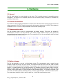
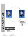
2.3 Communication cable
This four conductor cable is used for communication and battery charging. Three wires are needed for
communication, the fourth one being claimed by the battery charger positive. Charger power ground and
communication ground connect to the same wire. The connections for both the communication cable and wired
buoy are identical and are shown below.
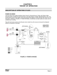
2.4 Battery charger
The PDL was designed for use with an inline battery charger. The communication cable is routed from the
computer, through the charger, and on to the PDL. The charger box has ten LED’s on the face, used to indicate
the amount of current drawn by the PDL battery. The charging current is limited to about an Ampere by internal
circuitry. In normal operation, four or five lights will be on, indicating a current of about 500mA. If the PDL
battery is in good shape, the charging current will drop after a few minutes to perhaps two lights. No lights
indicates a fully charged battery, ten lights indicates a badly discharged battery. The operator is expected to get
in the habit of checking battery performance during connection and subsequent communication with the PDL.
The actual battery voltage is shown in the PDL status box, in the RTMS communications screen.
4
Pdl4_m, SingleChips Inc., Summer 1998
PDL-4 User's Manual
3. Software - RTMS
3.1 Introduction
The computer communicates with the PDL through RTMS (Remote Testing & Monitoring Software). RTMS
provides the following:
{
{
{
{
{
Interface between PDL and user.
Realtime flow calculation and display.
A means of remote PDL calibration.
Data translation.
Screen plotting.
Although RTMS is a DOS program, it gets along well with the Windows environment. If the host machine is
configured correctly and RTMS uses a serial port that no other application is using at the same time, there are no
problems. The program has a minimum three year background in this application, and is currently undergoing
the necessary changes to bring it to the Windows environment. Pending field testing of plungerlift operation this
summer, a beta version should be expected around the end of 1998.
3.1.1 Operation - general
Individual commands are sent to the PDL, which is expected to interpret them and act upon them. Some
commands always generate a response, while others only generate a response if an error occurred in reception.
In this scheme, the computer is always the "master" and the PDL is always the "slave".
All communication between the PDL and RTMS takes place through an augmented implementation of the popular
Xmodem protocol. This assures error-free communication and is particularly important due to the binary
download, where an error can seriously corrupt data.
3.1.2 About Xmodem
The Xmodem file-transfer protocol (also referred to as the Christensen protocol), was introduced to the public
domain by Ward Christensen in 1977. This is a send-and-wait protocol, using a fixed-length data field. It has
been chosen for PDL communications because of its redundant nature. The transmitter assembles the data as
shown above while adding all 128 bytes, and sending this checksum along with it. The receiver does the same
while receiving, and if the checksum values, or the block numbers don't agree, does not acknowledge the block.
The transmitter then resends the block until it is acknowledged. If more than ten rejections occur,
communication stops. This happens in a bi-directional fashion in PDL communications, assuring the best
performance to security ratio.
5
Pdl4_m, SingleChips Inc., Summer 1998
PDL-4 User's Manual
3.2 RTMS files
The program needs and/or creates several files, the extensions of which are significant. All files reside in the
RTMS directory (usually C:\PDL\). These are:
{ RTMS4.INI. This is an ASCII file which must exist, or the program will not start. Contains general
program defaults such as the RTMS files directory, the currently selected site file, baud rate, and
communications port. Here is an example of the contents of a typical file:
[SCi-RTMS]
password=
version=4.20
error=Top
path=c:\pdl
current=J121A1E.TMP
comport=COM2
baudrate=9600
;
;
;
;
;
;
;
;
Heading, significant to the program
Master password
RTMS version
Show errors at top line
Directory
Current temporary site file
Communication port
Baud rate
{ SITENAME.TMP. "SITENAME" is actually replaced by the well or junction name. The contents of the site
file describing W-39-Y-3 is shown below:
[SCi-RTMS Setup]
; Heading, significant to the program
description=PDL-4 Logger #60, Installed 06/04/1998, at W-39-Y-3
; Description
password1=
; User passwords
password2=
TempCo=+65.00, 0.00
; Temperature compensation
siteid=039Y3,36
; Site ID and logger number
powarnum=3902530
; The Well number in Powar
powarname=PM39Y3
; The Junction name in Powar
loggertype=PDL-4
; Logger type
meterrun=2.067
; Size of meter
orifice=1.000
; Size of plate
wet/dry=Wet
; Gas specific gravity approximation
sour/sweet=Sweet
; Gas type
samplerate=30
; The recording interval in minutes
flow=1440
; The flow period in minutes
shutin=30
; The shutin period in minutes
bypass=30
; The bypass period in minutes
diffzmin=+00060
; Differential channel calibration values
diffzmax=+00038
[SCi-RTMS Channels]
Inp,
Temp,
Inp,
U/S,
Inp,
D/S,
Inp,
Diff,
DegF,
PsiG,
PsiG,
PsiD,
; Normal
+00005,
+00864,
+00827,
+00001,
channel calibration
+27952, +0.000,
+28255, +0.000,
+28177, +0.000,
+05003, +0.000,
values
+200.0, Yes
+478.3, Yes
+478.2, Yes
+86.3, Yes
{ SITENAME.001. Created by the program at download time. Contains PDL data in binary form and thus is
not human-readable. If more than one download is made, a second file will be created, and the extension
will be "002". Up to 99 files of the same SITENAME are allowed.
6
Pdl4_m, SingleChips Inc., Summer 1998
PDL-4 User's Manual
3.3 Conversions
When the PDL downloads its memory contents, it purposely does not “translate” its binary files to a
human-readable format. If it did, the download time would be up to 15 times longer, and the resulting files
would be huge. The most efficient way to store PDL information then, is in its native format. This allows
subsequent conversion at any time, and ensures that the original data stays intact.
3.3.1 WinPlot conversion
Winplot is the name given to the file format that PdlPlot can interpret. Once a PDL has been downloaded, the
“Convert to WinPlot” command can be issued to convert the PDL data to WinPlot data. When this is done, the
data can plotted by PdlPlot. The steps required to accomplish this are:
{
{
{
{
Download the unit
Leave the communication screen by pressing ESCAPE
Click on the “Convert to WinPlot” command in the main menu.
Open the generated file in PdlPlot
3.3.2 POWAR conversion
Powar is a special database of daily average production values for each location. The RtmPowar utility reads the
“PDL.ASC” file, crunches the numbers, and produces a file with extension “pw2” or “pw3”. This file is later
imported into the powar database. To start the program click on DOS Programs/RtmPowar menu in PdlPlot. Here
is an example of the typical powar file format:
286d2,,286d2,19971212,,24,,,,,,163.8,106.2,43.0,,0.875,19.2,,,0
286d2,,286d2,19971213,,24,,,,,,171.9,104.5,42.5,,0.875,19.3,,,0
3.3.3 ASCII conversion
Ascii files are used to convert PDL data to Powar data. These are created by RTMS when a PDL to ASCII
translation is requested. To create an Ascii file, repeat as in Winplot above, but click on “Convert to Ascii”
instead. Here is a chunk of a typical file:
[PDLASC_ID]
User=Susan Michelle
Date=1998-02-10
Time=12:15:43
Readings=3940
Interval=30
Powar Number=0000000
Powar Id=0000000
Site Name=286D2
[PDLASC_DATA]
1997-11-20,12:11:39,2.067,0.5000, +46.8,+350.0,+336.0, +13.8,+586.0
1997-11-20,12:41:39,2.067,0.5000, +46.9,+195.9,+159.4, +36.1,+720.7
1997-11-20,13:11:39,2.067,0.5000, +46.9,+185.1,+148.1, +36.8,+708.7
7
Pdl4_m, SingleChips Inc., Summer 1998
PDL-4 User's Manual
4. Calibration
4.1 Introduction
When the PDL “reads” a pressure transmitter, it actually “sees” a number anywhere in the range of -30000 to
+30000. These numbers must be converted to pressure in Psi, temperature in degrees, or any other unit. This is
accomplished by the calibration process. All calibration is done through communications, eliminating the need to
turn trimmers. Included since the PDL-3, is a special temperature compensation scheme, applied to the
differential channel only. Recall that the differential channel is an independent, hardware implemented
differential, and not the arithmetic difference between upstream and downstream.
4.2 Calibration and temperature compensation
An explanation is required of the fields pertinent to calibration. Access to the calibration screen is through the
communication menu. Three fields in the header section must be entered, prior to calibrating anything else.
Identify these in the screen shot below:
{ TempCo in the header section
{ Diff Min and Diff Max in the header section.
{ Imin, Imax, Rmin, Rmax in the channels section.
4.2.1 Temperature compensation
Before commencing the calibration process, do a realtime and mentally record the ambient temperature. Enter
this number in the TempCo field, as shown above. In this example the temperature is 55.00 degrees. The second
number is the drift, either negative or positive, in counts per degree. This number should be very small, usually
less than one. Enter a zero, as shown above. At some later time, the second number can be changed so that the
differential channel is zeroed at some other temperature. Proceed as follows:
{ In the communications menu select “Change..”, then “Change Header”.
{ Go to the TempCo field and enter the temperature you noted above, followed by zero (ex. 55.00,0.00).
{ Press “ESCAPE” a couple of times, and reset the unit as usual.
8
Pdl4_m, SingleChips Inc., Summer 1998
PDL-4 User's Manual
4.2.2 The differential channel
Due to slight differences in component tolerance in the analogue section of the PDL, calibration of the differential
channel is required prior to calibrating the other channels. To calibrate the differential channel proceed as
follows:
{ In the communications menu, select “Calibrate”.
{ Press the “F2” key to edit the header section.
{ Expose both Upstream and Downstream transmitters to the minimum expected pressure range. (This is
usually 0 PsiG).
{ Go to the Diff Min field and press ENTER. The PDL will respond with a value that will replace the previous
value shown in the field.
{ Increase the pressure input to the maximum intended pressure. (usually 500PsiG).
{ Go to the Diff Max field and press ENTER. The PDL will respond with the new value.
{ Press ESCAPE to exit the header section.
{ Press ESCAPE again to return to the communications menu.
{ Select “Erase Memory”, and "Send Setup" in that order. The new values will be sent to the PDL. You now
need to return to the "Calibrate", to complete calibration of the remaining channels.
4.2.3 All other channels
Assuming that the previous step has been completed successfully, proceed as follows to calibrate any other
channel:
{
{
{
{
{
{
{
{
{
Highlight the desired channel and press ENTER.
Apply the minimum intended pressure. (for this example minimum = 0 PsiG)
Go to the Imin field and press ENTER. The PDL will respond with a new value.
Go to the Rmin field and manually enter zero.
Apply the maximum intended pressure. (for this example maximum = 500 PsiG).
Go to the Imax field and press ENTER. The PDL will respond with a new value.
Go to the Rmax field and manually enter 500.
Repeat this procedure for all other channels.
Exit this screen, (after the changes are saved) and select "Send Setup" from the communications menu.
9
Pdl4_m, SingleChips Inc., Summer 1998
PDL-4 User's Manual
5. Intermitter-Plungerlift
5.1 Introduction
Intermitter capability is extended with the inclusion of several new operating modes, in addition to the standard
time based modes. This makes possible seven operating modes, listed below:
{ Datalogger only. This is the default mode after an “Erase Memory” command has been sent to the PDL.
{ Datalogger with ESD (Emergency Shut Down) . This mode is intended for use on wells that may
require it. If the shutdown criteria (low line pressure) is ever encountered, the PDL will switch production
off. The unit will, intentionally, not recover from this condition on its own. This mode may be activated on
flow runs with one or two actuators.
{ Timed Intermitter - two cycle. If the shutin time is set to zero minutes, the unit will not switch to
shutin. In this case the cycle consists of repeated bypass and meter periods.
{ Timed Intermitter - three cycle. This is the expected and rather familiar three cycle intermitter. The
PDL will switch between shutin, bypass and meter indefinitely (or until the battery is low).
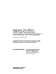
{ Flow based Intermitter - two transmitter. This is the minimum possible configuration for a “smart”,
two transmitter intermitter and the standard timed intermitter. Its drawback is that line pressure (D/S),
can not be determined, since the actuators are after the meter. Its advantage is that a third pressure
transmitter is not required since the U/S pressure is the buildup pressure. This configuration is shown
below:
Bypass Actuator
Flow
PDL
Meter Actuator
{ Flow based Intermitter - three transmitter. In this configuration, a third pressure transmitter is used
to measure the buildup pressure when the flow run is in shutin. Since the line pressure is always known to
the PDL, this is a better configuration than the one described above.
Flow
Bypass Actuator
PDL
Meter Actuator
10
Pdl4_m, SingleChips Inc., Summer 1998
PDL-4 User's Manual
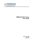
{ Pressure based Plungerlift - three transmitter. This operating mode requires three transmitters and
looks much like the three transmitter intermitter described above. The difference is that the third
transmitter is connected to measure casing pressure, and the switch to shutin condition is dictated by the
pressure difference between casing and tubing. The flow run is shown below:
To Casing
Flow
Bypass Actuator
PDL
Meter Actuator
5.2 “Smart” mode operation
Assuming that the flow run is currently in shutin mode, and the unit has been initialized, operation proceeds as
follows:
{ When the recording interval has expired, the PDL will “wake up”, and read all channels. If the buildup
pressure (intermitter), or casing-to-open pressure (plungerlift), has been reached, it will switch to bypass.
If the “open” condition has not been met, it will remain in shutin and check again at the next recording
time.
{ It will remain in bypass until the bypass time expires, at which time it will switch to meter.
{ The unit will remain in meter mode as long as the flow condition (intermitter), or casing-to-tubing pressure
differential (plungerlift), is met.
{ If the flow condition is not met, it will start the cycle over by switching to shutin.
IMPORTANT: “Smart” modes share the following operating attributes:
v The PDL switches ONLY when it is time to take a reading. If the recording interval is set to 30 minutes,
and it has just switched to meter, it will stay in meter for at least 30 minutes.
v The time spent in bypass must be programmed.
5.2.1 Time modes vs. “smart” modes
There are some operational differences between time and “smart” modes. These are:
{ There is no need to reset the unit when changing the “smart” parameters. In time mode, after setting the
intervals, you must reset the hardware timers by issuing the “Set Unit Time” command.
{ For obvious reasons, the meter and shutin counters are not used in “smart” modes. Set these to 1440
minutes, prior to starting the unit in any “smart” mode.
11
Pdl4_m, SingleChips Inc., Summer 1998
PDL-4 User's Manual
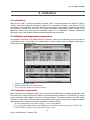
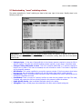
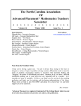
5.3 Understanding “smart” switching criteria
The values responsible for “smart” switching are listed at the lower right of the screen. Identify these in the
following screen shot.
IMPORTANT: The ESD Window and Line Window pressure values, are optional. To disable, set to zero. If
anything but zero values are entered, they will be part of the decision making. Note that zero is the default
value for both.
{ Casing-to-Open. In the case of plungerlift this is the minimum pressure required to cause the PDL to
switch to bypass. This is also the minimum buildup pressure required to open when in intermitter mode.
{ Casing-to-Tubing differential to close. This is the maximum differential (C-T) pressure required to
keep the unit in meter. If this value is exceeded, the unit will switch to shutin. This number is significant
only in plungerlift operation.
{ ESD Window. This number specifies the normal line pressure window. If the line pressure drops below
the lower limit, the unit will switch production off, and will remain shutin until it is reset manually.
{ Flow Window. Used in intermitter mode to specify a range of acceptable flow values. Anything above the
minimum is interpreted as normal.
{ Line Window. There is no point of “opening” the flow run when the line pressure is too high. This value,
if enabled, will prevent the unit from opening unless the line pressure is within the window.
{ Liquid Specific Gravity. Used to calculate the liquid volume in the tubing.
{ Tubing Size. There is a little popup menu attached to this field, used to specify tubing size.
12
Pdl4_m, SingleChips Inc., Summer 1998
PDL-4 User's Manual
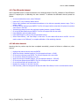
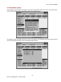
5.4 Intermitter options
The intermitter may be started and stopped in any mode. All intermitter options are shown on the next screen,
and are self-explanatory with the exception perhaps of the statistics screen.
The statistics screen is nothing more than a count of PDL actions. The example screen below, shows that this
PDL has recorded 8415 readings, and has completed 2840 full cycles.
13
Pdl4_m, SingleChips Inc., Summer 1998
PDL-4 User's Manual
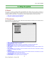
6. Using the system
6.1 General
The program is started by selecting DOS Programs/RTMS4 within PdlPlot. Once the program is started, an
introduction screen is displayed, with the message "Press any key to continue". Respond by hitting any key or
pressing the RIGHT mouse button. The mouse can be used to emulate keyboard keys as shown below:
{ Right button. Emulates pressing the ESCAPE key.
{ Left button. Emulates pressing the ENTER key.
6.3 The main menu
After boat selection, the main menu is shown. Note that choices pertaining to site files are now obsolete, and are
listed here only for compatibility reasons.
{
{
{
{
{
{
{
{
{
{
Select a Site. Allows selection of a new site file.
Create a Site File. Creates a new site file.
Edit a Site File. Allows editing (changing) of parameters in a site file that already exists.
ASCII to Powar. Converts a previously created PDL.ASC file into Powar format.
PDL to ASCII. This option is used or should be used immediately after download. Allows creation of the
PDL.ASC file.
PDL to WinPlot. We had intended to use this command to convert PDL data to Trend data, for plotting
purposes. It is not active in this version.
Quick Plot.
Configure Program. Allows setting-up of general program defaults. Select the communication port, baud
rate, master password, and program main directory.
Communications. Allows access to the communication menu.
Exit SCi-RTMS. Exit the program and return to Windows.
14
Pdl4_m, SingleChips Inc., Summer 1998
PDL-4 User's Manual
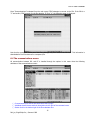
Once “Communications” is selected from the main menu, RTMS attempts to connect to the PDL. If the PDL is a
“3” and earlier, RTMS prompts for site file selection. If it is a “4”, the following screen is displayed:
Note that the system still makes use of site files, although they now reside in the PDL itself. This information is
downloaded to the PC and stored in a temporary file.
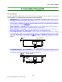
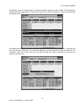
6.4 The communications screen
All communication between PDL and PC is handled through the options in this menu. Note the following
attributes of the communications screen:
{ Communication port and current baud rate at the top right.
{ Individual channel boxes and their descriptions to the right of the command menu.
{ Session clock in the bottom right of the flow calculator box.
15
Pdl4_m, SingleChips Inc., Summer 1998
PDL-4 User's Manual
{ PDL status information at the box at screen bottom.
{ Messages such as "waiting" in the last line.
{ Flow calculator box in the centre. (Only appears during realtime).
6.4.1 New info in RTMS4
Note that several things have been added to the communications screen. These are:
{
{
{
{
Plungerlift and “smart” intermitter criteria at the bottom right.
Estimated remaining recording days, just below the used memory line in status
Time remaining until the next reading, next to the “PDL Status” ilne.
Casing to Tubing difference and Liquid in Tubing (gallons), in the Flow Calculator box
The screen shot below shows a typical PDL realtime screen.
16
Pdl4_m, SingleChips Inc., Summer 1998
PDL-4 User's Manual
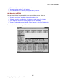
7. Quick Guide
7.1 Introduction
This chapter contains step-by-step instructions on how to do specific things in a question-answer format.
7.1.1 Erase memory - reset
{ How do I reset the PDL and how often should I do it?
It is not necessary to reset the PDL every time you download. What is important to remember is that if you
choose to Erase Memory (reset), you must do some additional things. These are, (make sure to download first):
1. Select "Erase Memory" from the menu and press "Y" when asked "Sure? (Y/N)"
2. Select "Send Setup" from the menu and press "Y" when asked "Sure?(Y/N)"
3. If the PDL is an intermitter, select "Intermitter", then any of the "start" choices
4. Select "Set Unit Time" and click the LEFT mouse button or press "ENTER"
5. Select "Set Unit Id" and click the LEFT mouse button or press "ENTER"
7.1.2 Change plate, meter, recording interval
{ How do I change the plate size in the program?
Select "Change.." then “Change Plate Size” in the Communications menu. Do this after you have physically
changed plate in the camco. A drop list will appear, allowing a choice. Use the cursor keys to see more choices in
the popup menu. A few realtime commands after a plate change will verify that you have actually changed it.
The correct plate size must always be sent to the PDL, as it is recorded and used to calculate flow.
{ How do I change the recording interval?
Repeat the procedure above, but pick “Change Interval” instead. The recording interval must be entered in
integral minutes.
7.1.3 Files
{ What files do I mail to the office?
RTMS names the download file(s) for you. If for example you have just downloaded the logger at J040K1 for the
first time, the data will be in a file called J040K1.001. Subsequent downloads will be named the same, except
that the numbered filename extension will keep increasing. You should mail-in the files with a numbered
extension.
7.1.4 Upgrading the firmware
{ How do I upgrade a PDL-3 into a PDL-4?
The PDL firmware can be upgraded or changed in the field. Starting with firmware version 4000, this process
cannot fail, unless there is a serious hardware problem in the PDL. Upgrading a PDL-3 to a PDL-4 can be tricky,
because a communication problem during the program send can result in trash written into the program chip.
Make sure the communication cable is connected firmly before attempting this. Again: if there is a
communication failure during the upload, PDL removal may be necessary. This situation has been corrected in
the 4xxx series firmware. The necessary steps are:
{ From the communications menu, select “Firmware Upgrade”
{ Select the binary file from the list of choices and press “ENTER” when the message window appears
{ Type “Y” at the (Y/N) prompt and wait for the upload process to end
{ Wait about 10 seconds and reset the unit in the usual manner
{ Make sure that the version number in the status box has changed. If not, repeat the process
17
Pdl4_m, SingleChips Inc., Summer 1998
PDL-4 User's Manual
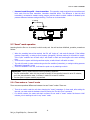
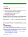
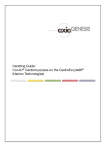
The following screen is produced after the “Firmware Upload” command has been issued. The BIN extension
indicates PDL binary program files. In this example, there are two files in the directory, and the user has selected
the Pdl4001.bin file.
The following screen contains information about the selected binary file to upload (Pdl4001.bin). In this case, the
binary file contains 27,939 bytes, it is 219 xmodem blocks long, and the checksum is 7ab6 in hexadecimal. This
information is also sent to PDL, which uses it to make sure that the process of rewriting its own program is
carried out without errors.
18
Pdl4_m, SingleChips Inc., Summer 1998