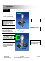
1
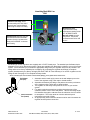
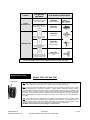
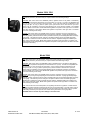
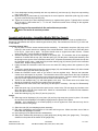
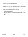
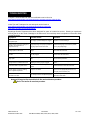
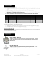
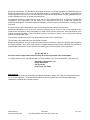
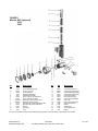
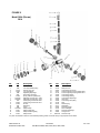
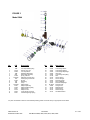
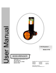
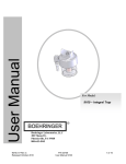
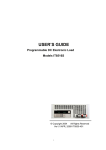
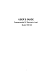
PLATINUM SERIES : User Manual 3800 3804 3840 Higher Performance Suction Regulators With Self Clearing Technology TM And VSS (Validated Sterilization Solution) TM For 3800 Series Suction Regulators: Boehringer Laboratories, LLC 300 Thoms Dr. Phoenixville, PA 19460 800-642-4945 3800 3804 3810 3814 3840 3844 WELCOME Congratulations on your purchase of a Boehringer Suction Regulator. We consider our Suction Regulators to be the best in the world. We are confident they will provide you with reliable, troublefree, safe patient care and low cost of operation. This product is intended for use by individuals properly trained in suctioning procedures by or on the order of a physician. Please read these instructions carefully. Contents Contents ................................................................................................................................... 2 Definition of Terms/ Symbology ............................................................................................... 3 Safety Information .................................................................................................................... 4 Clinical Use............................................................................................................................... 4 Operation .................................................................................................................................. 5 Installation ................................................................................................................................ 6 Mode Selection ......................................................................................................................... 7 Maintenance ............................................................................................................................. 9 Test........................................................................................................................................... 9 Cleaning & Sterilization ............................................................................................................ 10 Disassembly ............................................................................................................................. 10 Assembly .................................................................................................................................. 12 Troubleshooting ........................................................................................................................ 16 Specifications ........................................................................................................................... 17 Warranty ................................................................................................................................... 18 Figure 1, Continuous Regulators (Models 3800, 3810, 3840) ................................................. 19 Figure 2, Intermitting Regulators (Models 3804, 3814) ............................................................ 20 Figure 3, Intermitting Regulator with Line (Model 3844) .......................................................... 21 Appendix A (Processing Recommendations) ........................................................................... 22 3800.019 Rev H Released October 2015 P/N 33784 User Manual 3800, 3804, 3810, 3814, 3840, 3844 2 of 23 Definition of Terms and Symbology VACUUM Air or other gases at a sub atmospheric pressure typically expressed as mmHg or cmH 20. SUCTION A use of vacuum that causes a fluid or solid to be drawn into an interior space or to adhere to a surface because of the difference between the external and internal pressures. Alerts the user to the presence important operating and maintenance instructions in the literature accompanying the device. WARNING Alerts user to actions or conditions that could result in injury to user or patient. CAUTION Alerts user to actions or conditions that can cause damage to the device or may result in substandard performance of the device or system. IMPORTANT Indicates an action that is emphasized to ensure proper operation of equipment. OFF Supply suction is off and patient circuit is vented to atmospheric pressure. REG Supply suction is on and regulated output is controlled to prescribed setting. LINE Supply suction is on and regulation is bypassed to deliver maximum suction to collection circuit. CONTIN Intermitting regulator setting that provides continuous regulated suction to the collection circuit. INT Intermitting regulator setting that allows periodic, automatic application & venting of the collection circuit. Lo Spike: Accuracy of regulation depends primarily on the ability to provide a consistent level of vacuum under changing flow conditions. Involuntary pneumatic biopsy, or tissue damage, can occur when high levels of vacuum are applied to delicate tissue. With a Boehringer regulator, you can depend on very low “spike” compared to our competitor’s models. "Spike" is the variation in indicated suction as flow in the collection circuit changes from an a free flowing condition to an occluded condition. We measure spike as the change in indicated suction from full flow to a no flow condition using a typical collection circuit with a 14 French catheter. To test, set the regulator to 100 mm flowing, and then allow occlude the 14Fr catheter. The change in the indicated suction level is "Spike". Boehringer regulators are checked on the assembly line to meet a specification of less than 10% of the indicated setting, for example 10mmHg spike at a 100 mmHg setting. An evaluation of a regulator’s spike allows one to determine whether the device is truly “regulating”. A safe and reliable regulator should regulate to its set position regardless of variable flow conditions. Validated Sterilization Solution for 270ºF Steam: This steam symbol can be found on all 3800 Boehringer Suction Equipment that has been validated as being able to withstand 270°F pre-vacuum steam autoclave conditions. See 3800.044 for reprocessing guidelines. PARALLAX Inaccuracy caused by observational position of an indicating element (pointer) to a reference element (scale). 3800.019 Rev H Released October 2015 P/N 33784 User Manual 3800, 3804, 3810, 3814, 3840, 3844 3 of 23 Safety Information WARNING! This product is intended for use by or on the order of a physician. It is to be used by individuals who are properly trained in medical suctioning procedures. Please read these instructions carefully. Suction regulators must only be attached to vacuum systems. nitrogen, or oxygen sources. Suction catheters, collection canisters and suction tubing must be carefully evaluated and selected to ensure adequate function for the specific clinical environment and intended field of use. Do not use Boehringer suction regulators in the presence of flammable anesthetics. There have been reports of increased intracranial pressures associated with endotracheal suctioning procedures. "Persistent, increased ICP has been associated with neurological damage and fatalities". (ECRI, Healthcare Product Comparison System (US). Regulators, Suction. Plymouth Meeting (PA), 1999.). Do not attach to compressed air, Always verify regulator operation (Spike, see page 8 for details) before use on a patient. Verify operation by establishing the desired vacuum level with the collection circuit and suction catheter attached to the regulator. Occlude the suction catheter and note that the indicated vacuum does not rise by more than 10% of the original setting. Intermitting Regulators: The automatic return of the patient circuit to atmosphere may not eliminate the need for catheter tip irrigation. As with any automatic system, it is important to monitor the results to be sure that drainage is occurring in a safe efficient manner. The fact that the intermitter is cycling is not an indication that effective drainage is occurring. The Model 3708 Boehringer MRI Suction Regulator is the only MR conditional regulator with FDA 510K approval. The high air flow Boehringer Suction Regulators contraindicate their use with a Vacuum Assisted Delivery (VAD) systems. CLINICAL USE The 3800 Series Continuous Suction Regulators are designed to provide accurate control of wall suction for use in suction therapy procedures in the operating, recovery, intensive care unit, labor and delivery, neonatal, pediatrics, patient bedside, and emergency room. The 3800 Series Intermitting Suction Regulators are designed to provide an intermittent suction source for gastrointestinal drainage procedures. The 3800 series regulators may also be used in procedures that require continuous suction 3800.019 Rev H Released October 2015 P/N 33784 User Manual 3800, 3804, 3810, 3814, 3840, 3844 4 of 23 = Operation FEATURES Continuous Models 3800, 3810, 3840 (Shown with optional trap bottle) Patented Linear Gauge: Allows accurate readings from 180° field of view and never requires calibration. Each range has unique color-coding Adjusting Knob: Extra large, easy grip knob turns COUNTER-CLOCKWISE (direction of arrow) to increase suction setting and CLOCKWISE to decrease suction setting Optional Integral Trap Bottle: Available for the 38XX models. Provides fluid overflow protection utilizing a precision float mechanism Mode Selector Valve: Square knob to easily switch between operating modes DECREASE INCREASE Safety Release: Thumb spring that must be depressed to turn Mode Selector Valve to LINE Intermitting Models 3804, 3814 Patented Linear Gauge: Allows accurate readings from 180° field of view and never requires calibration. Each range has unique color-coding Mode Selector Valve: Large round knob to easily switch between operating modes OFF/ INTERMIT/ CONTIN DECREASE Adjusting Knob: Extra large, easy grip knob turns COUNTER-CLOCKWISE (direction of arrow) to increase suction setting and CLOCKWISE to decrease suction setting INCREASE 3800.019 Rev H Released October 2015 P/N 33784 User Manual 3800, 3804, 3810, 3814, 3840, 3844 5 of 23 Intermitting Model With Line 3844 Patented Linear Gauge: Allows accurate readings from 180° field of view and never requires calibration. Each range has unique color-coding Mode Selector Valve: Large round knob to easily switch between operating modes OFF/ INTERMIT/ CONTIN Must pull out knob to access LINE position. This prevents accidental activation of the LINE function. DECREASE Adjusting Knob: Extra large, easy grip knob turns COUNTER-CLOCKWISE (direction of arrow) to increase suction setting and CLOCKWISE to decrease suction setting INCREASE INSTALLATION All Boehringer suction regulators are supplied with 1/8” NPT female ports. The standard port facilitates simple adaptation to any quick disconnect system. Fittings are available from Boehringer to adapt to your quick connect system. We recommend you purchase the appropriate fittings with your regulator at the time of purchase. The fittings will then be factory installed prior to shipping. By purchasing the regulator and fittings (a complete system) simultaneously, the factory will apply the same TWELVE Year Warranty of our suction regulators to the fittings as well. See page 15 for complete warranty details. In the event that you must assemble or disassemble fittings, please follow these instructions: Wall Adapter Port (rear) 1. Assemble desired male quick connect to the wall adapter port on the back of the regulator using Teflon tape or thread sealant. 2. Assemble the desired inlet fitting to the patient connection port bottom of the regulator using Teflon tape or thread sealant. 3. The regulator is now ready to be placed in service on your suction system. 4. For gastric suctioning procedures, position the patient port of the collection canister 12-18” above the patient. This will encourage slight fluid backflow through the catheter when the collection circuit is vented to atmosphere. This action tends to clear the catheter tip and Patient Connection maximize the removal of fluids. Port (bottom) 5. An appropriately sized collection canister must be used in between the regulator and the patient connection. 3800.019 Rev H Released October 2015 P/N 33784 User Manual 3800, 3804, 3810, 3814, 3840, 3844 6 of 23 Configuration requirement Location Patient Connection Port Order Number and Description Model 2469 Suction tubing attached directly to the suction regulator High Flow Bubble Barb Suction regulator attached to collection canister, roll stand or trap bottle DISS Body Adapter Model 1487 Model 1492 Vacuum outlet requires a 90° twist to release the regulator Diamond Ohio Model 1493 Wall Adapter Port Vacuum outlet has a button to release the regulator Chemetron (NCG) Rectangular Adapter Model 1504 The adapter screws onto the outlet and then is unscrewed to remove (approximately 3 turns) DISS Hand-Tight Nut and Gland For special adapter requirements, please contact us at 800-642-4945. MODE SELECTION Models 3800, 3810 and 3840 Safety Release OFF: With control valve in the OFF position, suction is off and the collection circuit is returned to atmospheric pressure by an internal vent port, a special feature of the Boehringer design. REG: With control valve in the REG position, wall suction may be controlled to a specific level by turning the large adjusting knob in the direction indicated. A spring opposed diaphragm assembly precisely controls the level of suction provided at the lower port of the Regulator within the range of the gauge. This assembly "senses" changes in the patient collection circuit and makes appropriate adjustments to maintain the suction level that has been selected. Regulated settings are verified by the large, easy to read gauge. Model 7800 regulators incorporate a safe upper limit so they will not deliver any more than 230mmHg in this setting. LINE: With control valve in the LINE position, the regulating mechanism is bypassed. Full wall suction is applied to the patient collection system through the lower port of the Regulator. The LINE suction mode is engaged by depressing the safety spring release and rotating the control valve to the line position. LINE setting is verified by the exposure of the "LINE" warning at the bottom of the gauge label. CAUTION! Full line suction may cause damage to sensitive tissue. 3800.019 Rev H Released October 2015 P/N 33784 User Manual 3800, 3804, 3810, 3814, 3840, 3844 7 of 23 Models 3804, 3814 OFF: With control valve in the OFF position, suction is off and the collection circuit is returned to atmospheric pressure by an internal vent port, a special feature of the Boehringer design. INTERMIT: With control valve in the INTERMIT position, regulated suction to the patient is intermittently turned on and off (vented to atmosphere) at a nominal ratio of 2:1 (on:off). The ratio is not adjustable and the cycle time (‘on’ plus ‘off’ time) is set at the factory. If the cycle time needs to be adjusted, turn the timing screw (No. 31 on fig. 2) CCW to speed up the cycle time and CW to slow down the cycle time. Suction may be controlled by turning the large adjusting knob in the direction indicated. See CONTIN below for details of the suction control. Model 3804 regulators incorporate a safe upper limit to not deliver more than 230mmHg in this setting. Model 3814 regulators incorporate a safe upper limit to not deliver more than 115mmHg in this setting. CONTIN: With control valve in the CONTIN position, suction is continuous and may be controlled to a specific level by turning the large adjusting knob in the direction indicated. A spring opposed diaphragm assembly precisely controls the level of suction provided at the lower port of the Regulator within the range of the gauge. This assembly "senses" changes in the patient collection circuit and makes appropriate adjustments to maintain the suction level that has been selected. Regulated settings are verified by the large, easy to read linear gauge. Model 3804 regulators incorporate a safe upper limit to not deliver more than 230mmHg in this setting. Model 3814 regulators incorporate a safe upper limit to not deliver more than 115mmHg in this setting. Model 3844 OFF: With control valve in the OFF position, suction is off and the collection circuit is returned to atmospheric pressure by an internal vent port, a special feature of the Boehringer design. INTERMIT: With control valve in the INTERMIT position, regulated suction to the patient is intermittently turned on and off (vented to atmosphere) at a nominal ratio of 2:1 (on:off). The ratio is not adjustable and the cycle time (‘on’ plus ‘off’ time) is set at the factory. If the cycle time needs to be adjusted, turn the timing screw (No. 31 on fig. 2) CCW to speed up the cycle time and CW to slow down the cycle time. Suction may be controlled by turning the large adjusting knob in the direction indicated. See CONTIN below for details of the suction control. Model 3844 regulators incorporate a safe upper limit to not deliver more than 230mmHg in this setting. CONTIN: With control valve in the CONTIN position, suction is continuous and may be controlled to a specific level by turning the large adjusting knob in the direction indicated. A spring opposed diaphragm assembly precisely controls the level of suction provided at the lower port of the Regulator within the range of the gauge. This assembly "senses" changes in the patient collection circuit and makes appropriate adjustments to maintain the suction level that has been selected. Regulated settings are verified by the large, easy to read linear gauge. Model 3844 regulators incorporate a safe upper limit to not deliver more than 230mmHg in this setting. LINE: With control valve in the LINE position, the regulating mechanism is bypassed. Full wall suction is applied to the patient collection system through the lower port of the Regulator. The LINE suction mode is engaged pulling the control knob out (direction of arrow) and rotating the control valve to the line position. LINE setting is verified by the exposure of the "LINE" warning at the bottom of the gauge label. CAUTION! Full line suction may cause damage to sensitive tissue. 3800.019 Rev H Released October 2015 P/N 33784 User Manual 3800, 3804, 3810, 3814, 3840, 3844 8 of 23 MAINTENANCE Your Boehringer Regulators have been designed to provide years of trouble free operation. Most service activity is the result of aspiration of bodily fluids or other foreign materials into the regulator. Your 3800 series regulator is equipped with patented Air Curtain Protection to provide isolation of critical control elements from the inadvertent intrusion of foreign contaminants. The routine use of an appropriate collection canister greatly reduces needed service. To determine your cleaning/maintenance schedule: Periodically inspect the overall condition of the instrument. Test the gauge accuracy and check the instrument function as described under ‘Test’. Simply clearing the small orifices in the gauge view tube and the regulator body can remedy many performance conditions (see troubleshooting). Return to service if the instrument performs appropriately per the ‘Test’ requirements. Based on data from your periodic inspections, determine a cleaning/maintenance schedule appropriate for the operational conditions of your facility. Clean, inspect, lubricate, and test based on your schedule and according to the Instrument Cleaning, Instrument Lubrication and ‘Test’ section outlined below. TEST 1. With the control valve in the REG or CONTIN position and a collection system attached with a 14 Fr. catheter, regulator should control vacuum from 10-100% of full scale (FS). 2. With the control valve in the REG or CONTIN position and housing turned all the way off, with suction port occluded, gauge should read zero. 3. With the control valve in the REG or CONTIN, adjust regulator to the middle of the scale and occlude the catheter. Gauge movement should be less than 10% of the setting. This measurement is called spike. 4. The gauge should be accurate to 5% of full scale (FS) (±5mmHg for 3810 & 3814; ±10mmHg for 3800, 3804 & 3844; ±38mmHg for 3840) for any measurement within the range of the scale. If this is not the case, please return the gauge to the manufacturer for repair/replacement. CAUTION: Inaccurate gauge calibration may lead to a high suction condition applied to the patient. 5. With the control valve in the OFF position, suction should be at atmospheric and gauge should read zero. With suction port occluded, gauge should read zero. 6. With the control valve in the REG or CONTIN position, with an appropriate collection system attached (>800cc capacity) set the Regulator to the middle of the scale and turn control valve to OFF, then back to REG or CONTIN. Gauge indicator should not travel more than 20% past the set point before settling at the desired level. 7. With the intermitter control valve in the INTERMIT position, the factory calibrated cycle will be 4-5 seconds OFF, with an ON time being a multiple of 1.6 to 3 times the OFF time. Adjust the timing screw counterclockwise to speed up the cycle time and counter clockwise to slow down the cycle time. 8. A final, important step in instrument maintenance is the identification of the instrument. This confirms that a qualified individual performed service to accepted procedures and approved master gauges. An ID tag should accompany the instrument, which indicates (as a minimum): date of service, individual performing the service and the date of next service. CAUTION: Have the regulator factory serviced if not performing to specifications. See Warranty and Repair on p.15 for details on getting your instrument factory serviced. 3800.019 Rev H Released October 2015 P/N 33784 User Manual 3800, 3804, 3810, 3814, 3840, 3844 9 of 23 Cleaning & Sterilization Please refer to Boehringer document 3800.044, Boehringer Platinum Series Suction Regulator Recommendations for Cleaning and Reprocessing for guidance. This information is available online at www.boehringerlabs.com, or toll-free at 1-800-642-4945. DISASSEMBLY Continuous Models 3800, 3810, 3840 (See Fig. 1) Regulator: 1. Back out lock screw (8) on housing assembly (7) with 1/16 hex wrench. 2. Unscrew diaphragm housing (7) from regulator body. 3. Remove valve retaining screw (19) and washer (20) with 5/32 hex wrench. Pull out control valve. The control valve is factory matched to the particular regulator body. If multiple units are disassembled, take care to keep like parts mated. 4. In the unlikely event suctioned material should enter the regulator diaphragm housing, it will be necessary to disassemble and scrub the unit as follows: a. Remove quad ring (10) and Shroud (9) by hand, then remove the lens cap retaining ring (1) and lens cap (2) and lens cap backer (3). b. Push out diaphragm (3) by pressing on piston/stem assembly (5). c. Remove piston/stem assembly (5) and spring (6). Gauge: 5. Remove the retaining ring (18) using retaining ring pliers. From the front of the gauge, use thumb to rotate and loosen view tube (17). Then remove view tube-piston-diaphragm assembly (17,16,15,14). 6. Remove the lower lip of the diaphragm from outside of the view tube, and slide out the diaphragmpiston assembly. 7. Remove the upper diaphragm lip from the top of piston, and slide diaphragm off piston. 8. Remove spring (13). NOTE: It is not necessary to remove the gauge body from the regulator body prior to cleaning. IMPORTANT: Always clean the unit prior to assembly. Disassembly – Intermitting Models 3804, 3814 (See Fig. 2) Regulator: 1. Back out lock screw (8) on housing assembly (7) with 1/16 hex wrench. 2. Unscrew housing assembly (6) from regulator body. 3. Remove the dashpot cover (16) and filter (15). Remove the retaining ring (14). 4. Unscrew the cap (31), spring (27), piston (28) and diaphragm (29). Remove timing screw (30). Note the orientation of the diaphragm for reassembly. 5. Push the spool out and inspect for wear and corrosion. Inspect the ring (13) on the spool for misalignment and/or damage. The ring will have a small cut in it. This spool is factory matched to its mating control valve. If disassembling multiple units, take care to ensure like parts remain mated for reassembly. Note: The ball spring and screw shown on the inside of the movable spool valve should only be disassembled if they are grossly contaminated. If the relief valve screw is removed, note its position and number of threads of insertion prior to removal and thread the screw back to the same position during reassembly. This sets the intermediate pressure that determines the timing of the spool valve. 3800.019 Rev H Released October 2015 P/N 33784 User Manual 3800, 3804, 3810, 3814, 3840, 3844 10 of 23 6. Unscrew the dashpot body (12) and pull the intermitter control valve out of the regulator body. Remove the detent ball (26) and spring (25) from the regulator body. The regulator control valve is factory matched to its regulator body. If disassembling multiple units, take care to ensure like parts remain mated for reassembly. 7. Replace filter (24) in the regulator body if damaged or clogged. Remove by pressing out from bottom side or prying out with a small tool. 8. In the unlikely event suctioned material should enter the housing assembly (7), it will be necessary to disassemble and scrub the unit as follows: a. Remove quad ring (10) and Shroud (9) by hand, then remove the lens cap retaining ring (1), lens cap (2) and lens cap backer(3). b. Push out diaphragm (4) by pressing on piston/stem assembly (5). c. Remove piston/stem assembly (5) and spring (6). Gauge: 9. Remove the retaining ring (23) using retaining ring pliers. From the front of the gauge, use thumb to rotate and loosen view tube (22). Then remove view tube-piston-diaphragm assembly (19, 20, 21, 22). 10. Remove the lower lip of the diaphragm from outside of the view tube, and slide out the diaphragmpiston assembly. 11. Remove the upper diaphragm lip from the top of piston, and slide diaphragm off piston. 12. Remove spring (18). NOTE: It is not necessary to remove the gauge body from the regulator body prior to cleaning. IMPORTANT: Always clean the unit prior to assembly. Disassembly – Intermitting Models 3844 (See Fig. 3) Regulator: 9. Back out lock screw (8) on housing assembly (7) with 1/16 hex wrench. 10. Unscrew housing assembly (7) from regulator body. 11. Remove the dashpot cover (16) and filter (15). Remove the retaining ring (14). 12. Remove the intermitter cap retaining ring (32) and pull out the cap (30), spring (27), piston (28) and diaphragm (29). Remove timing screw (31). Note the orientation of the diaphragm for reassembly. 13. Push the spool out and inspect for wear and corrosion. Inspect the ring (13) on the spool for misalignment and/or damage. The ring will have a small cut in it. This spool is factory matched to its mating control valve. If disassembling multiple units, take care to ensure like parts remain mated for reassembly. Note: The ball spring and screw shown on the inside of the movable spool valve should only be disassembled if they are grossly contaminated. If the relief valve screw is removed, note its position and number of threads of insertion prior to removal and thread the screw back to the same position during reassembly. This sets the intermediate pressure that determines the timing of the spool valve. 14. Unscrew the dashpot body (12) and pull the intermitter control valve out of the regulator body. Remove the detent ball (26) and spring (25) from the regulator body. The regulator control valve is factory matched to its regulator body. If disassembling multiple units, take care to ensure like parts remain mated for reassembly. 15. Replace filter (24) in the regulator body if damaged or clogged. Remove by pressing out from bottom side or prying out with a small tool. 16. In the unlikely event suctioned material should enter the housing assembly (7), it will be necessary to disassemble and scrub the unit as follows: a. Remove quad ring (10) and Shroud (9) by hand, then remove the lens cap retaining ring (1), lens cap (2) and lens cap backer(3). b. Push out diaphragm (4) by pressing on piston/stem assembly (5). c. Remove piston/stem assembly (5) and spring (6). Gauge: 3800.019 Rev H Released October 2015 P/N 33784 User Manual 3800, 3804, 3810, 3814, 3840, 3844 11 of 23 13. Remove the retaining ring (23) using retaining ring pliers. From the front of the gauge, use thumb to rotate and loosen view tube (22). Then remove view tube-piston-diaphragm assembly (19, 20, 21, 22). 14. Remove the lower lip of the diaphragm from outside of the view tube, and slide out the diaphragmpiston assembly. 15. Remove the upper diaphragm lip from the top of piston, and slide diaphragm off piston. 16. Remove spring (18). NOTE: It is not necessary to remove the gauge body from the regulator body prior to cleaning. IMPORTANT: Always clean the unit prior to assembly. ASSEMBLY Assembly and Lubrication – Continuous Models 3800, 3810, 3840 (See Figure 1) After disassembling and cleaning the instrument, assemble and lubricate as follows. Parts are available from Boehringer Laboratories, LLC and may be ordered by part number (P/N). Part numbers are found in figure 1 at the end of this manual. Regulator: 1. Lubricate control valve (OFF, REG, LINE) over entire mating surface with synthetic lubricant (P/N 1895). 2. Rotate valve as you insert it into the body. Remove the valve and inspect for dry areas. The valve must have a thin layer of lubricant over its entire diameter without excess in the cross ports. 3. Lubricate the threaded sleeve in diaphragm housing (7) and U-cup (11) with a light coat of synthetic lubricant (P/N 1895). 4. Assemble diaphragm housing in reverse order of disassembly. Do not lubricate the stainless steel shaft of the piston/stem assembly (5) or the inside of the threaded sleeve (7). 5. Inspect quad ring seal (10) for cuts or wear. Replace if needed. DISASSEMBLY 6. Assemble unit in reverse order of disassembly. Place spring (6) on piston/stem assembly (5) and then insert through diaphragm housing assembly (7). 7. Install diaphragm (4) into housing with the lip going into groove of housing. 8. Cover diaphragm housing assembly with lens cap backer (3) and lens cap (2). Snap lens cap retaining ring (1) into groove. 9. Install shroud (9) to piston stem (5) it will snap into its correct position. Assemble quad ring (10) to stem (5), then screw the housing into body fully. 10. Tighten lock screw (8) to retain diaphragm housing on regulator body groove. Typically this is screwed all of the way in, and backed out ½ - ¾ of a turn. Ensure this screw does not drag as the regulator setting is adjusted. 11. Insert the control valve and position the valve retaining washer (20) before securing it with the valve retaining screw (19) Gauge: 12. Slide large end of diaphragm (16) over piston (14) until top ring snaps into groove in piston. Be certain the top bead of the diaphragm is completely engaged into the groove of the piston. CAUTION: If the diaphragm is not seated properly it will rub against the view tube and may lead to premature failure of the gauge. 13. 14. 15. 16. 17. 18. Slide view tube (17) over diaphragm-piston assembly. Roll edge of diaphragm around bottom of view tube and into groove. Make sure there are no folds or twists and that diaphragm is smooth. Insert spring (13) into piston/view tube subassembly. Slide piston subassembly with spring up (and gauge body facing down) into gauge body. The spring should sit in the pocket at the bottom of the gauge body. Press until view tube assembly rests on shoulder in gauge body. Assemble retaining ring (18) into groove in gauge body. IMPORTANT: Always clean the unit prior to assembly. 3800.019 Rev H Released October 2015 P/N 33784 User Manual 3800, 3804, 3810, 3814, 3840, 3844 12 of 23 Assembly and Lubrication – Intermitting Models 3804 and 3814 (See Figure 2) After disassembling and cleaning the instrument, assemble and lubricate as follows. Parts are available from Boehringer Laboratories and may be ordered by part number (P/N). Part numbers are found in Fig. 2 at the end of this manual. Intermitter Control Valve 1. Dry all parts to remove excess moisture before assembly. If Autoclaved, the piston (28) may not fit properly in the control valve due to swelling of the outside diameter. If this is the case, allow the piston to air dry for 1 hour and try again. The piston should return to original size within 6 hours. Heated drying (max 270°F) can accelerate the drying process. 2. Seat the diaphragm (29) around the outside of piston (28). The smoother side of the diaphragm should be in contact with the cap (31). Seat the spring (27) into the piston. Holding this assembly, seat the spring into the groove of the intermitter control valve, compress the assembly and screw the cap onto the intermitter control valve. Fully seat the cap against the intermitter control valve. Replace timing screw (30). 3. Lightly lubricate the intermitter control valve over the entire OD mating surface with synthetic oil (P/N 1895). 4. Rotate the intermitter control valve as you insert it into the regulator body. Remove the intermitter control valve and inspect for dry areas. The intermitter control valve must have a thin layer of lubricant over its entire diameter without excess in the cross-ports and grooves. Place the detent spring (25) and ball (26) into the regulator body and reinsert the control valve into the body. 5. Thread on the dashpot body (12) and hand tighten to the stop. The control valve must rotate freely through its 3 positions. 6. Reinstall the relief valve screw, ball, and spring into the spool if necessary. See step 5 of Disassembly above. 7. Install the spool ring (13) and insert the spool into the control valve. DO not apply any lubricant to the OD of the spool or the ID of the control valve. Check for a smooth fit/feel. It is normal to feel resistance when near the full insertion. 8. Install the retaining ring (14), filter (15) and vinyl cap (16) Gauge: 9. Slide large end of diaphragm (21) over piston (19) until top ring snaps into groove in piston. Be certain the top bead of the diaphragm is completely engaged into the groove of the piston. CAUTION: If the diaphragm is not seated properly it will rub against the view tube and may lead to premature failure of the gauge. 10. Slide view tube (22) over diaphragm-piston assembly. 11. Roll edge of diaphragm around bottom of view tube and into groove. Make sure there are no folds or twists and that diaphragm is smooth. 12. Insert spring (18) into piston/view tube subassembly. 13. Slide piston subassembly with spring up (and gauge body facing down) into gauge body. The spring should sit in the pocket at the bottom of the gauge body. 14. Press until view tube assembly rests on shoulder in gauge body. 15. Assemble retaining ring (23) into groove in gauge body. Regulator: 16. Lubricate the threaded sleeve in diaphragm housing (7) and U-cup (11) with a light coat of synthetic lubricant (P/N 1895). 17. Assemble diaphragm housing in reverse order of disassembly. Do not lubricate the stainless steel shaft of the piston/stem assembly (5) or the inside of the threaded sleeve (7). 18. Inspect quad ring seal (10) for cuts or wear. Replace if needed. 19. Assemble unit in reverse order of disassembly. Place spring (6) on piston/stem assembly (5) and then insert through diaphragm housing assembly (7).\ 20. Install diaphragm (4) into housing with the lip going into groove of housing. 3800.019 Rev H Released October 2015 P/N 33784 User Manual 3800, 3804, 3810, 3814, 3840, 3844 13 of 23 21. Cover diaphragm housing assembly with lens cap backer (3) and lens cap (2). Snap lens cap retaining ring (1) into groove. 22. Install shroud (9) to piston stem (4) it will snap into its correct position. Assemble quad ring (10) to stem (5), then screw the housing into body fully. 23. Tighten lock screw (8) to retain diaphragm housing on regulator body groove. Typically this is screwed all of the way in, and backed out ½ - ¾ of a turn. Ensure this screw does not drag as the regulator setting is adjusted. IMPORTANT! Always test the reassembled unit after each maintenance procedure. See the Test section for exact test procedure. Assembly and Lubrication – Intermitting Models 3844 (See Figure 3) After disassembling and cleaning the instrument, assemble and lubricate as follows. Parts are available from Boehringer Laboratories and may be ordered by part number (P/N). Part numbers are found in Fig. 3 at the end of this manual. Intermitter Control Valve 1. Dry all parts to remove excess moisture before assembly. If Autoclaved, the piston (28) may not fit properly in the control valve due to swelling of the outside diameter. If this is the case, allow the piston to air dry for 1 hour and try again. The piston should return to original size within 6 hours. Heated drying (max 270°F) can accelerate the drying process. 2. Seat the diaphragm (29) around the outside of the piston (28). The smoother side of the diaphragm should be in contact with the cap (30). Seat the spring (27) into the piston. Holding this assembly, seat the spring into the groove of the intermitter control valve, compress the assembly and press the cap into the intermitter control valve. Install and fully seat the retaining ring (32) into the groove in the intermitter control valve. Replace timing screw (31). 3. Lightly lubricate the intermitter control valve over the entire OD mating surface with synthetic oil (P/N 1895). 4. If removed, reinstall the detent spring (33), detent plunger (34), and threaded retainer (35). Also reinstall the tension spring (25) and tension plunger (26). 5. Rotate the intermitter control valve as you insert it into the regulator body. Remove the intermitter control valve and inspect for dry areas. The intermitter control valve must have a thin layer of lubricant over its entire diameter without excess in the cross-ports and grooves. Place the detent spring (24) and ball (25) into the regulator body and reinsert the control valve into the body. 6. Thread on the dashpot body (11) and hand tighten to the stop. The control valve must rotate freely through its 3 positions, and pull out to rotate into the line position. 7. Reinstall the relief valve screw, ball, and spring into the spool if necessary. See step 5 of Disassembly above. 8. Install the spool ring (13) and insert the spool into the control valve. DO not apply any lubricant to the OD of the spool or the ID of the control valve. Check for a smooth fit/feel. It is normal to feel resistance when near the full insertion. 9. Install the retaining ring (14), filter (15) and vinyl cap (16) Gauge: 10. Slide large end of diaphragm (21) over piston (19) until top ring snaps into groove in piston. Be certain the top bead of the diaphragm is completely engaged into the groove of the piston. CAUTION: If the diaphragm is not seated properly it will rub against the view tube and may lead to premature failure of the gauge. 11. Slide view tube (22) over diaphragm-piston assembly. 12. Roll edge of diaphragm around bottom of view tube and into groove. Make sure there are no folds or twists and that diaphragm is smooth. 13. Insert spring (18) into piston/view tube subassembly. 14. Slide piston subassembly with spring up (and gauge body facing down) into gauge body. The spring should sit in the pocket at the bottom of the gauge body. 3800.019 Rev H Released October 2015 P/N 33784 User Manual 3800, 3804, 3810, 3814, 3840, 3844 14 of 23 15. Press until view tube assembly rests on shoulder in gauge body. 16. Assemble retaining ring (23) into groove in gauge body. Regulator: 17. Lubricate the threaded sleeve in diaphragm housing (7) and U-cup (11) with a light coat of synthetic lubricant (P/N 1895). 18. Assemble diaphragm housing in reverse order of disassembly. Do not lubricate the stainless steel shaft of the piston/stem assembly (5) or the inside of the threaded sleeve (7). 19. Inspect quad ring seal (10) for cuts or wear. Replace if needed. 20. Assemble unit in reverse order of disassembly. Place spring (6) on piston/stem assembly (5) and then insert through diaphragm housing assembly (7). 21. Install diaphragm (4) into housing with the lip going into groove of housing. 22. Cover diaphragm housing assembly with lens cap backer (3) and lens cap (2). Snap lens cap retaining ring (1) into groove. 23. Install shroud (9) to piston stem (5) it will snap into its correct position. Assemble quad ring (10) to stem (5), then screw the housing into body fully. 24. Tighten lock screw (8) to retain diaphragm housing on regulator body groove. Typically this is screwed all of the way in, and backed out ½ - ¾ of a turn. Ensure this screw does not drag as the regulator setting is adjusted. IMPORTANT! Always test the reassembled unit after each maintenance procedure. See the Test section for exact test procedure. 3800.019 Rev H Released October 2015 P/N 33784 User Manual 3800, 3804, 3810, 3814, 3840, 3844 15 of 23 TROUBLESHOOTING Complete Technical Manuals and Service Bulletins can be found at http://www.boehringerlabs.com/support/suction-regulator-technical-manuals.php Video Tips and Techniques for use and repair can be found at: http://www.boehringerlabs.com/support/video/product-videos.php http://www.youtube.com/boehringerlabsllc Boehringer Suction Regulators have been designed for years of trouble-free service. Should you experience difficulty that is not the result of damage to the instrument, the most likely cause is aspiration of dirt and/or fluids into the Regulator. Symptom Probable Cause Solution DISASSEMBLY Instrument fails to provide suction at the patient port. The supply or patient fittings are clogged Replace or clean the fittings Gauge doesn't respond to changes in suction (via control valve or adjustment knob) Gauge diaphragm is improperly sealed on the gauge piston and/or view tube Disassemble gauge and check the position of the gauge diaphragm. Gauge piston is discolored Material has entered the inside of the gauge Instrument is contaminated. Disassemble and clean the instrument. Gauge responds slowly to changes in suction The small hole in the top of the View Tube may be plugged. Using a small diameter probe, pierce the hole to clear the obstruction. Instrument will not shut off or exhibits high spike Dried fluids may have cut the quad ring seal. Replace the quad ring (5) and Test the unit as per above procedure. Instrument exhibits high droop or gauge flutters on dead ended circuit. The small brass orifice inside of the diaphragm housing may be clogged. Clear any obstruction using a small diameter probe. Instrument fails to regulate suction Piston/Stem surface is binding with foreign matter Disassemble and clean the instrument. Erratic gauge movement resulting from regulator adjustment Gauge is not sealed Make sure retaining ring (17) is seated in groove on the gauge body and there is no end play in the view tube (19). The unit will not intermit, or intermits too fast or too slow The Timing Screw is not adjusted properly Adjust timing screw (31) CCW to speed up and CW to slow down. IMPORTANT! Always test the reassembled unit after each maintenance procedure. See the Test section for exact test procedure. 3800.019 Rev H Released October 2015 P/N 33784 User Manual 3800, 3804, 3810, 3814, 3840, 3844 16 of 23 SPECIFICATIONS Inlet and outlet fittings: 1/8 NPT Gauge accuracy ANSI Class B, ±5% FS (±5mmHg 3810 & 3814; ±10mm Hg 3800&3804 ; ±38mm Hg 3840) Regulation Accuracy: ±10% FS from full flow to zero flow with 14 FR catheter attached. Leak rate in OFF position: less than 1 cc/min Free Air Flow: Greater than 38 LPM with regulator set to 100 mmHg at standard JCAHO supply (305mmHg @ 180 SCFH) and a typical collection circuit. Materials: polycarbonate, hard-anodized aluminum, stainless steel, Buna rubber, acetal copolymer. Model Regulation Range User Selectable Modes 3800 20-200 mm Hg Off, Regulated Control, Line (source vacuum) 1.35 5¾ x 2½ x 4 3804 20-200 mm Hg Off, Intermitting, Continuous 1.64 5¾ x 4 x 4 Off, Regulated Control 1.35 5¾ x 2½ x 4 3810 10-115mm Hg DISASSEMBLY Wt. (lb)* H x W x D (in) 3814 10-115mm Hg Off, Intermitting, Continuous 1.64 5¾ x 4 x 4 3840 76-760 mm Hg Off, Regulated Control, Line (source vacuum) 1.35 5¾ x 2½ x 4 3844 20-200 mm Hg Off, Intermitting, Continuous, Line 1.64 5¾ x 4⅛ x 4 *Regulator weights are without fittings. Intermitting Specifications - Model 3804, 3814 & 3844 Intermit Cycle: User adjustable, factory adjusted to a nominal 8:4 secs (On:Off) @ 500 mmHg supply. Intermit Ratio: Fixed, nominal 2:1 On:Off @ 500 mmHg supply Operating and Storage Limits We recommend that Boehringer Suction regulators be operated and stored at controlled conditions that typically reflect the medical facility environment. ACCESSORIES Integral Trap Bottle – Model 9100 This device will protect your regulators and suction system from fluid overflow. The bottle provides a 60 ml backup overflow volume with shut-off capability provided by a precision float mechanism. Warranty and Repair Boehringer Laboratories, LLC guarantees all 3800 Series LONG LIFE Suction Regulators for Inline Filter – Model 7791 TWELVE years. Boehringer Laboratories, LLC will also warrant all fittings purchased from and This device will protect your regulators and suction system from fluid overflow. It is a installed by Boehringer Laboratories, LLC for the same warranty period as the suction regulator hydrophobic, high flow, 1.0 micron filter. The filter goes in the patient circuit between the DISASSEMBLY on which they were originally installed. waste canister and the regulator. 3800.019 Rev H Released October 2015 P/N 33784 User Manual 3800, 3804, 3810, 3814, 3840, 3844 17 of 23 Boehringer Laboratories, LLC warrants to the original purchaser, new suction regulators purchased directly from Boehringer Laboratories, LLC or from an authorized dealer or representative. This warranty guarantees the suction regulators to be free from functional defects in materials and workmanship. We also guarantee that our suction regulators will meet our published specifications. All regulators returned for repair shall be clean and free from contamination prior to shipment to Boehringer Laboratories. This requirement is for the safety of our employees as well as to comply with Federal Law prohibiting the shipment of unmarked biohazard materials. If units are returned contaminated, a cleaning charge may result. A service charge may be assessed on any unit returned that shows evidence of gross abuse. Boehringer Laboratories, LLC is the only authorized warranty service center for our suction regulators. Any repair service requesting a return authorization for repair will be asked to provide the name and location of the original equipment purchaser. If this information cannot be provided, the repair is not covered under warranty and will be a chargeable repair. This warranty excludes acts of God, fire, flood and acts of war, terror or insurrection. This warranty is not transferable from the original purchaser. Boehringer Laboratories’ sole and exclusive remedy under this warranty is limited to repairing and/or replacing the suction regulator. There are no other express or implied warranties beyond these warranties set forth above. At Boehringer Laboratories, we are committed to lowering your suction regulator costs of operation! ▼▼▼▼▼▼▼▼▼ All repairs will be shipped back within five days of receipt of purchase order authorization. For quality factory service, call 800-642-4945 or 610-278-0900 for your return authorization. Ship returns to: Boehringer Laboratories, LLC Repair Department 300 Thoms Dr. Phoenixville, PA 19460 New Products We are continually striving to reach higher and higher standards of quality. We value your comments and input on our suction regulators. If you are pleased with this instrument, please find out more about Boehringer Laboratories' complete line of suction controls. 3800.019 Rev H Released October 2015 P/N 33784 User Manual 3800, 3804, 3810, 3814, 3840, 3844 18 of 23 FIGURE 1 Models 3800 (pictured) 3810 3840 No. P/N 1 2 3 4 5 6 6 7 7 8 8 9 10 11 1465 33916 33909 1466 2297 33768 33797 33763AS 33902AS 1479 33582 33764 1461 1484 Description Lens Cap Retaining Ring Generic Lens Cap Lens Cap Backer Regulating Diaphragm Piston/Stem Assembly Spring, 200 mm Hg (3800/3810) Spring, 760 mm Hg (3840) Diaphragm Housing (3800, 3840) Diaphragm Housing (3810) Dog Point Set Screw, Model 3800, 3840 Dog Point Set Screw, Model 3810 Shroud Quad Ring U-cup No. P/N 12 13 13 13 14 15 16 17 18 19 20 21 22 23 33043 33906 33041 33115 33036 33610 33042 33040 33038 1468 1454 1462 1462 353 Description Linear Gauge Fastener 0-100mmHg Spring (3810) 0-200mmHg Spring (3800) 0-760mmHg Spring (3840) Linear Gauge Piston Linear Gauge O-Ring Linear Gauge Diaphragm View Tube Linear Gauge Snap Ring Control Valve Screw Washer Thumbspring Thumbspring screw O-Ring For parts not available for sale from this breakaway drawing please consult the factory for appropriate service details. 3800.019 Rev H Released October 2015 P/N 33784 User Manual 3800, 3804, 3810, 3814, 3840, 3844 19 of 23 FIGURE 2 Model 3804 (Shown) 3814 No. P/N 1 2 3 4 5 6 7 7 8 8 9 10 11 12 13 14 15 1465 33916 33909 1466 2297 33768 33763AS 33902AS 1479 33582 33764 1461 1484 33418AN 33421 33440 33423 Description Lens Cap Retaining Ring Generic Lens Cap Lens Cap Backer Regulating Diaphragm Piston/Stem Assembly Spring, Platinum (3804/3814) Diaphragm Housing Assy. 3804 Diaphragm Housing Assy. 3814 Housing Dog Point Screw 3804 Housing Dog Point Screw 3814 Shroud Quad Ring U-Cup Dashpot Body Dashpot Split Ring Dashpot Retaining Ring Dashpot Filter No. P/N 16 17 18 18 19 20 21 22 23 24 25 26 27 28 29 30 31 33419 33043 33041 33116 33036 33610 33042 33040 33038 33136 33124 33311 33429 33194 33070 33260 33067AN Description Dashpot Cover Linear Gauge Connector 0-200mmHg Gauge Spring, Model 3804 0-100mmHg Gauge Spring, Model 3814 Linear Gauge Piston Linear Gauge O-Ring Linear Gauge Diaphragm View Tube Linear Gauge Snap Ring Filter Detent Spring Detent Ball Intermitter Spring Piston w/Magnet Intermitter Diaphragm Timing Screw Intermitter Cap For parts not available for sale from this breakaway drawing please consult the factory for appropriate service details. 3800.019 Rev H Released October 2015 P/N 33784 User Manual 3800, 3804, 3810, 3814, 3840, 3844 20 of 23 FIGURE 3 Model 3844 No. P/N 1 2 3 4 5 6 7 8 9 10 11 12 13 14 15 16 17 18 1465 33916 33909 1466 2297 33768 33763AS 1479 33764 1461 1484 33418AN 33421 33440 33041 33419 33043 33041 Description Lens Cap Retaining Ring Generic Lens Cap Lens Cap Backer Regulating Diaphragm Piston/Stem Assembly Spring, Platinum Diaphragm Housing Assy. Housing Dog Point Screw Shroud Quad Ring U-Cup Dashpot Body Dashpot Split Ring Dashpot Retaining Ring Dashpot Filter Dashpot Cover Linear Gauge Connector 0-200mmHg Gauge Spring No. P/N 19 20 21 22 23 24 25 26 27 28 29 30 31 32 33 34 35 33036 33610 33042 33040 33038 33136 33124 34127 33429 33194 33070 34125AS 33260 34126 34123 34122 34124 Description Linear Gauge Piston Linear Gauge O-Ring Linear Gauge Diaphragm View Tube Linear Gauge Snap Ring Filter Tension Spring Tension Plunger Intermitter Spring Piston w/Magnet Intermitter Diaphragm Intermitter Cap Timing Screw Retaining Ring Detent Spring Detent Plunger Threaded Retainer For parts not available for sale from this breakaway drawing please consult the factory for appropriate service details 3800.019 Rev H Released October 2015 P/N 33784 User Manual 3800, 3804, 3810, 3814, 3840, 3844 21 of 23 Appendix A: Processing Guidelines NOTE: For detailed instructions on cleaning and sterilizing 3800 series Platinum Suction Regulators please refer to: “Boehringer Platinum Series Suction Regulator Recommendations for Cleaning and Reprocessing” (Document 3800.044) *At any point in time if your facility deems it necessary, the 3800 series Platinum Suction Regulators can be cleaned and sterilized in order to minimize risk for patients and staff at your facility. Setting the standard with the only VALIDATED sterilization solution™ (VSS™) 3800.019 Rev H Released October 2015 P/N 33784 User Manual 3800, 3804, 3810, 3814, 3840, 3844 22 of 23 Boehringer Laboratories, LLC 300 Thoms Dr. Phoenixville, PA 19460 For Customer Service Or Technical Support 800-642-4945 www.boehringerlabs.com A free trial evaluation of any of our suction regulators can be arranged by calling (800) 642-4945 or 610-278-0900. 3800.019 Rev H Released October 2015 P/N 33784 User Manual 3800, 3804, 3810, 3814, 3840, 3844 23 of 23