1
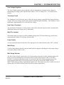
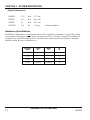
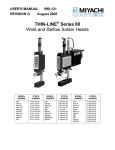
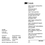
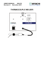
USER'S MANUAL
990-070
Revision C December 2011
THERMOCOUPLE WELDER
Copyright © 1990, 2002, 2007 Miyachi Unitek Corporation
The engineering designs, drawings and data contained herein are the proprietary work of
MIYACHI UNITEK CORPORATION and may not be reproduced, copied, exhibited or
otherwise used without the written authorization of MIYACHI UNITEK CORPORATION.
Printed in the United States of America.
Revision Record
Revision
EO
Date
Basis of Revision
5/90
Original Manual
A
19161
2/02
1. Add Unitek Peco™ name
2. Update manual
B
21443
6/07
Correct error in Table of Contents and update to Miyachi
Unitek corporate logo.
C
41646
12/11
Updated to Miyachi Unitek labeling
THERMOCOUPLE WELDER
ii
990-070
FOREWORD
Thank you for purchasing a Miyachi Unitek Thermocouple Welder.
Upon receipt of your equipment, please thoroughly inspect it for shipping damage prior to its
installation. Should there be any damage, please immediately contact the shipping company to file a
claim, and notify Miyachi Unitek Corporation at:
1820 South Myrtle Avenue
P.O. Box 5033
Monrovia, CA 91017-7133
Telephone: (626) 303-5676
FAX:
(626) 358-8048
e-mail:
[email protected]
The purpose of this manual is to supply operating and maintenance personnel with the information
needed to properly and safely operate and maintain the Thermocouple Welder.
We have made every effort to ensure that the information in this manual is accurate and adequate.
Should questions arise, or if you have suggestions for improvement of this manual, please contact us at
the above location/numbers.
Miyachi Unitek Corporation is not responsible for any loss due to improper use of this product.
THERMOCOUPLE WELDER
990-070
iii
SAFETY NOTES
This instruction manual describes how to operate, maintain and service the Thermocouple Welder, and
provides instructions relating to its SAFE use. Procedures described in this manual MUST be
performed, as detailed, by QUALIFIED and TRAINED personnel.
For SAFETY, and to effectively take advantage of the full capabilities of the tester, please read these
instruction manuals before attempting to use the workstation.
Procedures other than those described in this manual or not performed as prescribed in it, may expose
personnel to electrical hazards.
After reading this manual, retain it for future reference when any questions arise regarding the proper
and SAFE operation of the tester.
Please note the following conventions used in this manual:
WARNING: Comments marked this way warn the reader of actions which, if not followed, might
result in immediate death or serious injury.
CAUTION: Comments marked this way warn the reader of actions which, if not followed, might result
in either damage to the equipment, or injury to the individual if subject to long-term exposure to the
indicated hazard.
THERMOCOUPLE WELDER
iv
990-070
CONTENTS
Page
Revision Record ......................................................................................................................................... ii
Foreword ................................................................................................................................................... iii
Safety Notes .............................................................................................................................................. iv
CHAPTER 1: SYSTEM DESCRIPTION .......................................................................................... 1-1
Introduction .............................................................................................................................. 1-1
Power Supply ............................................................................................................................ 1-1
Description ........................................................................................................................ 1-1
Line Voltage ...................................................................................................................... 1-1
Line Current Ratings ......................................................................................................... 1-1
60/50 Hz Operation ........................................................................................................... 1-2
Standby Power ................................................................................................................... 1-2
Stored Energy Rating ........................................................................................................ 1-2
Welding Speed .................................................................................................................. 1-2
Capacitor Bank .................................................................................................................. 1-2
Line Voltage Regulator ..................................................................................................... 1-3
Turndown Circuit .............................................................................................................. 1-3
Line Failure Turndown ...................................................................................................... 1-3
Weld Fire Lockout ............................................................................................................ 1-3
Power Switch ..................................................................................................................... 1-3
Weld Ready ....................................................................................................................... 1-3
Wire Gauge Selector ......................................................................................................... 1-4
Physical Dimensions ......................................................................................................... 1-4
Handpiece Specifications ......................................................................................................... 1-4
Wire Gauge Diameter Specifications ................................................................................ 1-5
Initiation ............................................................................................................................ 1-5
Safety Features .................................................................................................................. 1-5
Physical Dimensions ......................................................................................................... 1-6
Argon Purge Gas ............................................................................................................... 1-6
Gas Flow ........................................................................................................................... 1-6
Argon Purge Gas Shutoff .................................................................................................. 1-7
THERMOCOUPLE WELDER
990-070
v
CONTENTS (Continued)
Page
CHAPTER 2: INSTALLATION ......................................................................................................... 2-1
Section I. Power Supply Installation .............................................................................................. 2-1
Power Supply ............................................................................................................................ 2-1
Section II. Thermocouple Wire Preparation ................................................................................... 2-3
Insulation Stripping .................................................................................................................. 2-3
Handpiece Wire Clamping Jaws Installation ........................................................................... 2-4
Wire Clamp Jaw Removal and Insertion ........................................................................... 2-4
CHAPTER 3: OPERATING INSTRUCTIONS ................................................................................ 3-1
Section I. Operation ........................................................................................................................ 3-1
CHAPTER 4: USER MAINTENANCE ............................................................................................. 4-1
Section I. Handpiece Maintenance ................................................................................................. 4-1
Wire Clamp Jaws ...................................................................................................................... 4-1
Handpiece Cable Replacement ................................................................................................. 4-1
Section II. Weld Chamber Maintenance ......................................................................................... 4-4
CHAPTER 5: SERVICE ...................................................................................................................... 5-1
Section I. Calibration ...................................................................................................................... 5-1
Section II. Troubleshooting ............................................................................................................ 5-1
Thermocouple Weld is Dirty or Inconsistent ........................................................................... 5-1
Poor Welds or Failure to Weld ................................................................................................. 5-1
No Output ................................................................................................................................. 5-1
Thermocouple Stuck in Wire Clamp Tube ............................................................................... 5-1
Section III. Repair Service .............................................................................................................. 5-2
Technical Assistance ................................................................................................................ 5-2
Telephone Service ............................................................................................................. 5-2
Factory Service Repair ...................................................................................................... 5-2
ILLUSTRATIONS
Figure
Title
Page
1-1
2-1
2-2
3-1
Front and Back Picture of TCW ........................................................................................ 1-2
TCW Schematic, Sheet 2, Power Connections ................................................................. 2-2
Wire Clamp Jaw Assembly ............................................................................................... 2-4
Thermocouple Wire Insertion Procedure .......................................................................... 3-1
THERMOCOUPLE WELDER
vi
990-070
CHAPTER 1
SYSTEM DESCRIPTION
Introduction
The Miyachi Unitek™ Model TCW Thermocouple Welder, Stock Number 01-196-02, is a manual feed
thermocouple welder designed to weld thermocouple wires together to form a thermocouple junction,
uniform in size, and without detrimental oxide layers when used with argon cover gas. Four different size
Wire Clamp Jaws, which are inserted into the TCW Handpiece, permit joining of most thermocouple wire
materials that ranges in diameter from 38 AWG (.0040 inch) to 20 AWG (.0320 inch). The circuitry is solid
state, with components conservatively rated when used within the maximum specified repetition rates. The
unique charging circuit uses thyristors to provide high reliability and precise charging intervals. Operator
safety is ensured through the use of multiple earth ground connections.
Power Supply
Description
The Model TCW combines capacitor discharge power supply and Tungsten Inert Gas (TIG) welding
technology to make a thermocouple junction.
Line Voltage
Line voltage is 115, 208, or 230 Volts, 60/50 Hz. The Thermocouple Welder (TCW) is a multi-voltage
unit is normally connected for 115V, 60/50 Hz operation unless otherwise specified on the nameplate
and the label attached to the line cord. The actual line voltage should be within ±13% of the nominal
voltage for which the TCW is connected.
Line Current Ratings
Nominal Line
Voltage
(VRMS)
115
Line Voltage
Range
(VRMS)
100 – 130
Line Frequency
Hz
Circuit Breaker
Size – Amps
No. of Breakers
Required
50/60
.5
1
208
230
180 – 235
200 – 260
50/60
50/60
.3
.3
2
2
THERMOCOUPLE WELDER
990-070
1-1
CHAPTER 1: SYSTEM DESCRIPTION
60/50 Hz Operation
The TCW is a dual-frequency machine that does not require calibration for operation at 50 or 60 Hz.
Standby Power
Standby power is approximately 15 watts.
Stored Energy Rating
1.5 to 190 watt-seconds (joules).
Welding Speed
The actual weld time is less than 0.1 seconds and the time for the circuitry to recharge is a maximum of
3 seconds. The maximum number of welds per minute is limited to how fast the Handpiece can be
loaded and inserted into the Weld Chamber.
Capacitor Bank
The Capacitor Bank is 18,300 µ ± 5% at 20 degrees Celsius. At full rating, the Capacitor Bank is
operated at 144 volts.
Figure 1-1. Front and Back Views of Thermocouple Welder.
THERMOCOUPLE WELDER
1-2
990-070
CHAPTER 1: SYSTEM DESCRIPTION
Line Voltage Regulator
The Line Voltage regulator ensures that the welds are independent of changes in line voltage by
maintaining the voltage on the capacitor bank within ± 0.25% of setting for a ± 13% change in line
voltage.
Turndown Circuit
The Turndown Circuit allows the user to reduce the energy setting by using the Wire Gauge Selection
Control. The excess energy stored in the capacitor bank is dissipated internally. The Turndown Circuit
dead-band is approximately 0.6% of the full scale voltage.
Line Failure Turndown
The Line Failure Turndown is a safety feature which ensures that the capacitor bank is automatically
discharged whenever the input power is interrupted.
Weld Fire Lockout
This feature helps prevent poor welds by inhibiting firing of the TCW until the energy stored in the
capacitor bank is within 1% of the pre-selected value.
Power Switch
A rocker switch disconnects both sides of the input power line when switched to the “OFF” position.
Weld Ready
A yellow lamp indicates that the capacitor bank has been charged or discharged to the proper voltage
level and is ready to make a weld.
Wire Gauge Selector
The Wire Gauge Selector controls the level of stored energy necessary to make a thermocouple weld.
Energy levels are indicated for each American Wire Gauge (AWG) from 38 AWG to 20 AWG.
Because of variations in the thermocouple wire diameters and in the melting characteristics of the
various thermocouple alloys, it may be necessary to increase or decrease the WIRE GAUGE
SELECTOR setting to produce a good thermocouple weld. This control may also be used to increase or
decrease the size of the weld bead to meet specific customer requirements.
THERMOCOUPLE WELDER
990-070
1-3
CHAPTER 1: SYSTEM DESCRIPTION
Physical Dimensions
HEIGHT
6 7/8
inch
(17.5 cm)
WIDTH
10 ¼
inch
(26.0 cm)
DEPTH
10
inch
(25.4 cm)
WEIGHT
16.2
lbs
( 7.4 kg)
Includes Handpiece
Handpiece Specifications
The Model TCW Handpiece is not supplied with any Wire Clamp Jaw Assemblies. A single Wire Clamp
Jaw Assembly of the proper gauge is required to operate the TCW. Four Wire Clamp Jaw Assemblies are
available for use with different gauge wires. The table below defines which Wire Clamp Jaw Assembly
should be used with each wire diameter size.
Wire Size
AWG
Stock
No.
Model
No.
ID
No.
38-32
10-293-01
TCWCS38
1
31-27
10-294-01
TCWCS31
2
26-23
10-295-01
TCWCS26
3
22-20
10-296-01
TCWCS22
4
THERMOCOUPLE WELDER
1-4
990-070
CHAPTER 1: SYSTEM DESCRIPTION
Wire Gauge Diameter Specifications
The table below defines the maximum outer jacket insulation size for each wire gauge. It does not refer
to the insulation covering each wire.
Nominal
AWG
Wire Size
Diameter
Max Insulation
Diameter
inch
mm
inch
mm
38
.0040
.1016
.038
0.97
37
.0045
.1143
.038
36
.0050
.1270
35
.0056
34
Nominal
AWG
Wire Size
Diameter
Max Insulation
Diameter
inch
mm
inch
mm
28
.0126
.3200
.055
1.40
0.97
27
.0142
.3607
.055
1.40
.038
0.97
26
.0159
.4039
.124
3.15
.1422
.038
0.97
25
.0179
.4547
.124
3.15
.0063
.1600
.038
0.97
24
.0201
.5105
.124
3.15
33
.0071
.1803
.038
0.97
23
.0226
.5740
.124
3.15
32
.0080
.2032
.038
0.97
22
.0253
.6426
.159
4.04
31
.0089
.2261
.055
1.40
21
.0285
.7239
.159
4.04
30
.0100
.2540
.055
1.40
20
.0320
.8128
.159
4.04
29
.0113
.2870
.055
1.40
Initiation
The Handpiece must be correctly inserted into the Weld Chamber to initiate firing. The two
thermocouple wires loaded in the Handpiece must touch the Arc Button located inside the Weld
Chamber in order to initiate a weld. The firing sequence ensures that the Handpiece is double earth
grounded for maximum operator safety. Internal power supply filtering prevents premature firing due to
radio frequency interference.
Safety Features
Double earth grounded techniques eliminate the possibility of electrical shock to the operator. The
Handpiece used to hold the thermocouple wires is earth grounded to the TCW chassis using a nonremovable cable. The length of the cable prevents injury to the Handpiece should it fall off a table or
bench that is a minimum of 30 inches high. When the Handpiece is placed in the Weld Chamber, a
solenoid mechanically clamps the Handpiece, creating a second earth ground path.
THERMOCOUPLE WELDER
990-070
1-5
CHAPTER 1: SYSTEM DESCRIPTION
Physical Dimensions
BODY LENGTH
4
inch
(10.16 cm)
BODY DIAMETER
¾
inch
( 1.91 cm)
WIRE CLAMP LENGTH
¾
inch
( 1.91 cm)
WIRE CLAMP DIAMETER
¼
inch
( 0.64 cm)
WEIGHT
.2
lbs
(91
gm)
Argon Purge Gas
Thermocouple welding is performed in an argon filled Weld Chamber which is located on the center,
upper face of the TCW. Argon purge gas is necessary to prevent thermocouple joint oxidation during
the welding process.
NOTE: Nitrogen is not effective as a purge gas.
Gas Flow
3 cubic feet per hour, nominal.
Argon Purge Gas Shutoff
An internal solenoid valve blocks the flow of argon purge gas to the Weld chamber when input power to
the TCW is turned off.
NOTE: For this system to be economical, the user must eliminate all leaks in the gas system feeding
the Model TCW. When the input power is on, gas flow is continuous. An internal gas reservoir, located
between the purge gas input connector and the shutoff solenoid, stores a sufficient amount of argon
purge gas to immediately clear out the Weld Chamber when the TCW is turned back on.
THERMOCOUPLE WELDER
1-6
990-070
CHAPTER 2
INSTALLATION
Section I. Power Supply Installation
Power Supply
CAUTION: Do not connect the Thermocouple Welder to the power line at this time. Check the voltage
label on the line cord. At the time of shipment, the voltage for which the Thermocouple Welder was
connected was marked on the line cord. Do not connect the Thermocouple Welder to any voltage without
properly changing the internal connections.
The TCW was assembled at the factory for operation at a specific line voltage. If the TCW is used on a line
voltage other than the one for which it is connected, serious damage can result. Most Thermocouple
Welders are shipped from the factory wired for 115 volt, 50/60 Hz operation.
To check whether the TCW is connected for 115 or 230 volts, follow steps below:
•
Turn the WIRE GAUGE SELECTOR fully counter-clockwise to 40. Verify that the POWER switch
is in the “OFF” position and that the line cord is disconnected.
•
If power was previously applied, wait one minute to ensure that the Capacitor bank is fully
discharged.
•
Loosen the four screws which secure the cover and lift the cover straight up to remove it. The
different transformer connections and circuit breakers for each specific line voltage are illustrated in
figure 2-1.
•
Replace the cover and tighten the screws. Change the line cord plug, if necessary. If necessary,
change or replace the voltage label on the line cord to show the correct operating voltage.
Miyachi Unitek recommends that the Thermocouple Welder (TCW) be installed in a well ventilated area,
free of dirt and moisture. The Thermocouple Welder is a self contained unit designed to minimize
installation and setup time.
Connect the Purge Gas Inlet Port, located on the rear panel of the TCW, to a PROPERLY FILTERED
ARGON GAS SUPPLY using 0.25” O.D. x 0.17” I.D., 120 PSI, plastic tubing. Turn ON the purge gas
supply. Set the Pressure Regulator to 50 PSIG. Set the Flow Regulator for 3 cubic feet per hour. Repair
leaks, if necessary.
THERMOCOUPLE WELDER
990-070
2-1
CHAPTER 2: INSTALLATION
(L2) TO 115VAC
SOLENOID VALVE
Primary Wiring for 115VAC Models
CB1
0.05A
C2
0.005
S1A
1
T1
6
C1
0.01
2
P1
S1B
7
8
3
4
9
10
5
J14
(L2) TO 115VAC
SOLENOID VALVE
Primary Wiring for 208VAC Models
CB1
0.03A
C2
0.005
1
T1
6
C1
0.01
CB2
0.03A
P1
S1A
2
S1B
7
8
3
4
9
10
5
J14
(L2) TO 115VAC
SOLENOID VALVE
Primary Wiring for 230VAC Models
CB1
0.03A
C2
0.005
P1
S1A
1
T1
6
C1
0.01
CB2
0.03A
2
S1B
3
4
7
8
9
5
10
J14
Figure 2-1. Power Supply Connections
THERMOCOUPLE WELDER
2-2
990-070
CHAPTER 2: INSTALLATION
Section II. Thermocouple Wire Preparation
Insulation Stripping
The jacket insulation and the insulation covering both thermocouple wires must be stripped back a
MINIMUM distance from the end of the wire where the weld is to take place. Proper removal of the
insulation allows the bare thermocouple wires to protrude a minimum distance from the end of the
Handpiece Wire Clamping Jaws. Mechanical strippers with oval shaped cutters work best. Do not use
Thermal Strippers with Teflon Coated Wires. Thermal stripping Teflon leaves a thin Teflon coating on the
wires, preventing weld current from flowing. When properly stripped, the bare thermocouple wires will be
of equal length, parallel, and free of insulation residue. The table below gives the minimum wire stripping
length for each wire size.
Wire Size
AWG
Stock No.
Model No.
ID No.
Strip Length
Inches
Strip Length
MM
38 – 32
31 – 27
26 – 23
22 – 20
10-293-01
10-294-01
10-295-01
10-296-01
TCWCS38
TCWCS31
TCWCS26
TCWCS22
1
2
3
4
.200
.200
.200 - .220
.200 - .220
5.08
5.08
5.08 – 5.59
5.08 – 5.59
The recommended tolerance on Strip Length is –0, +.010 inches (-0, +0.25 mm). Any strip length greater
than those shown above is acceptable.
The TCW Handpiece can be used with non-insulated thermocouple wire. Non-insulated wire must protrude
a MINIMUM of .135 inches (3.43 mm) from the closed Wire Clamp Jaws.
THERMOCOUPLE WELDER
990-070
2-3
CHAPTER 2: INSTALLATION
Handpiece – Wire Clamping Jaws Installation
Wire Clamp Jaw Removal and Insertion
Loosen the set screws that hold each Wire Clamp Jaw in place. Pull each jaw straight out of the
Handpiece. See figure 2-2.
Upper Setscrew
Handpiece
Body
Lower Setscrew
Align Here
Upper Wire
Clamp Jaw
Align Here
Lower Wire
Clamp Jaw
Figure 2-2. Wire Clamp Jaw Assembly
To replace the Upper Wire Clamp Assembly, open the Handpiece by sliding the black Loading Button
back toward the square part of the Handpiece. Insert the Wire Clamp Jaw, CONTAINING THE GUIDE
TUBE, into the upper half of the Handpiece. Line up the flat wedge shaped face on the Wire Clamp Jaw
with the flat surface on the upper Handpiece face. Tighten the set screw.
To replace the Lower Wire Clamp Assembly, insert the remaining Wire Clamp Jaw into the lower half
of the Handpiece. Line up the flat wedge shaped face on the Wire Clamp Jaw with the flat surface on
the upper Handpiece face. Tighten the set screw. Close the Handpiece by sliding the black Loading
Button forward. Both halves should be flush at the tip when the tip is closed.
Do not mix Wire Clamp sets. The identification code on the upper Wire Clamp Jaw must match the
identification code on the lower Wire Clamp Jaw.
THERMOCOUPLE WELDER
2-4
990-070
CHAPTER 3
OPERATING INSTRUCTIONS
Section I. Operation
•
Turn ON the purge gas supply. Set the Pressure Regulator to 50 PSIG. Set the Flow Regulator for 3
cubic feet per hour.
•
Switch the POWER SWITCH to “ON”. Purge gas from the reservoir will immediately fill the Weld
Chamber, making the TCW ready to use. When replacing the purge gas tank or if the purge gas line has
been opened, wait 5 minutes for the purge gas to replace the air in the purge gas line, reservoir, and
Weld Chamber. See Chapter 2.
•
Set the WIRE GAUGE SELECTOR to the desired wire gauge size. The WELD READY lamp may
flicker and go OFF instead of staying ON when the WIRE GAUGE SELECTOR is turned
COUNTERCLOCKWISE. The first weld may be safely made and the READY LAMP will turn ON for
subsequent welds.
•
Grasp the Handpiece in either hand. Slide the black Loading Button back toward the square part of the
Handpiece. Using the opposite hand, insert the stripped end of the thermocouple wire into the large
open end on the back of the Upper Wire Clamp Jaw. Feed the wire into the large open end on the back
of the Upper Wire Clamp Jaw. Feed the wire into the tube until it stops. If the insulated wire slides
through the tube without stopping, clamp the BARE wire so that it protrudes a minimum of .135 inches
(3.43 mm) from the end of the Wire Clamp Jaw. See figure 3-1.
Clamp the thermocouple wires together by closing the Handpiece.
Wire Clamp Tube
Thermocouple
A. Wire Clamp Tube, Overview
Wires Must
Touch When
Clamped
Wire Clamp Tube
Thermocouple
B. Wire Clamp Tube, Close-up
Figure 3-1. Thermocouple wire insertion procedure.
NOTE: It may be more comfortable to feed the thermocouple wire into the Handpiece with your
dominant hand, while using the other hand to hold and operate the Handpiece. The black Loading
THERMOCOUPLE WELDER
990-070
3-1
CHAPTER 3: OPERATING INSTRUCTIONS
Button can be placed on either side of the Handpiece to accommodate left or right hand operation. See
Chapter 4.
•
Verify that the WELD READY lamp is on and then gently slide the closed Wire Clamp Jaws into the
Weld Chamber. When the ends of the thermocouple wires touch the Arc Button, located inside the
Weld Chamber, a solenoid lightly clamps the Wire Clamp Jaws and then automatically fires the power
supply. Remove the Handpiece after the “thump” sound has occurred, which indicates that the TCW has
fired.
•
Open the Wire Clamp Jaws and remove the welded thermocouple wire. The weld bead should appear
round and without oxidation. It should not be necessary to change the wire gauge setting more than 2 or
3 wire sizes. Adjust the WIRE GAUGE SELECTOR to produce the desired weld bead. Turning the
Control CLOCKWISE will INCREASE the size of the weld bead.
NOTE: If the weld bead is too large, it cannot be pulled back through the Wire Clamp guide tube. See
Chapter 5, Section II, Troubleshooting.
THERMOCOUPLE WELDER
3-2
990-070
CHAPTER 4
USER MAINTENANCE
Section I. Handpiece Maintenance
Wire Clamp Jaws
With use, the Upper Wire Clamp Jaw will accumulate wire insulation and metal particles inside the Guide
Tube. The buildup rate depends on the number of thermocouple welds made, the thermocouple insulation
material, and the thermocouple wire material. The larger size wires will accumulate particles at a faster rate.
To clean both Wire Clamps, remove them from the Handpiece and place them in an ultrasonic cleaner. Add
cleaning solvent such as Micro Model 8790-00 Liquid Lab Cleaner, distributed by Cole-Parmer.
WARNING: Do not use a wire to clean the upper Wire Clamp guide tube. Doing so may cause internal
damage to the guide tube.
Handpiece Cable Replacement
The Handpiece Cable is very flexible and should last many years with careful use. Should the insulation
become cracked at either the Handpiece or Power Supply front attachments, return the unit to Unitek
Miyachi. See Chapter 5, Section III, Repair Service.
Section II. Weld Chamber Maintenance
Over time, the thermocouple weld bead will become dirty in appearance, signaling an undesirable buildup
of thermocouple weld material on the Arc Button located inside of the Weld Chamber. If the Arc Button is
not periodically resurfaced, the weld quality will deteriorate to where a weld cannot be made.
The buildup rate depends on the number of thermocouple welds made, the thermocouple wire material, and
the thermocouple wire diameter. Buildup occurs faster with large gauge wires such as 20-22 AWG and
usually appears as a bright metallic deposit on the face of the Arc Button.
Should this occur, return the unit to Unitek Miyachi. See Chapter 5, Section III, Repair Service.
THERMOCOUPLE WELDER
990-070
4-1
CHAPTER 5
SERVICE
Section I: Calibration
The Model TCW does not require calibration. Component tolerances and stability are such that the
Capacitor Bank Voltage will not vary from Power Supply to Power Supply by more than 4% for the same
WIRE GAUGE SELECTOR setting.
Section II. Troubleshooting
Thermocouple Weld is Dirty or Inconsistent
Return the unit to Unitek Miyachi. See Section III, Repair Service.
Poor Welds or Failure to Weld
a
b
c
d
Improper wire gauge selection.
Wrong Wire Clamp Jaws for the thermocouple wire size.
Poor electrical contact to thermocouple wires.
Heavy oxide or corrosion on the thermocouple wires. Check gas flow. Keep thermocouple in Weld
Chamber for one second before removing.
NOTE: A dark residue is normal with type J thermocouples.
e
f
g
Thermocouple wires are different lengths.
Thermocouple wires are not touching each other at the tip.
Handpiece is forced past the clamping position during welding.
No Output
Bad Control Board Assembly, Weld Capacitor, or Arc Button or Wire Clamp Solenoid malfunction. Unitek
Miyachi strongly recommends that the Power Supply be returned to the factory for service. See Section III,
Repair Service.
Thermocouple Stuck in Wire Clamp Tube
If the weld bead is larger than the inside of the Wire Clamp Tube, the thermocouple wire cannot be removed
without first cutting off the weld bead using a flush cutting wire cutter or a sharp knife. Avoid cutting or
nicking the Wire Clamp Tube.
THERMOCOUPLE WELDER
990-070
5-1
CHAPTER 5: SERVICE
Section III. Repair Service
Technical Assistance
If you need further technical assistance, please contact either your authorized service agent or Unitek
Miyachi at the postal or e-mail address or telephone or FAX number shown in the Foreword of this manual.
Before calling please obtain the model number, stock number, and the serial number from the name plate on
the product.
Telephone Service
Call the our Repair Department at the telephone number shown in the Foreword of this manual. Before
calling, please obtain the model number and serial number from the identification plate on the rear
panel.
Factory Service Repair
We provide a repair service for both warranty and non-warranty repairs. Call our Customer Service
Department at the telephone number shown in the Foreword of this manual for a Return Material
Authorization number. All equipment to be returned to us for repair must be shipped prepaid.
Please include information concerning the type of problem you are experiencing. Include with the
shipping information the name and telephone number of the person whom we should call with the
estimated cost of repairs.
5-2
THERMOCOUPLE WELDER
990-070