1
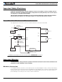
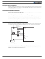
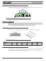
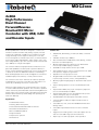
MDC2xxx
2x60A
High Performance
Dual Channel
Forward/Reverse
Brushed DC Motor
Controller with USB, CAN
and Encoder Inputs
Roboteq’s MDC2xxx controller is designed to convert commands received from an RC radio, Analog Joystick, wireless
modem, PC (via RS232 or USB) or microcomputer into high
voltage and high current output for driving one or two DC
motors. Designed for maximal ease-of-use, it is delivered with
all necessary cables and hardware, and is ready to use in minutes. Using CAN bus, up to 127 controllers can be networked at
up to 1Mbit/s on a single twisted pair.
Features List
•
The controller features a high-performance 32-bit microcomputer and quadrature encoder inputs to perform advanced
motion control algorithms in Open Loop or Close Loop (Speed
or Position) modes. The MDC2xxx features several Analog,
Pulse and Digital I/Os which can be remapped as command or
feedback inputs, limit switches, or many other functions.
Built-in high-power power drivers for two brushed DC
motors at up to 60A output per channel
•
•
Orderable as single channel version up to 120A
The controller’s two motor channels can either be operated
independently or mixed to set the direction and rotation of a
vehicle by coordinating the motion of each motor.
Numerous safety features are incorporated into the controller
to ensure reliable and safe operation. The controller's operation
can be extensively automated and customized using Basic Language scripts. The controller can be reprogrammed in the field
with the latest features by downloading new operating software from Roboteq.
Applications
•
•
•
•
•
•
•
•
•
USB, RS232, 0-5V Analog, or Pulse (RC radio) command
modes
•
•
CAN bus interface up to 1Mbit/s
•
•
Terrestrial and Underwater Robotic Vehicles
Automatic Guided Vehicles
Police and Military Robots
Operates from a single power source
Programmable current limit for each channel up to 2x60A
for protecting controller, motors, wiring and battery
Built-in programming language for automation and customization
•
Up to 4 Analog Inputs for use as command and/or feedback
•
Up to 5 Pulse Width, Duty Cycle or Frequency Inputs for
use as command and/or feedback
•
Up to 6 Digital Inputs for use as Deadman Switch, Limit
Switch, Emergency stop or user inputs
•
•
Dual Quadrature Encoder inputs with 32-bit counters
2 general purpose 40V, 1A output for brake release or
accessories
•
Selectable min, max, center and deadband in Pulse and
Analog modes
•
Selectable exponentiation factors for each command
inputs
•
Trigger action if Analog, Pulse or Encoder capture are outside user selectable range (soft limit switches)
•
Open loop or closed loop speed control operation
Flight simulators
Telepresence Systems
Full forward & reverse control on each channel. Four quadrant operation. Supports regeneration
•
Industrial Automation
Tracking, Pan & Tilt systems
Auto switch between USB, RS232, CAN, Analog, or Pulse
based on user-defined priority
Animatronics
MDC2xxx Motor Controller Datasheet
1
•
Closed loop position control with analog or pulse/frequency feedback
•
Stall detection and selectable triggered action if Amps is
outside user-selected range
•
Precise speed and position control when Encoder feedback is used
Short circuit protection with selectable sensitivity levels
•
•
PID control loop with separate gains for each channel
•
•
•
Optional Mixed control (sum and difference) for tank-like
steering
•
Configurable Data Logging of operating parameters on
RS232 Output for telemetry or analysis
•
•
Built-in Battery Voltage and Temperature sensors
•
•
•
Overvoltage and Undervoltage protection
Programmable Watchdog for automatic motor shutdown
in case of command loss
Overtemperature protection
Diagnostic LED
Open frame or enclosed design with heat conducting
bottom plate
Optional 12V backup power input for powering safely the
controller if the main motor batteries are discharged
•
•
Efficient heat sinking. Operates without a fan in most
applications
Power Control wire for turning On or Off the controller
from external microcomputer or switch
Power wiring 0.25" Faston tabs
•
•
No consumption by output stage when motors stopped
•
•
•
•
•
Regulated 5V output for powering Encoders, RC radio,
RF Modem or microcomputer
•
Separate Programmable acceleration and deceleration
for each motor
•
Separate Programmable maximum forward and reverse
power
•
•
Support for CANopen and two simplified CAN protocols
•
5.5” (139.7mm) L, 5.5” W (139.7mm), 1.0” (25mm) H
-40o to +85o C operating environment
0.5 lbs (250g)
Easy configuration, tuning and monitory using provided
PC utility
Field upgradeable software for installing latest features
via the internet
Ultra-efficient 3 mOhm High-Efficiency version ON resistance MOSFETs
Orderable Product References
TABLE 1.
2
Reference
Number of Channels
Amps/Channel
Volts
Cooling
MDC2230
2
60
30
Conduction Plate
MDC2230S
1
120
30
Conduction Plate
MDC2250
2
60
50
Conduction Plate
MDC2250S
1
120
50
Conduction Plate
MDC2460
2
60
60
Conduction Plate
MDC2460S
1
120
60
Conduction Plate
MDC2xxx Motor Controller Datasheet
Version 1.3. April 05, 2014
Power Wires Identifications and Connection
Important Safety Disclaimer
Dangerous uncontrolled motor runaway condition can occur for a number of reasons, including, but not
limited to: command or feedback wiring failure, configuration error, faulty firmware, errors in user script or
user program, or controller hardware failure.
The user must assume that such failures can occur and must make his/her system safe in all conditions.
Roboteq will not be liable in case of damage or injury as a result of product misuse or failure.
Power Wires Identifications and Connection
The diagram below shows how to wire the controller and how to turn power On and Off.
F2
1A
SW1 Main
On/Off Switch 1A
PwrCtrl
Note 1
M1+
Ground
Motor 1
Backup
Battery
M1Diode
>20A
Resistor
1K, 0.5W
Note 3
VMot
VMot
F1
Note 4
+
M2+
Note 2
Motor 2
SW2
Emergency
Contactor or
Cut-off Switch
-
M2-
Ground
Ground
I/O Connector
Main
Battery
Note 5
Do not Connect!
FIGURE 8. Powering the controller. Thick lines identify MANDATORY connections
Important Warning
Carefully follow the wiring instructions provided in the Power Connection section of the User Manual. The
information on this datasheet is only a summary.
Mandatory Connections
It is imperative that the controller is connected as shown in the above diagram in order to ensure a safe and trouble-free operation. All connections shown as thick black lines are mandatory. The controller must be powered On/
Off using switch SW1on the Power Control Header. Use a suitable high-current fuse F1 as a safety measure to
prevent damage to the wiring in case of major controller malfunction.
MDC2xxx Motor Controller Datasheet
3
Emergency Switch or Contactor
The battery must be connected in permanence to the controller’s VMot power via an input emergency switch or
contactor SW2 as additional safety measure. The user must be able to deactivate the switch or contactor at any
time, independently of the controller state.
Precautions and Optional Connections
Note 1: Backup battery to ensure motor operation with weak or discharged batteries, connect a second battery to
the Power Control wire/terminal via the SW1 switch.
Note 2: Use precharge 1K, 0.5W Resistor to prevent switch arcing.
Note 3: Insert a high-current diode to ensure a return path to the battery during regeneration in case the fuse is
blown.
Note 4: Optionally ground the VMot tabs when the controller is Off if there is any concern that the motors could
be made to spin and generate voltage in excess of 30V (MDC2230), 50V (MDC2250) or 60V (MDC2460).
Note 5: Beware not to create a path from the ground pins on the I/O connector and the battery minus terminal.
Use of Safety Contactor for Critical Applications
An external safety contactor must be used in any application where damage to property or injury to person can
occur because of uncontrolled motor operation resulting from failure in the controller’s power output stage.
F2
1A
SW1 Main
On/Off Switch 1A
PwrCtrl
Ground
Resistor
1K, 0.5W
Diode
>20A
F1
VMot
Digital Out
to +40V Max
I/O Connector
+
Ground
Main
Battery
FIGURE 9. Contactor wiring diagram
The contactor coil must be connected to a digital output configured to activate when “No MOSFET Failure”. The
controller will automatically deactivate the coil if the output is expected to be off and battery current of 1A or
more is measured for more than 0.5s. This circuit will not protect against other sources of failure such as those
described in the “Important Safety Disclaimer” on page 3.
4
MDC2xxx Motor Controller Datasheet
Version 1.3. April 05, 2014
Single Channel Motor Wiring
Single Channel Motor Wiring
The single channel version of the controller (MDC2230S/MDC2250S/MDC2460S) requires that the output be parallel and that the load be wired as shown in the diagram below.
M
VMOT
M1-
M1+
GND
M2- M2+
VMOT
FIGURE 10. MDC2230S/MDC2250S/MDC2460S wiring diagram
Important Warning
This wiring is only possible on controllers fitted with the Single Channel version of the controller logic.
Dual channel controllers will be damaged if wired as single channel. Verify that the PC utility identifies the
controller as MDC2230S/MDC2250S/MDC2460S before applying power to the load.
Encoder Wiring
The encoder connector is a 6-pin Molex Microfit 3.0, model 43645. Pin assignment is in the table below.
6
1
6
1
FIGURE 11. Encoder connector
TABLE 4.
Pin Number
1
2
3
4
5
6
Signal
5Vout
Enc1A
Enc1B
Enc2A
Enc2B
GND
Controller Mounting
During motor operation, the controller will generate heat that must be evacuated. The published amps rating can
only be fully achieved if adequate cooling is provided. Mount the controller so that the bottom plate makes contact with a metallic surface (chassis, cabinet) to conduct the heat.
MDC2xxx Motor Controller Datasheet
5
Commands and I/O Connections
Connection to RC Radio, Microcomputer, Joystick and other low current sensors and actuators is done via the 15
connector located in front of the board. The functions of many pins vary depending on user configuration. Pin
assignment is found in the table below.
8
1
15
9
FIGURE 12. Connector pin locations
TABLE 5.
Connector Pin
Power
1
Dout
Com
RC
Ana
Dinput
DOUT1
9
Motor Brake
DOUT2
2
Safety Contactor
TxOut
10
RS232Tx
RC5
3
ANA1
DIN5
RxIn
11
ANA4
RC1
12
AnaCmd1 (1)
RS232Rx
RC4
4
5
Default Config
RC3
ANA3
DIN4
AnaCmd2 (1)
DIN1
RCRadio1
DIN3
Unused
GND
13
GND
6
14
CANL
CAN Low
CANH
CAN High
5VOut
7
15
8
RC2
ANA2
DIN6
Unused
DIN2
RCRadio2
Note 1: Analog command is disabled in factory default configuration.
Default I/O Configuration
The controller can be configured so that practically any Digital, Analog and RC pin can be used for any purpose.
The controller’s factory default configuration provides an assignment that is suitable for most applications. The
figure below shows how to wire the controller to two analog potentiometers, an RC radio, and the RS232 port. It
also shows how to connect the two outputs to motor brake solenoids. You may omit any connection that is not
required in your application. The controller automatically arbitrates the command priorities depending on the presence of a valid command signal in the following order: 1-RS232, 2-RC Pulse, 3-None. If needed, use the Roborun+
PC Utility to change the pin assignments and the command priority order.
6
MDC2xxx Motor Controller Datasheet
Version 1.3. April 05, 2014
Enabling Analog Commands
RC Ch2
2
RC Ch1
RS232
Ground
TxOut
RxIn
1
8
1
Motor Brake
Safety Contactor
15
9
Pot 2
Pot 1
FIGURE 13. Factory default pins assignment
Enabling Analog Commands
For safety reasons, the Analog command mode is disabled by default. To enable the Analog mode, use the PC
utility and set Analog in Command Priority 2 or 3 (leave Serial as priority 1). Note that by default the additional
securities are enabled and will prevent the motor from starting unless the potentiometer is centered, or if the
voltage is below 0.25V or above 4.75V. The drawing shows suggested assignment of Pot 1 to ANA1 and Pot 2 to
ANA4. Use the PC utility to enable and assign analog inputs.
CAN Bus Operation
The controller can interface to a standard CAN Bus network, using 3 possible protocols: Standard CANOpen, and
two simplified proprietary schemes (MiniCAN and RawCAN). Please refer to the User Manual for details. USB and
CAN cannot operate at the same time. The controller starts up with CAN available, but CAN will be disabled as
soon as the controller is plugged into USB. To re-enable CAN, disconnect USB and restart the controller.
USB communication
Use USB only for configuration, monitoring and troubleshooting. USB is not a reliable communication method
when used in a electrically noisy environments and communication will not always recover after it is lost without
unplugging and replugging the connector, or restarting the controller. Always prefer RS232 communication when
interfacing to a computer.
MDC2xxx Motor Controller Datasheet
7
Status LED Flashing Patterns
After the controller is powered on, the Power LED will turn on, indicating that the controller is On. The Status LED
will be flashing at a 2 seconds interval. The flashing pattern provides operating or exception status information.
Idle - Waiting for Command
RS232/USB Mode
RC Pulse Mode
Analog Mode
FIGURE 14. Normal Operation Flashing Patterns
Short Detected
Overheat
Under or Over Voltage
Power Stage Off
FIGURE 15. Exception or Fault Flashing Patterns
Additional status information may be obtained by monitoring the controller with the PC utility.
Self-Test and Reset Default Configuration
It is possible to verify that the controller is functioning by activating a self-test that will in turn ramp the motor(s)
up to full forward power and down to full reverse power. Then it toggles each digital output. To activate self-test,
turn off the controller, short RS232 Rx and Tx pins together (Pins 2 and 3 of I/O connector), and turn the controller
on again. The process will repeat until power is turned off and the RS232 is no longer shorted. Activating the selftest also resets the controller settings to factory defaults.
Note: RS232 cannot be connected to PC as this will prevent the controller from entering the self-test mode.
Electrical Specifications
Absolute Maximum Values
The values in the table below should never be exceeded, permanent damage to the controller may result.
TABLE 6.
8
Parameter
Measure point
Battery Leads Voltage
Ground to VMot
Model
Min
Typ
Max
Units
MDC2230
35
Volts
MDC2250
50
Volts
MDC2460
62
Volts
Reverse Voltage on Battery Leads
Ground to VMot
All
Power Control Voltage
Ground to Pwr Control wire
All
MDC2xxx Motor Controller Datasheet
-1
Volts
50
Volts
Version 1.3. April 05, 2014
Electrical Specifications
TABLE 6.
Parameter
Measure point
Model
Motor Leads Voltage
Ground to M1+, M1-, M2+, M2-
Min
Typ
Max
Units
MDC2230
30
Volts
MDC2250
50 (1)
Volts
MDC2460
62 (1)
Volts
Digital Output Voltage
Ground to Output pins
All
30
Volts
Analog and Digital Inputs Voltage
Ground to any signal pin on
15-pin and encoder connectors
All
15
Volts
RS232 I/O pins Voltage
External voltage applied to Rx/
Tx pins
All
15
Volts
Temperature
Board
All
85
oC
Humidity
Board
All
100 (2)
%
-40
Note 1: Maximum regeneration voltage in normal operation. Never inject a DC voltage from a battery or other fixed source
Note 2: Non-condensing
Power Stage Electrical Specifications (at 25oC ambient)
TABLE 7.
Parameter
Measure point
Models
Min
Battery Leads Voltage
Ground to VMot
MDC2230
MDC2250
Motor Leads Voltage
Ground to M1+, M1-,
M2+, M2-
Max
Units
0 (1)
30
Volts
0 (1)
50
Volts
MDC2460
0 (1)
62
Volts
MDC2230
0 (1)
30 (2)
Volts
MDC2250
50 (2)
Volts
MDC2460
62 (2)
Volts
50
Volts
Power Control Voltage
Ground to Power Control wire
All
0 (1)
Minimum Operating Voltage
VMot or Pwr Ctrl
wires
All
9 (3)
Idle Current Consumption
VMot or Pwr Ctrl
wires
All
50
ON Resistance
VMot to M+, plus Mto Ground at 100%
power. Per channel
All
Max Current per channel for
30s
Motor current
Continuous Max Current per
channel
Motor current
Current Limit range
Ch1 or Ch2 Motor
current
MDC2230/50/60
10
MDC2230S/
50S/60S
Ch1 or Ch2 Motor
current
Stall Detection Amps range
MDC2xxx Motor Controller Datasheet
Typ
Volts
100 (4)
150
6
mA
mOhm
MDC2230/50/60
60 (5)
Amps
MDC2230S/
50S/60S
120 (5)(6)
Amps
MDC2230/50/60
100(6)(7)
Amps
MDC2230S/
50S/60S
100 (6)(7)
Amps
50 (8)
60
Amps
10
100 (8)
120 (6)
Amps
MDC2230/50/60
10
60 (8)
60
Amps
MDC2230S/
50S/60S
10
120 (8)
120 (6)
Amps
9
TABLE 7.
Parameter
Measure point
Models
Min
Typ
Max
Units
Stall Detection timeout range
Ch1 or Ch2 Motor
current
All
1
65000 (9)
65000
milliseconds
Short Circuit Detection
threshold (10)
Between Motor wires
or Between Motor
wire and Ground
MDC2230/50/60
140 (11)
400 (11)
Amps
MDC2230S/
50S/60S
280
800
Amps
Short Circuit Detection
threshold
Between Motor wires
and VMot
All
No Protection. Permanent damage will result
Motor Acceleration/Deceleration range
Ch1 or Ch2
All
100
500 (12)
65000
milliseconds
Note 1: Negative voltage will cause a large surge current. Protection fuse needed if battery polarity inversion is possible
Note 2: Maximum regeneration voltage in normal operation. Never inject a DC voltage from a battery or other fixed source
Note 3: Minimum voltage must be present on VMot or Power Control wire
Note 4: Current consumption is lower when higher voltage is applied to the controller’s VMot or PwrCtrl wires
Note 5: Max value is determined by current limit setting. Duration is estimated and is dependent on ambient temperature
cooling condition
Note 6: Current is sum of both synchronized channels. Current must be balanced between channel to obtain max current.
Note 7: Estimate. Limited by case temperature. Current may be higher with better cooling
Note 8: Factory default value. Adjustable in 0.2A increments
Note 9: Factory default value. Time in ms that Stall current must be exceeded for detection
Note 10: Controller will stop until restarted in case of short circuit detection
Note 11: Sensitivity selectable by software
Note 12: Factory default value. Time in ms for power to go from 0 to 100%
Command, I/O and Sensor Signals Specifications
TABLE 8.
10
Parameter
Measure point
Min
Typ
Max
Units
Main 5V Output Voltage
Ground to 5V pins on
4.6
4.75
4.9
Volts
5V Output Current
5V pins on Hall Connector and DSub15
200 (1)
mA
Digital Output Voltage
Ground to Output pins
40
Volts
Digital Output Current
Output pins, sink current
1
Amps
Output On resistance
Output pin to ground
0.75
1.5
Ohm
Output Short circuit threshold
Output pin
1.4
1.75
Input Impedances
AIN/DIN Input to Ground
Digital Input 0 Level
Ground to Input pins
-1
1
Volts
Digital Input 1 Level
Ground to Input pins
3
15
Volts
Analog Input Range
Ground to Input pins
0
Analog Input Precision
Ground to Input pins
0.5
%
Analog Input Resolution
Ground to Input pins
1
mV
Pulse durations
Pulse inputs
20000
Pulse repeat rate
Pulse inputs
50
Pulse Capture Resolution
Pulse inputs
Frequency Capture
Pulse inputs
MDC2xxx Motor Controller Datasheet
1.05
Amps
53
kOhm
5.1
Volts
10
us
250
Hz
1
100
us
10000
Hz
Version 1.3. April 05, 2014
Electrical Specifications
TABLE 8.
Parameter
Measure point
Min
Encoder count
Internal
-2.147
Encoder frequency
Encoder input pins
Typ
Max
Units
2.15
10^9 Counts
250
kHz
Note 1: Sum of all 5VOut outputs
Operating & Timing Specifications
TABLE 9.
Parameter
Measure Point
Command Latency
Command to output change
PWM Frequency
Ch1, Ch2 outputs
Closed Loop update rate
Internal
USB Rate
USB pins
RS232 baud rate
Rx & Tx pins
RS232 Watchdog timeout
Rx pin
Min
10
Typ
Max
Units
0.5
1
ms
18 (1)
20
kHz
1000
Hz
12
115200 (2)
MBits/s
Bits/s
1 (3)
65000
ms
Note 1: May be adjusted with configuration program
Note 2: 115200, 8-bit, no parity, 1 stop bit, no flow control
Note 3: May be disabled with value 0
Scripting
TABLE 10.
Parameter
Measure Point
Scripting Flash Memory
Internal
Max Basic Language programs
Internal
Min
Typ
Max
8192
1000
Units
Bytes
1500
Lines
Integer Variables
Internal
1024
Words (1)
Boolean Variables
Internal
1024
Symbols
Execution Speed
Internal
100 000
Lines/s
50 000
Note 1: 32-bit words
Thermal Specifications
TABLE 11.
Parameter
Measure Point
Model
Min
Max
Units
Board Temperature
Heatsink plate
All
-40
Typ
85 (1)
oC
Thermal Protection range
Heatsink plate
All
80
90 (2)
oC
Power Dissipation
Case
All
30
Watts
Thermal resistance
Power MOSFETs to heatsink
All
2
oC/W
Note 1: Thermal protection will protect the controller power
Note 2: Max allowed power out starts lowering at minimum of range, down to 0 at max of range
MDC2xxx Motor Controller Datasheet
11
Mechanical Specifications
TABLE 12.
Parameter
Measure Point
Min
Typ
Max
Units
Weight
Board
250 (0.5)
g (lbs)
Power Connectors width
Terminal tab
0.25
Inches
0.1" (2.5 mm)
0.25"
0.98"
(25mm)
(6.3 mm)
0.57"
0.7" (17.8mm)
0.3"
(14.5mm)
(7.6 mm)
0.16" (4.0mm)
0.325" (8.3 mm)
FIGURE 16. MDC2xxx side view and dimensions
5.50" (139.7mm)
5.25" (133.4mm)
0.120" (3.0mm)
0.15"
(3.8mm)
0.120" (3.0mm)
0.40" (10.2mm)
0.3" (7.6mm)
2.32" (59.0mm)
2.0" (5.08mm)
4.20" (106.7mm)
0.3" (7.6mm)
0.2" (5.1mm)
0.2" (5.1mm)
0.6" (10.11mm)
1.09"
0.35" (8.9mm)
0.15"
(3.8mm)
5.00" (127.0mm)
5.50" (139 .7mm)
0.35" (8.9mm)
2.75" (69.9mm)
0.24" (6.0mm)
0.65" (16.1mm)
0.40" (10.2mm)
0.15" (3.8mm)
(3.8mm)
0.15" (3.8mm)
0.65" (16.1mm)
3.42" (86.9mm)
1.25" (31.8mm)
3.00" (76.2mm)
FIGURE 17. MDC2xxx top view and dimensions
12
MDC2xxx Motor Controller Datasheet
Version 1.3. April 05, 2014