1
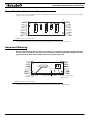
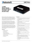
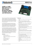
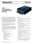
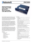
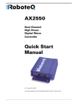
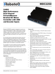
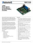
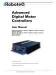
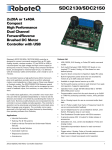
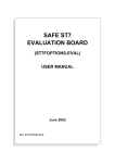
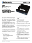
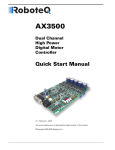
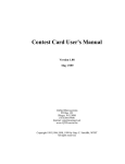
VSX1850
500A
Forward/Reverse
Separate Excitation
DC Motor
Controller
Roboteq’s VSX1850 is a high-current controller for Separate
Excitation DC motors. The controller is composed of a unidirectional half-bridge capable of up to 500A for the motor’s armature, and a 25A bidirectional power bridge for the motor’s
excitation (field).
The controller accepts commands received from a RC radio,
Analog Joystick, wireless modem, or microcomputer to coordinate the armature and field bridge power so that the motor will
move in a precisely controlled manner in the forward or
reversed direction.
The motor may be operated in open or closed loop speed
mode. Using low-cost position sensors, it may also be set to
operate as a heavy-duty position servos. The controller's operation can be extensively automated and customized using Basic
Language scripts.
The controller can be configured, monitored and tuned in realtime using a Roboteq’s free PC utility. The controller can also be
reprogrammed in the field with the latest features by downloading new operating software from Roboteq.
Applications
•
•
•
•
•
•
•
•
•
Electric Vehicles
Key Features
•
•
Built-in high-power driver for Separate Excitation DC
motors at up to 500A
•
•
Secondary 25A full bridge for Excitation power
Telepresence Systems
Animatronics
Industrial Controls
Hydraulic Pumps control
VSX1850 Motor Controller Datasheet
Full forward & reverse motor direction control. Four quadrant operation. Supports regeneration
•
User programmable curve of Excitation power vs. Armature power
•
•
•
Compatible with Serial motors. Unidirectional control only
Operates from a single 10V-50V power source
Programmable current limit up to 500A for protecting controller, motor, wiring and battery.
•
Up to 4 Analog Inputs for use as command and/or feedback
•
Up to 5 Pulse Length, Duty Cycle or Frequency Inputs for
use as command and/or feedback
•
Up to 6 Digital Inputs for use as Deadman Switch, Limit
Switch, Emergency stop or as user inputs
•
Two general purpose 24V, 1.5A output for brake release or
accessories
•
Custom scripting in Basic language. Execution speed
50,000+ lines per second
•
Selectable min, max, center and deadband in Pulse and
Analog modes
•
•
Selectable exponentiation factors on command input
Police and Military Robots
Hazardous Material Handling Robots
Auto switch between RS232, Analog, or Pulse based on
user-defined priority
•
Terrestrial and Underwater Robotic Vehicles
Automatic Guided Vehicles
RS232, 0-5V Analog, or Pulse (RC radio) command modes
•
•
Trigger action at user programmable Analog or Pulse input
levels (soft limit switches)
Open loop or closed loop speed control operation
Closed loop position control with analog or pulse/frequency feedback
1
•
•
•
•
PID control loop
Configurable Data Logging of operating parameters on
RS232 Output for telemetry or analysis
Built-in Battery Voltage and Temperature sensors
Optional 12V backup power input for powering safely the
controller if the main motor batteries are discharged
•
Power Control wire for turning On or Off the controller
from external microcomputer or switch
•
•
No consumption by output stage when motors stopped
•
10 to 32kHz user programmable Pulse Width Modulation
(PWM) output.
•
•
Overvoltage and Undervoltage protection
•
•
•
Watchdog for automatic motor shutdown in case of
command loss
Overtemperature protection
Diagnostic LED
Extruded aluminum, heat sinking enclosure for operation harsh shock and temperature environment
Regulated 5V output for powering RC radio, RF Modem
or microcomputer
•
Efficient heat sinking. Operates without a fan in most
applications.
•
Separate Programmable acceleration and deceleration
rate
Dustproof and weather resistant. IP51 NEMA rating
•
Separate Programmable maximum forward and reverse
power
•
•
Ultra-efficient 0.4 mOhm ON resistance MOSFETs
•
•
•
•
•
•
Orderable as dual channel with one unidirectional 500
output and one bidirectional 25A output
•
Stall detection and selectable triggered action if Amps is
outside user-selected range
•
Short circuit protection with selectable sensitivity levels
•
Power wiring via heavy-duty copper bars
9” (228.5mm) L, 5.5” W (140mm), 1.6” (40mm) H
-40o to +85o C operating environment
3 lbs (1,350g)
Easy configuration, tuning and monitory using provided
PC utility
Field upgradeable software for installing latest features
via the internet
Orderable Product References
2
Reference
Number of Channels
Amps/Channel
Volts
VSX1850
1 Sepex
500A
50V
VSX1850-D
1 Unidirectional. 1 Bidirectional
500A, 25A
50V
VSX1850 Motor Controller Datasheet
Version 1.2. July 20, 2010
Power Wires Identifications and Connection
Power Wires Identifications and Connection
Power connections are made by means of copper bars located at the back of the controller for the high-current
output to the motor armature.
(top)
FIGURE 8. Rear Controller Layout
The connection to motor field is done using Fast-On tabs located on the controller’s front.
Important Warning
Because of the extremely high current on the copper bars, it is imperative that the connection between
the wires and the copper bars be perfect. A poor connection will cause potentially damaging heat to be
generated at the point of contact between the wire lug and the copper bar.
F+
P1
Power
Communication and
I/O Connector
F-
Status
Power and Status LEDs
Power Connectors to
Motor Field
FIGURE 9. Front Controller Layout
The diagram below shows how to wire the controller and how to turn power On and Off.
VSX1850 Motor Controller Datasheet
3
Diode
>20A
Resistor
1K, 0.5W
Note 3
Note 2
PwrCtrl/Yellow
SW1 Main
On/Off Switch 1A
VBat / Mot+
F1
F2
1A
Note 1
F+
Motor
Backup
Battery
F-
Mot-
Earth Tab
Ground
+
Note 4
I/O Connector
Main
Battery
Note 5
Do not Connect!
FIGURE 10. Powering the controller. Thick lines identify MANDATORY connections
Important Warning
Carefully follow the wiring Instructions provided in the Read Me First sheet that comes with the controller, or in the Power Connection section of the User Manual. The information on this datasheet is only a
summary.
Mandatory Connections
It is imperative that the controller is connected as shown in the above diagram in order to ensure a safe and trouble-free operation. All connections shown as thick black lines line are mandatory. The controller must be powered
On/Off using switch SW1on the Power Control tab. Use a suitable high-current fuse F1 as a safety measure to
prevent damage to the wiring in case of major controller malfunction.
The battery must be connected in permanence to the controller’s VBat and Ground copper bars via a high-power
emergency switch SW2 as additional safety measure.
Precautions and Optional Connections
Note1: To ensure motor operation with weak or discharged batteries, connect a second battery to the Power Control tab via the SW1 switch.
Note2: Use precharge 1K, 0.5W Resistor to prevent switch arcing.
Note3: Insert a high-current diode to ensure a return path to the battery during regeneration in case the fuse is
blown.
Note4: Connect the controller’s earth tab to a wire connected to the Earth while the charger is plugged in the AC
main, or if the controller is powered by an AC power supply.
4
VSX1850 Motor Controller Datasheet
Version 1.2. July 20, 2010
Commands and I/O Connection
Note5: Beware not to create a path from the ground pins on the I/O connector and the battery minus terminal.
Commands and I/O Connection
Connection to RC Radio, Microcomputer, Joystick and other low current sensors and actuators is done via the 15pin connector located in front of the controller. The functions of some pins vary depending on controller model
and user configuration. Pin assignment is found in the table below.
8
1
15
9
FIGURE 11. Connector pin locations
TABLE 4.
Connector Pin
Power
1
Dout
Com
RC
Ana
Dinput
DOUT1
9
Brake release
DOUT2
2
Unused
TxOut
10
RS232Tx
RC5
3
ANA1
DIN5
RxIn
11
ANA4
RC1
12
AnaCmd1
RS232Rx
RC4
4
5
Default Config
RC3
ANA3
DIN4
Unused
DIN1
RCRadio1
DIN3
Unused
GND
13
GND
6
14
SCLI
Reserved
SDAI
Reserved
5VOut
7
15
8
RC2
ANA2
DIN6
Unused
DIN2
Unused
Default I/O Configuration
The controller can be configured so that practically any Digital, Analog and Pulse pin can be used for any purpose.
The controller’s factory default configuration provides an assignment that is suitable for most applications. The
figure below shows how to wire the controller to an analog potentiometers, an RC radio, and the RS232 port. It
also shows how to connect the one of the Digital outputs to a motor brake solenoid. You may omit any connection that is not required in your application. The controller automatically arbitrates the command priorities depending on the presence of a valid command signal in the following order: 1-RS232, 2-RC Pulse, 3-Analog. If needed,
use the Roborun+ PC Utility to change the pin assignments and the command priority order.
VSX1850 Motor Controller Datasheet
5
RC Ch1
RS232
Ground
TxOut
RxIn
1
8
15
1
9
Pot
FIGURE 12. Factory default pins assignment
Status LED Flashing Patterns
After the controller is powered on, the Power LED will tun on, indicating that the controller is On. The Status LED
will be flashing at a 2 seconds interval. The flashing pattern provides operating or exception status information.
Idle - Waiting for Command
RS232/USB Mode
RC Pulse Mode
Analog Mode
FIGURE 13. Normal Operation Flashing Patterns
Short Detected
Overheat
Under or Over Voltage
Power Stage Off
FIGURE 14. Exception or Fault Flashing Patterns
Additional status information may be obtained by monitoring the controller with the PC utility.
6
VSX1850 Motor Controller Datasheet
Version 1.2. July 20, 2010
Electrical Specifications
Electrical Specifications
Absolute Maximum Values
The values in the table below should never be exceeded, Permanent damage to the controller may result.
TABLE 5.
Parameter
Measure point
Battery Leads Voltage
Ground to VBat
Reverse Voltage on Battery
Leads
Ground to VBat
Power Control Voltage
Ground to Pwr Control wire
65
Volts
Motor Leads Voltage
Ground to Mot-
55 (1)
Volts
Digital Output Voltage
Ground to DOut1/2
30
Volts
Analog and Digital Inputs Voltage
Ground to any signal pin on DSub15
connectors
15
Volts
RS232 I/O pins Voltage
External voltage applied to Rx/Tx pins
15
Volts
Case Temperature
Case
Humidity
Case
Min
Typ
Max
Units
55
Volts
-1
Volts
-40
85
oC
100 (2)
%
Note 1: Maximum regeneration voltage in normal operation. Never inject a DC voltage from a battery or other fixed source
Note 2: Non-condensing
Power Stage Electrical Specifications(at 25oC ambient)
TABLE 6.
Parameter
Measure point
Min
Battery Input Voltage
Ground to VBat
Motor Output Voltage
Ground to Mot-, F+ or F-
Power Control Voltage
Minimum Operating Voltage
Max
Units
0 (1)
50
Volts
0 (1)
50 (2)
Volts
Ground to Power Control wire
0 (1)
65
VBat or Pwr Ctrl wires
9 (3)
Over Voltage protection range
Ground to VBat
5
50 (4)
55
Volts
Under Voltage protection range
Ground to VBat
0
5 (4)
55
Volts
Idle Current Consumption
VBat or Pwr Ctrl wires
50
100(5)
150
mA
Armature ON Resistance
Mot- to Ground at 100% power
0.4
mOhm
Field ON Resistance
F+ to F- at 100% power
6
mOhm
Max Current per channel for
60s
Mot- to Mot+ (Armature)
500
F+ to F- (Field)
25
Amps
Continuous Max Current per
channel
Mot- to Mot+ (Armature)
250 (6)
Amps
F+ to F- (Field)
20
Amps
Current Limit range
Motor current
50
350 (7)
500
Amps
Stall Detection Amps range
Motor current
50
350 (7)
500
Amps
Stall Detection timeout range
Motor current
1
65000 (8)
65000
milliseconds
VSX1850 Motor Controller Datasheet
Typ
Volts
Volts
Amps
7
TABLE 6.
Parameter
Measure point
Min
Max
Units
Short Circuit Detection threshold (9)
Between Mot- and Ground
5000
Typ
10000
(10)
Amps
Between F+ and F-. Between F+ or
F- and Ground
280
800 (10)
Amps
Short Circuit Detection threshold
Between Mot-, F+ or F-, and VBat
No Protection. Permanent damage will result
Motor Acceleration/Deceleration range
Motor output
100
500 (11)
65000
milliseconds
Note 1: Negative voltage will cause a large surge current. Protection fuse needed if battery polarity inversion is possible
Note 2: Maximum regeneration voltage in normal operation. Never inject a DC voltage from a battery or other fixed source
Note 3: Minimum voltage must be present on VBat or Power Control wire
Note 4: Factory default value. Adjustable in 0.1V increments
Note 5: Current consumption is lower when higher voltage is applied to the controller’s VBat or PwrCtrl wires
Note 6: Estimate. Limited by case temperature. Current may be higher with better cooling
Note 7: Factory default value. Adjustable
Note 8: Factory default value. Time in ms that Stall current must be exceeded for detection
Note 9: Controller will stop until restarted in case of short circuit detection
Note 10: Sensitivity selectable by software
Note 11: Factory default value. Time in ms for power to go from 0 to 100%
Command, I/O and Sensor Signals Specifications
TABLE 7.
Parameter
Measure point
Min
Typ
Main 5V Output Voltage
Ground to 5V pins on
4.6
4.75
4.9
Volts
5V Output Current
5V pins on RJ45 and DSub15
200 (1)
mA
Digital Output Voltage
Ground to Output pins
30
Volts
Output On resistance
Output pin to ground
0.5
Ohm
0.25
1.7
Max
Units
Output Short circuit threshold
Output pin
Digital Output Current
Output pins, sink current
3.5
Amps
1.5
Amps
Input Impedances (except
DIN11-19)
AIN/DIN Input to Ground
Digital Input 0 Level
Ground to Input pins
-1
1
Volts
Digital Input 1 Level
Ground to Input pins
3
15
Volts
Analog Input Range
Ground to Input pins
0
5.1
Volts
Analog Input Precision
Ground to Input pins
Analog Input Resolution
Ground to Input pins
Pulse durations
Pulse inputs
20000
10
us
Pulse repeat rate
Pulse inputs
50
250
Hz
Pulse Capture Resolution
Pulse inputs
Frequency Capture
Pulse inputs
53
kOhm
0.5
%
1
mV
1
100
us
10000
Hz
Note 1: Sum of all 5VOut outputs
8
VSX1850 Motor Controller Datasheet
Version 1.2. July 20, 2010
Electrical Specifications
Operating & Timing Specifications
TABLE 8.
Parameter
Measure Point
Min
Typ
Max
Units
Command Latency
Command to output change
1
0,5
1
ms
PWM Frequency
Ch1, Ch2 outputs
10
18 (1)
32
kHz
Closed Loop update rate
Internal
1000
Hz
RS232 baud rate
Rx & Tx pins
115200
(2)
Bits/s
RS232 Watchdog timeout
Rx pin
1 (3)
65000
ms
Note 1: May be adjusted with configuration program
Note 2: 115200, 8-bit, no parity, 1 stop bit, no flow control
Note 3: May be disabled with value 0
Scripting
TABLE 9.
Parameter
Measure Point
Min
Typ
Max
Scripting Flash Memory
Internal
Max Basic Language programs
Internal
Integer Variables
Internal
1024
Words (1)
Boolean Variables
Internal
1024
Symbols
Execution Speed
Internal
100 000
Lines/s
8192
1000
Bytes
1500
50 000
Units
Lines
Note 1: 32-bit words
Thermal Specifications
TABLE 10.
Parameter
Measure Point
Min
Max
Units
Case Temperature
Case
-40
Typ
85 (1)
oC
Thermal Protection range
Case
80
90 (2)
oC
Power Dissipation
Case
70
Watts
Thermal resistance
Power MOSFETs to case
0.6
oC/W
Note 1: Thermal protection will protect the controller power
Note 2: Max allowed power out starts lowering at minimum of range, down to 0 at max of range
Mechanical Specifications
TABLE 11.
Parameter
Measure Point
Weight
Case
VSX1850 Motor Controller Datasheet
Min
Typ
1.0 (2.0)
Max
Units
kg (lbs)
9
P1
1.60"
(40 mm)
Aux
Power
Status
4.00" (102 mm)
5.50" (140 mm)
FIGURE 15. VSX1850 front view and dimensions
1650 (42mm)
625
400
(15.9mm) (10.1)
400
(10.1mm)
D250
(6mm)
800
(20.2mm)
D320
(8.13mm)
FIGURE 16. High Current copper bar connectors
3.60" (91.4 mm)
3.00" (76.2 mm)
4.00" (101.6 mm)
5.50" (140 mm)
0.25"
(6.3 mm)
7.00" (177.8 mm)
8.00" (203 mm)
9.00" (228.6 mm)
FIGURE 17. VSX1850 top view and dimensions
10
VSX1850 Motor Controller Datasheet
Version 1.2. July 20, 2010