1
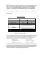
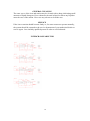
Instruction Manual
for
Intelligent Temperature Controlled
Soldering Station
LF-2000 (U)
For Lead-free soldering application and rework on professional SMD electronics.
1
INTRODUCTION
Thank you for purchasing Xytronic’s intelligent high power soldering station – the
best solution for your soldering equipment needs especially for lead free applications!
We believe that you will be more than satisfied with many features and the versatility
of your new soldering station. Please carefully read the instruction manual prior to
operate to maximize the advantages of using your new soldering station.
WARNING: This appliance is not intended for use by children or other persons
without assistance or supervision if their physical, sensory or mental capabilities
prevent them from using it safely. Children should be supervised to ensure that they
do not play with the appliance. Failure to observe the safety regulation will result in a
risk to life and limb. The manufacturer shall not be liable for damage resulting from
misuse of the unit or unauthorized alterations.
◆
◆
◆
◆
◆
CAUTION:
Always place the soldering iron in its original holder when not being used.
Keep the soldering tip and heating element away from the body, clothes and
flammable material when in operation.
The soldering tip and the heating element are still remaining hot after being
switched off. Ensure that you do not touch the soldering tip and the heating
element.
For your health, do not inhale solder fumes.
You must not undertake work on live parts. Only the technician is permitted to
undertake repairs. Use the original replacement part only.
KEY FEATURES
◆ HEATER/SENSOR FAILED DETECTION: If sensor circuit failed that the
display read “S--E” and cut off the heater power. If heater circuit failed the display
read “H--E” and cut off the sensor power.
◆ TEMPERATUE “LOCK-OUT” FEATURE: The temperature can be locked by
“password” code that is convenient for production line management.
◆ ISOLATED IRON HOLDER WITH TIP CLEANER: Made of low abrasive
brass shavings instead of conventional sponges to meet RoHS requirement cleans
better and no water is necessary.
◆ LOW VOLTAGE OUTPUT WITH SAFETY OPERATION: The power unit is
isolated from the A.C. line by a transformer and allows 32Vac to drive the heating
element. Solder wand runs from 32 Volts for safety and with 100W high power
ceramic heater for a super-fast heat-up and quick temperature recovery. The solder
wand is attached with heat resistant, non-burning, flexible 7-wires cord.
2
◆ ESD SAFE AND SPIKE FREE CIRCUITRY: The “Zero Voltage” electronic
switching design also protects voltage and current sensitive components (CMOS
devices, etc.) against damaging current and transient voltage spikes commonly
produced by less efficient, mechanically switched stations.
◆ DETACHABLE AC POWER CORD WITH PLUG: Engineered AC outlet for
alternating AC power cord with plug and connector specially designed for
individual CE countries requirements.
◆ EARTH JACK: With a grounding connector, there is the possibility for a
grounding of the wire strap if required.
◆ OPTIONAL SMD TWEEZERS : The additional feature is specially designed for
SMD chips, SOT, Flat pack ICs’ etc. reworking. TWZ120 Tweezers is equipped
with 32V/60W* 2 heaters which can be interchangeable with solder wand as an
option. Be sure before proceeding this operation, the main switch must be “OFF”
to avoid any damage to the unit.
PRODUCT DESCRIPTION
The high power LF-2000(U) electronically temperature controlled soldering station
with specially intelligent chip microcomputer control designs was developed to
meet the present and future Lead-free soldering needs of the electronic production
industry and suitable for work on professional SMD electronics. An ergonomic handle
with shorter distance between heating element and tip gets very fast heat up time and
quick heat compensation. A high-quality sensor and heat transfer technology ensure
precise temperature regulation is essential for making consistent, reliable soldered
connections. The aluminum alloy housing has the advantages of strong structure, good
heat sink and effectively resistant of electro-magnetic interference. It provides all the
benefits of temperature regulation and connects via a highly flexible burn-resistant
lead, and can be easily adjusted in temperature.
The LF-2000(U) incorporates electronic circuitry which enables the user to alter tip
temperature from 200 to 450℃ (392-842℉) without changing tips or heating
elements. Also, with bigger size digital display readout and pressing keys on the front
panel get clear vision and comfortable setting. The temperature is maintained within
+/-3℃ (+/- 6℉) of its operating temperature by a thermocouple sensor placed in the
head of the heating element, allowing the tip to rest against the sensor. The 100W high
power results in both a rapid heat-up and super fast recovery.
The revolutionary “Zero Voltage” electronic switching design also protects voltage
and current sensitive components (CMOS devices. etc.) against damaging current and
3
transient voltage spikes commonly produced by less efficient, mechanically switched
stations. The power unit is isolated from the A.C. line by a transformer and allows
only 32Vac to drive the heating element. The temperature “Lock-out” feature by
“password” is convenient for production management. The many features of the
product make it the ideal tool for service and repair technicians as well as production
line soldering operations. This unit is developed to meet the present and future
lead-free soldering needs of the electronic production industry and is ideal for use at
any AC outlet.
SPECIFICATIONS:
Model
Input
Output
Fuse (Slow type)
Temperature Range
Temperature Correction
Range
Default Set
Figure Dimension
Weight (Unit only)
LF-2000
220-240Vac 50Hz 100-120Vac 60Hz
32Vac/100W
T1A
T2A
200℃-450℃(392℉-842℉)
+99℃~-99℃/+178℉~-178℉
200℃/392℉
Temperature correction value“00”
111x158x137mm(W x H x D)
2.5kg
WORKING TEMPERATURE
To meet RoHS requirements, the 60/40 solder alloys are not allowed in the production
process. The lead free solder alloys require a working temperature of 30℃ ( 54℉ )
higher than previous generation electrical soldering. The working temperature of
solder is detailed below and can vary from manufacture to manufacture.
Melting point
220℃ (428℉)
Normal operation
300-360℃ (572-680℉)
Production line operation
360-410℃ (680-770℉)
When the iron’s working temperature is set within the parameters suitable for the type
of solder being used, a good joint is assured. Too low of a temperature will slow the
rate of solder flow while a high temperature setting might burn the flux in the solder
and emit a heavy, white smoke resulting in a dry joint or permanent damage to the
printed circuit board (P.C.B.) and may also shorten the tip life.
4
IMPORTANT: The temperature above 410℃ (770℉) is not recommended for
normal soldering functions, but can be used for short periods of time when high
temperatures are required. Please note that the lead free solder alloys require a higher
soldering temperature which shortens tip life.
OPERATING INSTRUCTIONS
● Ensure that the working voltage matches your power supply before beginning use.
● Check carefully for any damage during transportation.
● This unit contains:
1. Solder wand.
2. Iron holder with brass tip cleaner.
3. AC power cord with plug.
OPERATING PROCEDURES:
1. Ensure that the base unit power switch is in the “OFF” position.
2. Plug in Solder wand and connect AC power cord to mains “In-let”.
3. Turn “Mains power switch” to “ON” position.
4. Press the “▲” key up until the temperature to 250℃ (482℉). Then tin the surface
of the tip by applying a new covering of solder after being warmed to protect tip
and extend its life.
5. When the temperature reaches to the desired temperature that the heating indicator
light will be flashed on and off to maintain the set temperature. The unit now is
ready for use.
CAUTIONS:
REMEMBER, THE TIP IS HOT!
- The tip and barrel of the solder wand will cause serious burns if they are allowed
to contact skin. Always return the solder wand to the safety holder after each use.
DO NOT WORK ON LIVE CIRCUITS
- Before working on any mains powered equipment, make sure that it is turned off,
and the mains plug is removed from the power point.
DO NOT USE IF DAMAGED
- If the power lead becomes damaged or the soldering station becomes faulty,
discontinue use immediately. To comply with safety standards, the power lead
must only be replaced by authorized technicians as special purpose tools are
required.
Caution: Soldering irons operate at high temperatures and can easily burn
people or objects. Do not touch the tip and heater at any time and keep it a safe
distance from flammable materials while the unit is on or while it’s cooling.
Please allow a sufficient time for it to cool before changing tips or servicing the
unit!
5
TEMPERATURE SETTING: (No password set)
1. Increase temperature: By pressing “▲” key one time, the digital will be increase
“1” numeral. If pressing “▲” key over 2 seconds then the digital numerals will be
forwarded counting continuously till the temperature up to what you desire to set.
2. Decrease temperature: By pressing“▼” key, the same procedure as above.
PARAMETER SETTING:
1. Press “SET” key and hold for at least 4 seconds until display shown “— — —”
sign then release the “SET” key. The sign “— — —” starts to flash and reminding
the user to input the mode lock password “010” (fixed). If the user inputs the same
number as “010”, the unit will enter the modes selection procedure, otherwise,
the unit will be back from the current mode automatically.
2. After the unit enters the Modes selection, the LED will display “F-0”and flash.
Press “▲”or “▼” key to select modes. If the user doesn’t press “▲” or “▼” key
within 15 seconds or press “SET” key one time, then the unit will be mmediately
back from the Parameter Set status.
F-0 → F-1 → F-2 → F-3
↑
↓
←
←
←
←
3. Password Setting:
When the LED displays “F-1” and flashes, press “SET” key one time and the unit
enters the Password Set status. At this moment, the LED displays the pre-set value.
Press “▲” or “▼” key to change password set value. If the user sets “000” that
means the unit will be under the status of no password. If the user sets “100” then
means the unit will be under the password status. Press “SET” key once to finish
password setting and the unit will backup mode, the user can continue set other
modes or back from the setting mode.
For example:
4. Temperature Correction Setting
Press “SET” key once when the LED displays “F-2” and flashes that the unit
enters the Temperature Correction Mode. At this moment, the LED displays preset
correction value.
A: Operation of Centigrade temperature correction:
Press “▲” or “▼” key to change the temperature correction value. The first
digit “— ” means minus (actual temperature is down), “No display” means
plus (actual temperature is up).
B: Operation of Fahrenheit temperature correction value:
Press “▲” or “▼” key to change the temperature correction value. When
the numbers is sparkling on LED displays, it means minus value (actual
temperature falls), when the numbers stop sparkling, it means plus value (actual
6
temperature rises).
Press “SET” key once to finish the temperature correction and the unit
automatically backup mode. The user may continue set other modes or back from
the current setting mode.
Example for temperature correction: The current set temperature value is 200℃,
however, the actual temperature is only 190℃. So it needs to correct by +10℃.
Correction method: if the current correction value is 00 or -00; then change it to
10. If the current correction value is -20, then change it to -10. If the current
correction value is 20, then change it to 30.
5. Sleep Mode Set
Press “SET” key one time when the LED displays “F-3” and flashes, the unit
enters the Sleep mode status. At this moment, the LED displays the pre-set value.
Press “▲” or “▼” key to change the set value. If set value reads “000” that means
the unit set in “Sleep” mode releasing status. If the display read “100” that means
the unit set in “Sleep” mode. Press “SET” key once to finish the sleep mode
setting, then the unit automatically backup. The user may continue set other
modes or back from current set mode.
Please note the manufacturer original design will keep in “Free” status without
setting “Sleep” mode.
6. Wake-up method
① Temperature Down Suspend: If the unit set in Sleep mode function, after 20min
idleness, the system will enter the sleep mode automatically, the temperature will
go down to 200℃ and the LED displays at “ 200” and flashes. Activating the
solder wand will disengage the suspend status and the unit will immediately ramp
up to the preset temperature. There are three methods of wake-up the Temperature
Down Suspend.
a. Pick up the solder wand.
b. Press any key of the unit.
c. Turn off the main switch and restart.
② Power off Suspend: If the unit enters the Sleep mode over 40min without wake-up,
the unit will enter automatically the power off suspend status. It means the heater
power will be cut off and the LED displays “— — —” and flashes. The only way
to awake the power cut off mode is to switch off the main power and re
7
COMMON CAUSES OF TIP UNWETTING
1. Tip temperature higher than 410℃ (770℉).
2. The tip working surfaces are not tinned while the iron idling.
3. Lack of flux in soldering, wicking, repairing, and touch-up operations.
4. Wiping the tip on a high sulfur content, dirty or dry sponges and rags.
5. Touching with organic substances such as plastic, resin, silicone, grease or other
chemicals.
6. Impurities in solder and/or low tin content.
CARE OF TIPS
Caution: The soldering iron can reach very high temperatures. Be sure to turn
the unit off prior to carrying out any maintenance or trouble shooting steps listed
below.
IMPORTANT
Remove the tip and clean after moderate to heavy use or at least daily for light usage.
Remove any loose build up in the tip retaining assembly to prevent tip freezing.
The solder tips supplied are iron clad cooper and if used properly, they should
maintain optimum life.
1. Always tin the tip before returning it to the holder, turning off the station, or
storing it for long periods of time. Wipe the tip on a brass cleaner prior to use.
2. Keeping the iron set at high temperatures (more than 400℃or 750℉) will shorten
tip life.
3. Does not use excessive pressure to the tip or rub the joint with the tip while
soldering; it does not improve the heat transfer and may damage the tip.
4. Apply solder to the joint, not the tip when soldering. The flux is naturally caustic
and thus will eat away the tip.
5. Never clean the tip with a file or abrasive materials.
6. Do not use fluxes which contain chloride or acid. Use only rosin or resin activated
fluxes.
7. If an oxide film forms on the tip, it can be removed by careful buffing with a
600-800 grit emery cloth, isopropyl alcohol or equivalent and then wrapping rosin
core solder around the newly exposed surfaces. Coat the tinned areas with
rosin-core solder after the resin-core has melted.
8
NEW TIPS
Applying the following steps will lead to optimum life.
1. Set temperature to min. then turn the main power switch to the “ON” position.
2. Set temperature to 250℃ (482℉).
3. Coat the tinned surfaces with rosin-core solder after reaching 250℃ (482℉).
4. Set to desired temperature after allowing the unit to idle at 250℃ for 3 minutes.
5. The iron will be ready for use once it reaches the preset temperature.
IMPORTANT: Remove and clean the tip daily. If a new tip is installed, remove any
loose build up in the barrel assembly, otherwise the tip may fuse to the heating
element or retaining barrel.
SMD TWEEZERS OPERATION
For optional TWZ120 SMD Tweezers operations:
* Disconnect the soldering iron and change to TWZ120 Tweezers. Be sure the main
power switch is “OFF” before preceding this operation to avoid any damage.
* Use only the approximately designed tips for the job to avoid unnecessary
component damage.
* Gently pick up and remove components while ensuring that a vertical pick up and
pull out motion is maintained.
* Use the same procedure when reconnecting the solder wand.
Please note that the tweezers temperature will be lower about 50℃ than the soldering
iron temperature.
Drawing of Tweezers & spares SMD tips for TWZ120
MAINTENANCE
TIP MAINTENANCE AND DRESSING
Tips can be changed or replaced simply by unscrewing the knurled nut barrel
assembly. The station must be switched off and allowed to cool before this operation
as damage may result if the system is left on without the tip in place!
After removing the tip, blow out any oxide dust that may have formed in the tip
retaining area of the barrel. Be careful to avoid getting this dust in your eyes. Replace
the tip and screw back the knurled nut barrel assembly using only firm hand pressure
to tighten. Pliers should only be used to tighten the nut to avoid burning your fingers,
but care should be taken not to over-tighten as this could damage the element.
9
GENERAL CLEANING
The outer cover of the iron and station may be cleaned with a damp cloth using small
amounts of liquid detergent. Never submerse the unit in liquid or allow any liquid to
enter the case of the station. Never use any solvent to clean the case.
SERVICE
If the iron or station should become faulty or, for some reason not operate normally,
the system should be returned to the service department of your authorized dealer or
service agent. Or a similarly qualified person in order to avoid a hazard.
INTERCHANGEABLE TIPS
10