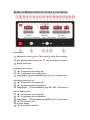
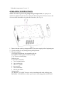
1
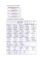
OPERATING MANUAL FOR LF-853D Multi-Function SMD Rework System INTRODUCTION Thank you for choosing XYTRONIC LF-853D Multi-Function S.M.D. Rework Station. This unit is the best tool for repairing work, combination with XYTRONIC LF-852D and LF-8800 which is specially designed for lead free soldering/desoldering, surface mount devices with temperature controlled hot air. The “3 in one” design ,save your working space. Please read the operating manual carefully to maximize the advantages of using your new LF-853D multi-function SMD rework station and keep this manual readily accessible for future reference. 【WARNING 】and 【CAUTION】 :: 【ELECTRICAL SHCOK 】 Warning and Caution are positioned at critical points in the manual to draw the user’s attention to significant safety concerns. Be sure to comply with the following warnings and cautions for your safety. This appliance is not intended for use by children or other persons without assistance or supervision if their physical, sensory or mental capabilities prevent them from using it safely. Children should be supervised to ensure that they do not play with appliance. Failure to observe the safety regulation will result in a risk of life and limb. The manufacturer shall not be liable for damage resulting from misuse of the unit or unauthorized alterations. 1. 2. 3. 4. 5. 6. 7. 8. Please unscrew the 4 screws under the bottom enclosure when the unit is used at the first time. (See the procedure on page13 ) Ensure the voltage rating of the unit and your power supply are identical prior to use. Check carefully of any damage during transportation. Put the product on a safe and stable working table. Table surface should be consisted of fire and heat resistant material due to the unit can reach very high temperature and potentially dangerous. During the operation, the heater is extremely hot, and will cause serious burns if contacted exposed skin. Use gloves and/or any heat resistant tools to pick up the PCB assembly to eliminate the possibility of burns. Do not use the product near combustible gases or flammable materials. Turn the power switch OFF and allow the heater to cool before checking or replacing heater and other parts, or prior to storing the unit. Keep the appliance clean. This may be used with a damp cloth using small amount of liquid detergent. Never submerse the unit in liquid or allow any liquid to enter the station. Never use any solvent to clean the case. 9. This unit is designed for soldering/desoldering, hot air SMD rework and should not be used for any other purpose without first consulting the manufacturer or its authorized agent. 10. Keep the unit out of the reach of children. Young children should be supervised to ensure that they do not play with the appliance. To prevent electrical shock, be sure to take the following precautions: 1. Make sure the unit is grounded. Always connect power to a grounded receptacle. 2. Do not pressure the AC power cord. Be sure the work area is well ventilated. 3. Do not bump, hit, pour water/liquids or otherwise subject the heating surface to physical shock. This may damage the heater. 4. To isolate the equipment from the mains before commencing repairs or making any maintenance to avoid electric shock. This may result in Death or serious injury. 5. Do not expose the unit to moisture nor use the unit with wet hands. 6. Turn the power switch off and remove the AC power cord by pulling the plug (not the cable) when the unit will remain unused for a longer period of time. 7. Do not modify the unit. Warning Soldering / Desoldering Function Warning ◆ Always place the soldering & desoldering irons in its original holder when not being used. ◆ Keep the soldering and desoldering tip and heating element away from the body, clothes and flammable material when in operation. ◆ The soldering and desoldering tip and the heating element are still remaining hot after being switched off. Ensure that you do not touch the tips and the heating elements. ◆ For your health, do not inhale solder fumes. ◆ You must not undertake work on live parts. Only the technician is permitted to undertake repairs. Use the original replacement part only. Hot Air Function Warning ● To last the life of the heating element, not recommend continuously using at low air flow and high temperature. Let the heating element be cooler after using a maximum 20 minutes. Ensure that it is placed back on its cooling stand to cool down between rework operations. Also, do not switch the hand tool on while it is in the cooling stand. Fail to comply with the instructions may result in damage to the hand tool. ● Do not aim the hot air at your eyes. Do not allow the hot air from the hand tool to aim the eyes as serious eye damage may occur. ● The hot air pencil can produce a lot of heat. Do not allow the heater and the nozzle to contact exposed skin as burning may occur. To eliminate the possibility of burns, allow time for the equipment to cool before commencing maintenance. ● Death or serious injury may result from electric shock. It is therefore essential to isolate the equipment from the mains before commencing repairs. ● Keep the hot air away from the body, clothes and flammable material when in operation. The nozzle metal is in a high temperature status, do not touch the nozzle! Always replace the hand tool to its original holder when not being use. The nozzle and the heating element are still remaining hot after being switched off. Ensure that you do not touch them. ● Do not block the air outlet in full area of the nozzle, or it may cause the heat reflection and damage the heating element. ● Do not leave when the machine is on operating: Stare at the nozzle when the rework station is on operating, so as not to burn your body or other objects. Turn off the machine and unplug the power cord when you are leaving and put the hot air handle to the holder in one side of the machine. The nozzle is still remaining hot after being switch off on some time. Ensure that you do not touch the nozzle. ● Do not use if damaged: If the pump doesn’t work or the rework station becomes faulty, discontinue using immediately. To comply with safety standards, the pump or other part must only be replaced by authorized technicians as special purpose tools are required. Only the technician is permitted undertake repairs. Use the original replacement part only. ● Remember unplug in the power cord: The station must be switched off and the power cord must be unplug-in before replacing the fuse in AC socket in rear side of the machine. ● Do not unplug the power cord; when the power switch is turned off, the cooling system will begin to work automatically, the temperature falls down to 100℃(212 ℉) to protect the heater, remember that do not unplug the power cord at this time until the unit stop working. PRODUCT FEATURES ◆ “3 in one” by design, saving working space, owning three function, can greatly meet the users need. ◆ With special intelligent chip microcomputer control design, double LED display operating by pressing keys, make it convenient and comfortable operation. ◆ Selection free for Fahrenheit and Centigrade (Celsius) temperature. ◆ “Password selection”: Temperature or air blow by digital display readout, easy to read. The temperature can be locked by “password” code that is convenient for production line management. Soldering / Desoldering Function ◆ HEATER/SENSOR FAILED DETECTION: If sensor circuit failed that the display reads “S--E” and cut off the heater power. If heater circuit failed the display will read “H--E” and cut off the heater power. ◆ TEMPERATUE “LOCK-OUT” FEATURE: The temperature can be locked by “password” code that is convenient for production line management. ◆ ESD SAFE AND SPIKE FREE CIRCUITRY: The “Zero Voltage” electronic switching design also protects voltage and current sensitive components (CMOS devices, etc.) against damaging current and transient voltage spikes commonly produced by less efficient, mechanically switched stations. ◆ DELAYED SUCTION: To eliminate the problem of solder clogging up the tip, a delayed switch feature has been incorporated for the unit that allows the pump to continue sucking for 1.5 seconds after the actuator switch is released. ◆ LIGHTWEIGHT SOLDERING IRON: Ergonomic mini handle that stays cool and prevents operator fatigue. ◆ ENERGY SAVER MODE: If the station has been idle for 20 minutes, the energy saver feature will automatically engage, the temperature goes down to 150℃ from the set temperature for Soldering and 200℃ from the set temperature for de-soldering Activating the solder/desolder wands will disengage the power saving feature and the unit will immediately ramp up to the preset temperature. When over 40 minutes without operation the main power will be switched off to “sleep mode” which cuts power consumption and extends tip life. Please note: You have to turn off the power switch first and then switch “ON” again to commence work when the unit goes to “Sleep” mode. ◆ IRON WORKING OPTION: When the users don’t use the soldering or desoldering function ,or they also set by pressing keys “ SET + ▲”,at this time, the iron which you set will enter the power off suspend status. It means that the heater power is cut off. If press “▼"then the heater power will be on. ◆ OPTIONAL SMD TWEEZERS : The additional feature is specially designed for SMD chips, SOT, Flat pack ICs’ etc. reworking. TWZ100 Tweezers can be interchangeable with soldering iron as an option. Be sure before proceeding this operation, the main switch must be “OFF” to avoid any damage to the unit. Hot Air Funciton ◆ With the high power heating element, heat up quickly, the momentary power can reach 600W. ◆ Temperature adjustable, suits for removing QFP, SOP, PLCC or SOJ chips etc., especially the built in static free circuit design is safety for the sensitive elements like CMOS ICs. ◆ SENSOR /PUMP FAILED DETECTION: If sensor circuit failed that the display read “S--E” and cut off the heater power. If the pump circuit failed that the display read ”P-E” and cut off the heater power. ◆ Auto-cooling design: When the power switch off, the cooling system will begin to work automatically, the temperature falls down to 100℃(212℉) to protect the heating element from burning .. ◆ Heating element auto-protecting function: When heating element reaching a high temperature which can be protected automatically, to lasting the life of heating element. SPECIFICATIONS MODEL Power Voltage Fuse (Fast type) LF-853D multi-functon SMD rework system 220-240Vac 50Hz/ 100-120Vac 60Hz 10A(Fast type) 15A(Fast type) Power Consumption (Max) 900W Weight 12kg Power Consumption 100W Temperature range SIA:150℃-480℃(302℉-896℉) Sleep Temperature 150℃(302℉) Temperature correction range +99℃~-99℃/+178℉~-178℉ 150℃(302℉) Soldering F-1: “000” Default seting F-2:“00” F-3:“000” F-4:“℃” Power Consumption Temperature range Sleep Temperature Temperature correction range Desoldering 170W DIA: 300℃-450℃(572℉-842℉) 200℃(392℉) +99℃~-99℃/+178℉~-178℉ 300℃ (572℉) F-1: “000” Default seting F-2:“00” F-3:“000” F-4:“℃” Hot Air Power Consumption 600W Air Flow 1.5 L / Min -40L / Min Temperature range 100℃-480℃/212℉-896℉ Air range 10-99 F-1:“000” Default seting F-2“℃” Temperature100 Air 10 BRIEF INTRODUCTION OF PANEL FUNCTIONS: Front panel 1 Main power switch ○ 2 SIA /TWZ socket○ 3 HAP: Hot air fitting ○ 4 DIA: Desolder/HAP wand socket ○ 5 VAC: Desoldering vacuum ○ 6 Hot air pencil inlet ○ Soldering Function Part 7 “▲”: Temperature increasing (UP) ○ 8 “▼”: Temperature decreasing (Down) ○ 9 Temp Display ○ 10 Heat indicating light ○ 11 “SET”: Function key ○ Desoldering Function Part 12 “▲”: Temperature increasing (UP) ○ 13 “▼”: Temperature decreasing(Down) ○ 14 Temp Display ○ 15 Heat indicating light ○ 16 “SET”: Function key ○ Hot Air Function Part 17 “▲”: Temperature increasing (UP) ○ 18 “▼”: Temperature decreasing(Down) ○ 19 Temp Display ○ 20 Heat indicating light○ 21 “SET”: Function key ○ 22 “▲”: Hot air blow (UP) ○ 23 Air blow display ○ 24 “▼”: Hot air blow (DOWN) ○ FUNCTION INTRODUCTION Soldering /desoldering function introduction (Both soldering and desoldering function can be set in the same way.) TEMPERATURE SETTING: (No password set) 1. Increase temperature: By pressing “▲” key one time, the digital will be increase “1” numeral. If pressing “▲” key over 2 seconds then the digital numerals will be forwarded counting continuously till the temperature up to what you desire to set. 2. Decrease temperature: By pressing“▼” key, the same procedure as above. PARAMETER SETTING: 1. Press “SET” key and hold for at least 5 seconds until display shows“— — —” sign then release the “SET” key. The sign “— — —” starts to flash and reminding the user to input the mode lock password “010” (fixed). If the user inputs the same number as “010”, the unit will enter the modes selection procedure, otherwise, the unit will be back from the current mode automatically. 2. After the unit enters the Modes selection, the LED will display “F-0”and flash. Press “▲”or “▼” key to select modes. If the user doesn’t press “▲” or “▼” key within 15 seconds or press “SET” key one time, then the unit will be immediately back from the Parameter Set status. For example: F-0 → F-1 → F-2 → F-3 →F-4 ↑ ↓ ← ← ← ← ← 3. Password Setting: When the LED displays “F-1” and flashes, press “SET” key one time and the unit enters the Password Set status. At this moment, the LED displays the pre-set value. Press “▲” or “▼” key to change password set value. If the user sets “000” that means the unit will be under the status of no password. If the user sets “100” then means the unit will be under the password status. Press “SET” key once to finish password setting and the unit will backup mode, the user can continue set other modes or back from the setting mode. 4. Temperature Correction Setting: Press “SET” key once when the LED displays “F-2” and flashes that the unit enters the Temperature Correction Mode. At this moment, the LED displays preset correction value. A: Operation of Centigrade temperature correction(+99℃~-99℃): Press “▲” or “▼” key to change the temperature correction value. The first digit “— ” means minus (actual temperature is down), “No display” means plus (actual temperature is up). B: Operation of Fahrenheit temperature correction value(+178℉~-178℉): Press “▲” or “▼” key to change the temperature correction value. The first digit “— ” means minus (actual temperature is down), “No display” means plus. Press “SET” key once to finish the temperature correction and the unit automatically backup mode. The user may continue set other modes or back from the current setting mode. Example for temperature correction: The current set temperature value is 300℃, however, the actual temperature is only 290℃. So it needs to correct by +10℃. Correction method: if the current correction value is 00 or -00; then change it to 10. If the current correction value is -20, then change it to -10. If the current correction value is 20, then change it to 30. 5. Sleep Mode Set: Press “SET” key one time when the LED displays “F-3” and flashes, the unit enters the Sleep mode status. At this moment, the LED displays the pre-set value. Press “▲” or “▼” key to change the set value. If set value reads “000” that means the unit set in “Sleep” mode releasing status. If the display read “100” that means the unit set in “Sleep” mode. Press “SET” key once to finish the sleep mode setting, then the unit automatically backup. The user may continue set other modes or back from current set mode. Please note the manufacturer original design will keep in “Free” status without setting “Sleep” mode. 6. Wake-up method: ① Temperature Down Suspend: If the unit is set at Sleep mode function, after 20min idleness, the system will enter the sleep mode automatically, the temperature of soldering will go down to 150℃ (302℉) / and the LED displays at “ 150” and flashes, the temperature of desoldering will go down to 200℃ (392℉) and the LED displays at “ 200” and flashes. Activating the solder wand will disengage the suspend status and the unit will immediately ramp up to the preset temperature. There are three methods to wake-up the Temperature Down Suspend. a.Ⅰ Soldering: Pick up the solder wand 210ESD and shake it gently. Ⅱ Desoldering: Pick up the solder wand and press the red suction button on the DIA 100. b. Press any key of the unit. c. Turn off the main switch and restart. 2 ○ Power off Suspend: If the unit enters the Sleep mode over 40min without wake-up, the unit will enter automatically the power off suspend status. It means the heater power will be cut off and the LED displays “— — —” and flashes. You can wake it up by pressing “▼” key when you reuse the iron or turn off the main switch and re-switch on. 7. Fahrenheit and Centigrade (Celsius) temperature selection When temperature display window shows "F-4" and blinking, press the "SET" button, at this time ,the system enters the degrees Fahrenheit and Centigrade temperature selection function, indicating the temperature of the window shows the current status. Press "▲" or "▼" key to change the temperature selection status. It expressed as degrees Celsius temperature value if set to “℃"; it shows as degrees Fahrenheit temperature if set to ℉ WORKING TEMPERATURE SOLDERING To meet RoHS requirements, the common 60/40 lead solder alloys are not allowed in the production process. Lead free solder alloys require a working temperature of 30℃ (54℉) higher than previous generation electrical soldering. The working temperature of solder is detailed below and can vary from manufacture to manufacture. Melting point Normal operation Production line operation 220℃ (428℉) 300-360℃ (572-680℉) 360-410℃ (680-770℉) When the soldering iron’s working temperature is set within the parameters suitable for the type of soldering being used, a good joint assured. Too low of a temperature will slow the rate of solder flow while a high temperature setting might burn the flux in the solder and emit a heavy, white smoke resulting in a dry joint or permanent damage to the printed circuit board (P.C.B) and may also shorten tip life. IMPORTANT: The temperature above 410℃ (770℉) is not recommended for normal soldering functions, but can be used for short periods of time when high temperatures are required. DESOLDERING Recommended tip working temperatures are detailed below and can vary from joint to point. Operation for small joint 320℃ - 360℃ (608℉- 680℉) Operation for larger joint 370℃ - 400℃ (698℉- 752℉) Too low of a temperature will slow the flow rate of solder and may clog the tip. Too a high temperature may burn the P.C.B. Hot air function introduction TEMPERATURE SETTING: (No password set) 1. Increase temperature: By pressing “▲” key one time, the digital will be increase “1” numeral. If pressing “▲” key over 2 seconds then the digital numerals will be forwarded counting continuously till the temperature up to what you desire to set. 2. Decrease temperature: By pressing“▼” key, the same procedure as above. AIR FLOW SETTING: (No password set) 1. Increase temperature: By pressing “▲” key one time, the digital will be increase “5” numeral. If pressing “▲” key over 2 seconds then the digital numerals will be forwarded counting continuously till the temperature up to what you desire to set. 2. Decrease temperature: By pressing“▼” key, the same procedure as above. PARAMETER SETTING: 1. Press “SET” key and hold for at least 3 seconds until display shows“— — —” sign then release the “SET” key. The sign “— — —” starts to flash and reminding the user to input the mode lock password “010” (fixed). If the user inputs the same number as “010”, the unit will enter the modes selection procedure, otherwise, the unit will be back from the current mode automatically. 2. After the unit enters the Modes selection, the LED will display “F-0”and flash. Press “▲”or “▼” key to select modes. If the user doesn’t press “▲” or “▼” key within 15 seconds or press “SET” key one time, then the unit will be immediately back from the Parameter Set status. For example: F-0 → F-1 → F-2 ↑ ↓ ← ← ← 3. Password Setting: When the LED displays “F-1” and flashes, press “SET” key one time and the unit enters the Password Set status. At this moment, the LED displays the pre-set value. Press “▲” or “▼” key to change password set value. If the user sets “000” that means the unit will be under the status of no password. If the user sets “100” then means the unit will be under the password status. Press “SET” key once to finish password setting and the unit will backup mode, the user can continue set other modes or back from the setting mode. 4. Fahrenheit and Centigrade (Celsius) temperature selection When temperature display window shows "F-4" and blinking, press the "SET" button, at this time, the system enters the degrees Fahrenheit and Centigrade temperature selection function, indicating the temperature of the window shows the current status. Press "▲" or "▼" key to change the temperature selection status. It expressed as degrees Celsius temperature value if set to ℃; it shows as degrees Fahrenheit temperature if set to ℉. OPERATING INSTRUCTIONS NOTE: In order to protect the pump during transportation, the pump in the machine is tightened by the 4 screws under the bottom enclosure. Please unscrew the 4 screws when the machine is used at the first time. (See Fig. A). Fig. A 1. Ensure that the working voltage matches your power supply before beginning use. 2. Check carefully for any damage during transportation. 3. This unit contains: A: DIA100: Desoldering iron assembly with tip. B: 210ESD: Soldering iron assembly with tip.. C: AC Power cord with plug. D:Hot air gun E:Accessories included: a. Two cleaning brushes b. One cooling strip c. One 0.7∮ probe d. 4pcs nozzles e. Two iron holders f. Hot air gun holder Optional parts: A) TWZ100: 32V/100W Tweezers can be interchangeable with soldering iron. B) HAP80: 32V/80W Hot air blow pencil can be interchangeable with DIA100. OPERATING PROCEDURES Caution: Check carefully for any damage during transportation and ensure that the working voltage matches your power supply before plugging in the station. 1. Ensure that the base unit’s power switch is in the ‘OFF” position. 2. Plug in “Solder and Desolder” wands, connect “Vacuum tube” to “VAC”. Put the hot air gun to the (holder) 3. Connect AC power cord to mains “In-Let”. 4. Turn switch “ POWER SWITCH” to “ON” position and the switch led will be light. 5. All of the functions ( Soldering ,Desoldering,Hot air gun )will work at the same time after turning the power switch , and then the corresponding temperature LED or wind LED display will be ON and show the value. 6. Users can turn off the the Soldering function or Desoldering function by pressing the key”SET+UP” ,then the corresponding LED display will show “_ _ _”. NOTE: It means that the corresponding heater power is cut off.At this time ,the users can only use the hot air function. Pressing on the “▲”on can reuse the corresponding function. A: Soldering function / Desoldering function option 1) Press the “▲” key up until the temperature to 250℃ (482℉) (If set to degrees Centigrade, the temperature display window of the upper right corner shows ℃, if set to degrees Fahrenheit, the temperature display window of the upper right corner shows ℉). 2) Then tin the surface of both soldering and desoldering tips by applying a new covering of solder to protect it. 3) You can set the desired temperature setting by pushing the “up” or “down” key. When the temperature reaches to the desired temperature that the heating indicator light will be flashed on and off to maintain the set temperature. The unit now is ready for use. CUATION: Do not touch any of the irons at any time while the unit is on or while it’s cooling as they will still be hot. IMPORTANT DESOLDERING 1. Only activate the vacuum after the solder has completely melted. Melting is accomplished by moving the hot tip around the lead leaving visible melted solder on the component side of the P. C. B. See Fig. 1 & 2. FIG-1 2. 3. 4. 5. 6. 7. 8. FIG-2 Release the vacuum switch only alter the solder on the tip has been removed, otherwise the tip may clog. Add solder to the joint of the component and allow the solder to melt completely for improved desoldering. Remove the solder collector and clean it after no more than 200 applications. However, daily cleaning is strongly recommended. Replace the cotton pad in the solder collector and the in-line filter when they begin to turn yellow. If there is insufficient vacuum, use the spring wire included to clean the tip and also check he in-line filters. Be sure that all filters are in place during operation or damage to the vacuum pump may occur. Follow the steps outlined in the OPERATIOING PROCEDURE section of this manual if a new tip is to be installed. COMMON CAUSES FOR TIP UNWETTING 1. Tip temperatures higher than 410℃ (770℉). 2. The tip working surfaces are not tinned while the iron idling. 3. Lack of flux in soldering, wicking, repair, and touch-up operations. 4. Wiping the tip on a high sulfur content, dirty or dry sponge. 5. Contact with organic substances such as plastic, resin, silicone, grease and other chemicals. 6. Impurities in the solder and/or low tin content. CARE OF TIPS CAUTION: The soldering, desoldering irons can reach very high temperature. Be sure to turn the unit off prior to carrying out any maintenance or trouble shooting steps listed below! IMPORATNT: Remove the tip and clean after each moderate to heavy use or daily for light usage. Remove any loose build up in the tip retaining assembly to prevent tip freezing. Both solder, desolder tips supplied are iron clad copper and if used properly should maintain optimum life. 1. Always tin the tip before returning it to the holder, turning off the station, or storing it for long periods of time. Wipe the tip on a brass cleaner prior to use. 2. Keeping the iron set at high temperatures (more than 400℃ or 752℉) will shorten tip life. 3. Do not use excessive pressure on the tip or rub the joint with the tip while soldering and/or desoldering; it does not improve the heat transfer and may damage the tip. 4. Apply solder to the joint, not the tip when soldering. The flux is naturally caustic and thus will eat away the tip. 5. Never clean the tip with a file or abrasive materials. 6. Do not use fluxes which contain chloride or acid. Use only rosin or resin activated fluxes. 7. If an oxide film forms, it can be removed by careful buffing with 600-800 grit emery cloth, isopropyl alcohol or equivalent and then the tinned areas with rosin-core solder after the resin-core has melted. NEW TIPS Applying the following steps give the tip optimum life. 1. Set both temperatures to min. then turn the main power switch to the “ON” position. 2. Set soldering tip temperature to 250℃ (500℉ approx.) and desoldering tip temperature to min. Coat the tinned surfaces with rosin-core solder after reaching 250℃. 3. Set to the desired temperature about 3 minutes after being warmed that the station will be ready for sue once it reaches preset temperature. IMPORTANT: Remove and clean the tip daily. If a new tip is installed, remove any loose build up in the barrel assembly, otherwise the tip may fuse to the heating element or retaining barrel. METHOD TO CHECK FOR LOSS OF SUCTION The following procedures should be used on DIA100 to check whether loss of suction is due to the tip, solder collector, tube or in-line filter. CAUTION: THE DESOLDER SWITCH MUST BE “OFF” AND ALLOW THE IRON TO COLL BEFORE ATTEMPTING THE FOLLOWING PROCEDURES: 1. Disconnect vacuum tube form the fitting on the front panel, place finger over the hole of the fitting, depress vacuum switch and you should have a strong vacuum. If not, send back to your nearest service center for pump repair. 2. Disconnect the inline filter from the iron assembly, depress vacuum switch, replace filling of the in-line filter if there is little vacuum pressure or the filters are discolored. 3. Remove solder collector from desolder iron assembly, place finger over the hole of the collector, depress vacuum switch. There is little suction clean or replace the collector tube. 4. Depress vacuum witch, clean the tip tube with spring wire provided if there is no suction per the “Procedure for Cleaning Clogged Tip” section below. B: Hot air function option OPERATING PRECAUTIONS 1. Make sure both heater and nozzle are cool before attaching the nozzle. 2. Caution High Temperature Operation Both nozzle and hot air are extremely hot and can cause burns. Never touch the nozzle and heater assembly or allow the hot air to blow against your skin. Initially, the iron may emit white smoke, but this will soon dissipate. 3. Be sure to cool the unit after using. While the power switch off, the unit will automatically blow cooling air through the pipe for a short period of time. Do not disconnect the plug during this cooling process. 4. Do not disassemble the pump. If the pump or other critical internal components become faulty, discontinue its use immediately. Please return to your vendor or its authorized repairers for proper servicing. 5. Disconnect the plug while the unit is not in use. When the power cord is connected into the power supply, the unit has a little flow of electricity; even the Power Switch is in off position. So when you don’t use the unit for a longer period of time, disconnect the plug. Operation Setup 1. Select the Nozzle that matches the size of the IC. Attach the nozzle when both heating element and the nozzle are cool and the unit is turned off and unplugged. 2. Loosen the screw on the nozzle and attach nozzle. 3. Press “▲” or“▼”key on the hot air function panel to choose the desired temperature or air flow. 4. Press “▲”or “▼” key to choose the desired air flow on the right side of the front panel. The speed will change 5 degrees by pressing the keys “▲” or“▼” at a time. 5. After adjusting the air flow and temperature and wait for the temperature to stabilize for a short period of time. IMPORTANT: Do not force the nozzle or pull on the edge of the nozzle with pliers. Also, do not tighten the set-screw too tightly. Suitable for desoldering of SMD components such as SOIC, CHIP, QFP, PLCC, BGA etc. QFP De-soldering 1. Melt the solder: Hold the iron so that the nozzle is located directly over, but not touching the IC and allow the hot air to melt the solder. Be careful not to touch the leads of the IC with the nozzle. 2. Remove the IC: Once the solder has melted, remove the IC by lifting the pliers. 3. Turn the power switch off: After the power switch is off, an automatic blowing function begins sending cool air through the pipe in order to cool both the heating element and the handle. So do not disconnect the plug during this cooling process. 4. In case you don’t use the unit for a long time, disconnect the plug. Note: After the power switch off about one minute later, the temperature will fall down to 75℃ (167℉) and power automatically shut off. 5. Remove any remaining solder: After removing the IC, cleaning the remaining solder chips with a wick or desoldering tool. Note: For SOP, PLCC etc. would recommend by using tweezers iron to desolder. QFP Soldering 1. Apply the solder paste: Apply the proper quantity of solder paste and flux (preferably no-clean) and place install the SMD on the PCB. 2. Preheat SMD. 3. Soldering: Heat the lead frame evenly. 4. Washing: When soldering is completed, wash the area with a defluxer. Note: While there are many advantages of hot air SMD rework, it is also possible to have defects for soldering BGA. Will recommend to inspect all soldering joints closely. MAINTENANCE DESOLDER TIP REPLACEMENT AND DRESSING Desolder tips can be changed or replaced simply unscrewing the barrel nut assembly. The station must be turned off and allowed to cool before this operation. If the system is left on without a tip in place, damage to the iron assembly may occur! After removing the tip, blow out any oxide dust that may have formed in the tip receptacle. Be careful not to get dust in your eyes. Replace the tip according to Figures 3-9 and hand tighten the securing screw for the barrel nut assembly. Pliers can be used to avoid contact with hot surfaces BUT SHOULD BE USED WITH CAUTION because over tightening may cause damage to the element or fuse the tip to the element. PROCEDURE FOR CLEANING CLOGGED TIPS CAUTION: This procedure is to be working in high temperature. Be careful to avoid burning your fingers during this operation. 1. Be sure that the spring wire (included) will not go through the nozzle of the desolder tip. 2.Adjust the heating element to a higher temperature allowing the clogged solder to melt. Clean the tip by sliding the spring wire up and down until the passage is clear. (See Fig. 3) 3.Unscrew the barrel nut assembly as in Figures 4 & 5. FIG-4 FIG-5 4.Remove the tip by using a pliers as in Figures 6 & 7. FIG-6 FIG-7 5.Insert the stainless tube of the tip back in the barrel to melt the solder in around 5 seconds as in Figure 8. FIG-8 FIG-9 6.Remove again and shake out any loose melted solder in the tip per Figure 9, the tip should now be unclogged. Replace the tip and screw back the retaining barrel nut assembly but care should be taken not to over tighten! PROCEDURES FOR CLEANING THE SOLDER COLLECTOR CAUTION: The desolder switch must be turned “OFF” and the iron allowed to cool before this operation. 1. Hold iron as in Figure 10. Press and turn the red knob at the butt of the iron. FIG-10 2. Slide out the solder collector as in Figure 11. (CAUTION: The solder collector is glass and thus retains heat, handle with care!) FIG-11 3. Point the collector down while shaking slightly (see Figure 12.) and the waste solder will fall out. This task must be carried out periodically for proper operation of the station. FIG-12 4. Remove cooling strip with a pair of long nose pliers or tweezers. (see Figures 13 & 14) FIG-13 FIG-14 5. Clean the cooling strip and glass collector with wire brush (included). PROCEDURE FOR REPLACING FILTERS SOLDER COLLECTOR FILTERS 1. Be sure the iron/filter assembly have cooled. 2. Hold iron as in Figure 10, press/turn red knob on the butt of iron. 3. Remove solder collector (see Figure 11). 4. Disassemble the solder collector into 2 pars (see Figures 15 & 16). FIG-15 FIG-16 5. Remove old cotton filter and replace (see Figures 17 & 18). FIG-17 FIG-18 IN LINE FILTERS 1. Unscrew in line filter (see Figure 19) and then pull apart (Figure 20). FIG-19 FIG-20 MAINTENANCE NOTE FOR DIA100 Change of Cotton Filament (76-1411030): Please note that the cotton filament cannot be washed with the water. Water drops would be sucked into the Pump and may cause the pump damaged within 1 to 2 months. If you wash with the water, Cotton filament will turn solid and will stop the DIA100 working well. Please change at least once 3 to 5 days if you use 8 hours per day. Change of Charcoal Filter (78-151500): Charcoal filter will turn solid if you wash with the water. If you use 8 hours per day that the Charcoal filter has to be changed within 3 weeks. On the other hand, if you wash the Charcoal filter and do not dry properly, water drops will be sucked into the Pump and may cause the pump damaged easily. Change of Glass Solder Collector (75-160110): Glass solder collector will be broken easily if the client knocked the DIA100 against the desktop. The glass collector also needs to be changed every 3 to 5 months usage. Maintenance for Desoldering Heater and Tip: To prevent the desoldering tip being stuck by solder, the desoldering tip has to be cleaned by a Probe after every time usage. In such ways, desoldering tip’s life can be lasting longer. Desolder Heater would be probably broken when you remove the desoldering tip with a pliers careless in hot condition. Slightly remove the tip with pliers or may use the anti-rusty cleaner when the tip clogged with the heater and do not forced open. Please read the “Procedure for Cleaning Clogged Tips” carefully on page18 on the manual. PROCEDURE FOR REPLACING HOT AIR GUN HEATING ELEMENT Caution :The main swich must be “off” and allow the iron to cool before attemptling the following procedure 1.Unscrew the 3 screws on handle then take out the handle cover.(See Fig.1 below) 2.Disconnect the grounding wire jack and pull the heating element out from the stainless steel tube. Important: Do not damage or loss the quartz glass and /or insulation mica inside of the stainless steel tube. (See Fig.2 below ) 1. Pull the default heater off and replace a new one then re-assembly the heater according the backward procedure. (See Fig.3) SPARE PART Part No. 79-460012 Heating element 120Vac,60Hz,600W Part No.79-560012 Heating element 230-240Vac,50Hz,600W INTERCHANGEABLE ACCESSORY 1.INTERCHANGEABLE TIPS Soldering tips for SIA :210ESD Desoldering tips for DIA: DIA100 2.INTERCHANGEABLE NOZZLES