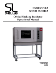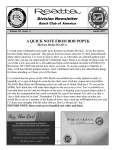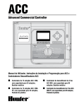
1
SSI5 SSI5-2 SSI5R SSI5R-2 Orbital Shaking Incubator Operational Manual Models: SSI5 SSI5-2 SSI5R SSI5R-2 Previously designated as SI6 SI6-2 SI6R SI6R-2 4861534 11/2013 SHEL LAB SI6/SI6R Shaking Incubator Operational Manual Table of Contents Using the Unit Safely 4 Introduction ..................................................................................................................... 4 General Safety Considerations ........................................................................................ 4 Precautions for Your Unit ............................................................................................... 4 Meanings of Symbols ..................................................................................................... 5 About this Manual........................................................................................................... 5 Features of Your Unit 6 Product description ......................................................................................................... 6 Key Features ................................................................................................................... 6 Receiving Your Unit 7 Unpacking and Inspecting Your Unit ............................................................................. 7 Inspection Guidelines.................................................................................................. 7 Recording Data Plate Information .................................................................................. 7 Installing the Unit 8 Installation Overview ...................................................................................................... 8 Selecting a Location for the Unit .................................................................................... 8 Leveling the Unit ............................................................................................................ 8 Sterilizing Your Unit....................................................................................................... 8 Installing Sample Tray .................................................................................................... 9 Plugging the Unit into a Power Source ........................................................................... 9 Operating the Unit 10 Control Panel Overview ................................................................................................ 10 Getting the Unit Ready for Use .................................................................................... 10 Turning the Unit On ...................................................................................................... 10 Setting the Chamber Temperature ................................................................................ 11 Calibrating the Main Temperature Control................................................................... 11 Setting the Shaker Speed .............................................................................................. 11 Using the Timer ............................................................................................................ 12 Setting the Safety Temperature Alarm ......................................................................... 12 Adding or Removing Counterweights .......................................................................... 12 Adjusting the Shaker Movement .................................................................................. 13 Interior Accessory Outlet .............................................................................................. 14 Maintaining the Unit 15 Disinfecting Your Unit ................................................................................................. 15 A Typical Decontamination Procedure ......................................................................... 15 Control Maintenance ..................................................................................................... 15 Troubleshooting 16 Solving Problems .......................................................................................................... 16 Temperature .................................................................................................................. 16 Refrigeration (SI6R models only) ................................................................................. 18 Power ............................................................................................................................ 18 Mechanical .................................................................................................................... 19 Contamination ............................................................................................................... 19 Getting Your Unit Serviced 20 2 SHEL LAB SI6/SI6R Shaking Incubator Operational Manual Table of Contents Getting Assistance ........................................................................................................ 20 Obtaining Nameplate Information ................................................................................ 20 Returning Your Unit ..................................................................................................... 20 SHEL LAB Contact Information .................................................................................. 20 Replacement Parts and Accessories 21 Replacement Parts ......................................................................................................... 21 Specifications 22 These units are TUV CUE listed as orbital shaking incubators for professional, industrial, or educational use where the preparation or testing of materials is done at approximately atmospheric pressure and no flammable, volatile, or combustible materials are being heated. These units have been tested to the following requirements: CAN/CSA C22.2 No. 61010-1:2012 CAN/CSA C22.2 No. 61010-2-010 + R:2009 UL 61010-1:2004 + R:2005-07 + R:2008-10 UL 61010A-2-010:2002 UL 61010-1:2012 EN 61010-1:2010 EN 61010-2-010:2003 3 SHEL LAB SI6/SI6R Shaking Incubator Operational Using the Unit Safely Introduction Thank you for choosing a SHEL LAB shaking orbital incubator. SHEL LAB sets the standard for quality and reliability. Your unit is backed by over 30 years of design and manufacturing excellence in the scientific, research, and medical equipment industries. Your unit is a general-purpose incubator designed for professional, industrial or educational use where the preparation or testing of materials is done at approximately atmospheric pressure, and no flammable, volatile or combustible materials are being heated. These units are not intended for use at hazardous or household locations. Do not connect the unit to a power source of any other voltage or frequency beyond the range stated on the power rating overlay at the rear of the unit. Do not modify the power cord provided with the unit. If the plug does not fit an outlet, have a proper outlet installed by a qualified electrician. Avoid damaging the power cord. Do not bend it excessively, step on it, place heavy objects on it. A damaged cord can easily become a shock or fire hazard. Never use a power cord after it has become damaged. Precautions for Your Unit Before you use the unit, read this entire manual carefully to understand how to install, operate, and maintain the unit in a safe manner. Your satisfaction with the unit will be maximized as you read about its safety and operational features. Keep this manual on-hand so it can be used by all operators of the unit. Be sure all operators of the unit are given appropriate training before you put the unit in service. Observe the following additional safety guidelines for your unit. Use the unit only in the way described in this manual. Failure to follow the guidelines and instructions in this manual may be dangerous and illegal. General Safety Considerations Operating Conditions For optimum performance, use your incubator at room temperatures between 18 and 25C, at no greater than 80% relative humidity (at 25C). If you intend to operate the unit in conditions outside of these limits, contact customer service. Installing the Unit Installation of the unit can be performed by the end user Lifting and Handling The incubator is heavy and should be moved by a lifting device, such as pallet jack. If you must lift the device by hand, always observe the following guidelines: Your incubator and its recommended accessories have been designed and tested to meet strict safety requirements. For continued safe operation of your incubator, always follow basic safety precautions including: o Do not move the incubator while it is plugged into the power source. Read this entire manual before using the incubator. o Be sure you follow any city, county, or other ordinances in your area regarding the use of this unit. Remove all moving parts, such as shelves and trays, before you move the unit. Make sure the door is securely shut. o Use at least four people to lift the incubator. o Lift the unit from its bottom surface only. o Do not use doors, handles or knobs to lift or stabilize the unit. o Keep the unit from tipping. Use only approved accessories. Do not modify system components. Any alterations or modifications to your incubator may be dangerous and will void your warranty. Always plug the unit’s power cord into a grounded electrical outlet that conforms to national and local electrical codes. If the unit is not grounded, parts such as knobs and controls may conduct electricity and cause serious injury. 4 Servicing Your Unit Only qualified personnel should service your unit. Faulty service may be dangerous and will invalidate the unit’s warranty. Do not operate the unit if any parts are damaged or missing. Maintenance Unplug the unit from its power source before attempting any maintenance. SHEL LAB SI6/SI6R Shaking Incubator Operational Meanings of Symbols About this Manual In this manual and on labels attached to the product, graphic symbols have the following meanings: Throughout this manual, the words WARNING and CAUTION have the following meanings: Symbol Indcation You should consult this manual for a description or discussion of a control or item Temperature WARNING A potentially hazardous situation that, if not avoided, could result in serious injury or death. CAUTION Over Temperature Safety C A potentially hazardous situation that, if not avoided, may result in minor or moderate injury or damage to the equipment. Degrees Centigrade AC Power Manual Adjustable Components Oscillator Timer Light Indicates “Unit should be recycled” (Not disposed of in landfill) 5 SHEL LAB SI6/SI6R Shaking Incubator Operational Manual Features of Your Unit Product description Key Features Your shaking orbital incubator provides: Controlled environment For continuous growth of biological organisms. Vibration-free operation A unique adjustable counterbalance system provides vibration-free operation regardless of load. Large chamber A large six cubic foot chamber facilitates throughput. Shelves in the top provide space for static incubation during shaking sessions. Refrigeration The SSI5R and SSI5R-2 (SI6R SI6R-2) are refrigerated, which supports insect cell culture and entomology studies. Load Flexibility Our unique counterbalance weighting system is adjustable to accommodate off-center loads, varying capacities and stroke lengths, which in turn allows smoother running. Oxygen transfer An adjustable orbit provides maximum oxygen transfer and offers three circular/stroke sizes, from vigorous to gentle, to accommodate different types of cells. Sample protection All major functions— temperature, RPM, and time—have audio and visual alarms that immediately alert you to deviations from set parameters. Over-temperature protection Provided by a safety thermostat that is independent of the main temperature controller. Guards your samples from inadvertent overheating. 6 A brushless DC motor offers quiet and maintenance-free orbital shaking motion. A PID microprocessor provides precise uniformity. The rotation platform is included with each unit and is self-centering for easy installation. Large LED displays are easy to read. Digital keypad operation allows calibration of the main temperature controller to a reference thermometer. A fluorescent light allows you to see all that's going on. An interior electrical outlet and a oneinch hermetically sealed, double-paned glass viewing window. Unit exteriors are formed of cold-rolled steel finished with corrosion resistant powder coat paint. Chamber interiors and shelves are made of polished stainless steel, which provides excellent durability and an easy-to-clean surface. An interlock switch stops the shaking mechanism if the door is opened. The SSI5R and SSI5R-2 (SI6R SI6R-2) refrigerate using a 1/6-horsepower motorized compressor that does not use CFCs or HCFC’s. controller SHEL LAB SI6/SI6R Shaking Incubator Operational Manual Receiving Your Unit Unpacking Your Unit and 6 counter weights (some of which are located in the metal pocket at the back of the unit) 4 leveling feet Inspecting Before leaving our factory, all units are packaged in high quality shipping materials designed to provide protection from transportation related damage. If the carton is not damaged, open the crate and remove its contents. Verify that all of the following equipment is included with the unit: 1 shelf 5100531 1 sample tray 9750758 4 shelf clips 1250512 before Once you have determined the unit is free from damage, locate the data plate at the back of the unit. The data plate indicates your unit’s model number and serial number. Record this information on the space provided on page 20, “Getting Your Unit Serviced” for easy future reference. Inspection Guidelines packaging Recording Data Plate Information When you receive your unit, inspect it for concealed loss or damage to its interior and exterior. Should you find any damage to the unit, follow the carrier’s procedure for claiming damage or loss. Carefully inspect the package for damage. If the package is damaged, report the damage to the carrier service that delivered the unit. all Save the unit’s shipping crate until you are sure all is well. If you need to return your unit for any reason, see “Getting Your Unit Serviced” on page 20. Once a unit leaves our factory, however, safe delivery becomes the responsibility of the carrier who is liable for loss or damage to your unit. Damage sustained during transit is not covered under your unit warranty. Carefully check discarding. 7 SHEL LAB SI6/SI6R Shaking Incubator Operational Manual Installing the Unit that the door can swing open at least 90 degrees. Do not block access to the Installation Overview power cord, circuit breaker or fuses. To install your unit, you need to: 1. Select a suitable operating location for the unit. 2. Level the unit. 3. Sterilize the unit. 4. Install the sample tray. 5. Plug the unit into a power source. If it is important that the interior of your unit remain sterile, always pay attention to the following guidelines: Selecting a Location for the Unit The operating location of your unit has a significant impact on your unit’s performance and how often it must be cleaned and disinfected. Use the following guidelines to select the best location for your unit. CAUTION Direct sun High air movement, such as air vents, heating and cooling ducts, doors and other heavy traffic areas. Level Surface The unit must be located on a solid, flat and level surface. Space requirements Allow a minimum of 20 cm (8 in.) between the rear and sides of the unit, and any walls or partitions that can obstruct free airflow. Allow enough room so Keep the floor around the unit clean. If the unit must be placed at the floor level, use a platform, such as a caster platform. This facilitates movement of the unit during cleaning and allows for easier access to the back of the unit. Minimize the number of times access is made to the chamber during normal operation. Each time the door is opened, room air is drawn in and can lead to contamination of the unit. Install the four leveling feet in the four holes in the bottom of the unit. When the feet are installed, you can raise or lower a corner of the unit by turning its foot clockwise or counterclockwise, respectively. To level the incubator Extreme heat from steam radiators, stoves, ovens, autoclaves, or other sources of heat. The unit must sit level from side to side and from front to back. While the unit does not have to be absolutely level, each of the four feet should be in firm contact with the surface on which the incubator is to be run. Exposure Avoid exposing the unit to the following: Keep the air in the laboratory as clean as possible. Leveling the Unit Operating Conditions For optimum performance, use your incubator at room temperatures between 18 to 25C (65 to 77 F) and at no greater than 80% relative humidity (at 25C). If you intend to operate the unit in conditions outside of these limits, contact your customer service representative. After deciding on the location for your unit, follow the installation instructions below. DO NOT MOUNT YOU UNIT TO A FLAMMABLE SURFACE. Cleanliness Good laboratory quality control practice is the most efficient and reliable way to keep your unit free from contamination. 1. Insert a leveling foot into each of the four holes at the bottom of the unit. 2. Adjust the foot at each corner until the unit stands level and solid without rocking. If you move the incubator to a different location, be sure to re-level the incubator at the new location. Sterilizing Your Unit The interior of your incubator was cleaned at the factory but is not sterile. For information on 8 SHEL LAB SI6/SI6R Shaking Incubator Operational Manual sterilizing your unit, see “Disinfecting Your Unit“ on page 14. Installing Sample Tray Your unit comes with a sample tray as standard equipment. To install the sample tray 1. Enclose all corners of the shaking mechanism within the lips of the sample tray. This can be done easily by positioning the front two corners and then setting the rest of the tray down. 2. Shake the tray by its handles to confirm that it is firmly in place. Plugging the Unit into a Power Source We recommend that you plug your incubator into a circuit separate from other equipment. This prevents damage or destruction of the incubator caused by overloading or failure of other equipment on the same circuit. The electrical supply circuit to the incubator must conform to all national and local electrical codes. The voltage supplied to your unit should not vary more than 10%. WARNING For your own safety, do not plug the unit into a power source until you have read and understood the safety and operational instructions in this manual. To connect the unit to a power source 1. Be sure the plug and the cord are in good condition. If the power cord is worn, cut or damaged in any way, do not use it. Contact customer service for a replacement power cord. For information on contacting customer service, see page 20. 2. Plug the service cord firmly into a grounded electrical outlet. If the plug does not fit the outlet, have a proper outlet installed by a qualified electrician. 9 SHEL LAB SI6/SI6R Shaking Incubator Operational Manual Operating the Unit Getting the Unit Ready for Use Control Panel Overview Before turning the incubator on for the first time, take a moment to familiarize yourself with its controls and features. Following is an overview of the control panel. WARNING This equipment is NOT intended for the processing of Flammable materials. 1. Main temperature control 2. Turn the shaking mechanism on and adjust the speed of the shaking mechanism. See on page 11. Activates and deactivates the shaker platform. Set the Over Temperature Protection (OTP) to guard your samples from inadvertent overheating. See on page 12. To account for the weight of different sample loads, you will need to adjust the number of counterweights being used. See on page 12. To adjust the movement of the shaking mechanism from vigorous to gentle, you will need to adjust the shaking stroke and counterweight position. See on page 13. Controls the fluorescent light inside the chamber. Activates and deactivates the timer. Power Switch Turn the unit on. See “Turning the Unit On” below on this page. Set the chamber to the desired temperature and wait for the chamber temperature to stabilize. See “Setting the Chamber Temperature” on page 11. Calibrate the main temperature control. At any time, use the following features when appropriate. Timer Switch 9. 3. Error status lights and an audible alarm immediately alerts you to deviations of temperature, RPM, or time. Light Switch 8. 2. Provides backup protection for the main temperature control. Keeps the chamber temperature from inadvertently rising above the set point. RPM Switch 7. Permits timed shaking at a preset RPM. Alarms 6. 1. Over Temperature Protection 5. Displays shaker platform speed. Controls the rotational speed (RPM) of the shaker mechanism. Oscillation timer 4. Use the following guidelines to prepare the unit for regular use. The guidelines illustrate how to use all the features of your incubator. Your laboratory protocol will determine your actual use of these features. Shaker Speed (RPM) Control 3. Displays current chamber temperature. Controls temperature set point and calibration. Controls all power to the unit. The switch is lit by a green light when the power is on. Turning the Unit On The unit is equipped with an On/OFF switch that controls power to the entire unit. The switch is lit by a green light when the power is on. To turn the unit on 1. 2. 10 Be sure the unit is plugged in. Push the Power switch to the On (I) position. SHEL LAB SI6/SI6R Shaking Incubator Operational Manual 3. 4. When you turn the unit on for the first time, use a screwdriver or coin to turn the Safety Temp knob fully clockwise to its maximum position. This deactivates the OverTemperature Protection (OTP) feature. For more information on the OTP, see on page 12. If they match, you do not need to calibrate your unit for that temperature. If they do not match, you need to calibrate your unit. To calibrate your unit 1. Setting the Chamber Temperature Simultaneously press and hold the Set Temp Up and Down arrow keys. After approximately 5 seconds, the temperature reading will blink off and on. Release the Up and Down arrow key. You raise or lower the temperature in the chamber using the main temperature controller, which consists of a digital display and UP and DOWN arrow pads marked Set Temp. 2. To set the chamber temperature Compare the temperatures displayed by the incubator and reference thermometer. To set temperature, press and release either up or down key and display will blink. Then, press and hold either up or down key to scroll up or down for set point. While the display is blinking, press the Up or Down arrow keys to select the temperature that matches your reference thermometer. When you hold an arrow key, the display scrolls through the temperature settings. The incubator accepts the new temperature reading after you release the arrow pads for 5 seconds. At that time, the display stops blinking. 3. When you press either the Up or Down arrow key, the display starts to blink from bright to dim and shows the temperature set point, which is the temperature to which the unit will stabilize. The incubator accepts the new set point after you release the arrow pads for 5 seconds. At that time, the display stops blinking and indicates the present chamber temperature. For best results, re-verify the calibration after the unit has remained on for 24 hours and its temperature has varied by no more than + 1 C. Setting the Shaker Speed Your unit is equipped with a shaker mechanism that provides maximum oxygenation of your samples. After setting the chamber temperature, wait at least 1 hour for the chamber temperature to stabilize to ambient conditions. To achieve maximum temperature stability, wait 24 hours before you begin using the unit. You control the shaking mechanism using the shaker control—which consists of a digital display that shows RPM (rotations per minute) in increments of 1 and UP/DOWN arrow pads marked Set RPM—and the RPM switch. Calibrating the Main Temperature Control To turn the shaking mechanism on 1. Be sure the door is completely closed. Calibrating your unit ensures that the temperature inside the incubator matches the temperature reading of a certified reference thermometer. 2. Push the RPM switch to the On (I) position. The shaker mechanism will increase the speed up to the current set point, which is the speed at which the unit will rotate per minute. Note that the shaker motor runs continuously as long the RPM switch is On (I). We recommend that you calibrate your unit once it has been installed in its working environment and the chamber temperature has been stable at the set point for several hours. To adjust the shaker speed (RPM) You should calibrate your unit at or as close to the temperature set point as possible. To maximize your results, calibrate the unit each time you operate the unit at a new temperature. Use only a Certified (NIST) temperature-measuring device to calibrate your unit. Be sure the temperature within the chamber has stabilized at the set point for several hours. 2. Insert a certified reference thermometer through the access porthole. To attain the best calibration, place the thermometer as close to the location of the samples. Be sure the thermometer is not touching any shelving. 3. Press either the Up or Down arrow key once. The display starts to blink from bright to dim and shows the RPM set point. 2. Press the Up or Down arrow keys to select the desired RPM. The incubator accepts the new set point after you release the arrow pads for 5 seconds. At that time, the display stops blinking and indicates the present RPM. To verify that your unit needs calibration 1. 1. Even if you turn the RPM switch off (O), the controller remembers the last RPM value used. You can adjust the movement of the shaking mechanism. See page 13. Allow the reference thermometer to stabilize until it displays a constant value for one hour. 11 SHEL LAB SI6/SI6R Shaking Incubator Operational Manual To set the safety temperature thermostat Using the Timer 1. Using the incubator’s timer, you can run the shaker platform at a preset RPM for a preset time. The timer can be set at intervals of one (1) minute up to a maximum of a 999 (16 hours 39 minutes). See “Calibrating the Main Temperature Control” on page 11. Upon completion of the timing cycle, the TIMER alarm LIGHT will turn ON and an alarm will sound. 2. Be sure the temperature within the chamber has stabilized at the set point for several hours. 3. Using a screw driver or a small coin, turn the Safety Temp knob counterclockwise until the Temp alarm light turns on and off, which designates that your OTP has been activated. The light will cycle on and off as the element is trying to energize on and off. 4. Turn the Safety Temp knob slightly clockwise until the Temp alarm light turns off. You can interrupt the timer if you need to access the shaking platform before the timer completes. To start a timed shaking process 1. Turn the TIMER switch to the ON (I) position. 2. Press the set timer up or down arrow key once. The display starts to blink off and on and shows the current set time. Press the up or down arrow to select the desired time. NOTE: Temp Alarm will only sound off when temp overshoot 1°C from setpoint. Approximately five seconds after you release the Up or Down arrow keys, the display stops flashing and the timing interval begins. The OTP is now set at approximately 1C above the main temperature set point. If, for any reason, the chamber temperature rises to the safety thermostat setting, the Temp alarm will go off and the heating element will not raise the chamber temperature any further. To interrupt a timed shaking process Turn the TIMER switch and the RPM switch to the OFF (O) position. Adding or Removing Counterweights CAUTION Wait for the mechanism to come to a complete stop before entering the chamber. To allow the smoothest operation of the shaker, you should adjust the number of counterweights used based on the weight of the load. To restart an interrupted timed shaking process To add or remove counterweights Turn the RPM and TIMER switch to the ON (I) position. Setting the Safety Temperature Alarm You can prevent the chamber temperature from inadvertent over-heating by using the unit’s OverTemperature Protection (OTP), which consists of: a thermostat independent of the main temperature control. a knob, marked Safety Temp, to set the safety temperature threshold. The numbered scale around the knob is for reference only and does not correspond to any temperature points. an alarm, marked Temp, that sounds if the temperature exceeds the user-defined temperature threshold. For best results, calibrate your unit before you set the safety thermostat. 1. Unplug the unit from its power source. When the shaker mechanism comes to a complete halt, remove the sample tray. 2. Rotate the counterweight platform until the counterweight appears. Remove the wing nuts and add or remove counterweights according to the total weight of your samples, as shown below. Total Sample Weight Up to 2.3 kg (5 lbs.) Up to 4.5 kg (10 lbs.) Up to 6.8 kg (15 lbs.) Up to 9 kg (20 lbs.) Up to 11.3 kg (25 lbs.) 3. 12 Number of Counterweights 2 3 4 5 6 Replace the wingnuts and sample tray. SHEL LAB SI6/SI6R Shaking Incubator Operational Manual 4. Rotate the counterweight platform until the counterweights are in full view. Remove the wingnuts and adjust the counterweights according to the diagrams shown below. 5. Replace the counterweight wingnuts. Adjusting the Shaker Movement You can adjust the shaker movement to gentle, moderate, or vigorous shaking. Which shaking movement you use depends on the oxygenation needs and cell strength of your samples. The following diagrams show the various positions of the shaker mechanism and counterweights. The dimensions shown are the total stroke of the oscillator. When you change the stroke of the shaker mechanism, you also need to adjust the counterbalance position. For example, ½ designates a pattern that is + ¼ inch from center. The indicated parts on the mechanism are: WARNING 1. Drive plate Always disconnect the unit from its power supply before attempting this procedure. Serious injury can result if the drive plate operates accidentally. 2. Counterweight 3. Pivot nut: Do not adjust. To adjust the shaker movement 4. Stroke adjuster 1. Unplug the unit from its power source. Remove the sample tray. 5. Counterweight studs: secure using wingnuts. 6. Stroke adjuster bolt: secure using wingnut. 2. Rotate the counterweight platform until the stoke adjuster is in full view. Remove the wing nut and adjust the arm to any of the available options. 3. Re-add the wing nut. Oscillation Plate Overview ½” (1.3 cm) stroke setup -- light shaking ¾” (1.9 cm) stroke setup -- moderate shaking 1” (2.5 cm) stroke setup - vigorous shaking 1 2 5 3 6 4 ½” (1.3 cm) Stroke Setup – Light Shaking (left-hand counterweight stud) Oscillation Plate Overview 5 5 6 6 ¾” (1.9 cm) Stroke Setup – Moderate Shaking (middle counterweight stud) 1” 2/5 cm) Stroke Setup – Vigorous Shaking (right-hand counterweight stud) 13 SHEL LAB SI6/SI6R Shaking Incubator Operational Manual Interior Accessory Outlet This unit features an accessory outlet to provide power for equipment such as magnetic stirrers, rockers, etc. The weight of this equipment should not exceed 22 pounds (10 kg) per shelf. This equipment may provide additional heat that could affect the temperature range of this incubator. We recommend testing the incubator and any accessory equipment to ensure that the desired operating conditions can be met. Caution: This incubator operates at conditions that might damage accessory equipment. Verify that your accessory equipment is capable of operating under the same conditions as the incubator. The outlet is located inside the incubator in the upper right rear of the chamber. The voltage available at the accessory outlet is the SAME as the voltage supplied to the incubator. For example, a 120-vac incubator will have 120 vac at the accessory outlet, and a 240-vac incubator will have 240 vac at the accessory outlet. DO NOT exceed 500 va rating of the accessory outlet. 14 SHEL LAB SI6/SI6R Shaking Incubator Operational Manual Maintaining the Unit The only regular maintenance required for your unit is to keep it clean and free from contamination. Use the guidelines and instructions in this section to maximize the life of your incubator and help prevent contamination of your samples. Disinfect the parts with a 70% alcohol solution. Rinse with distilled water and wipe dry with a soft cloth. A Typical Decontamination Procedure WARNING Do NOT Use Flammable Cleaning Detergents. Following is decontamination procedure that will suit most situations. Do NOT store Flammable materials In, On or Near this equipment. WARNING Regardless of which decontamination procedure you follow, always turn the unit off and disconnect the service cord from its power supply. Disinfecting Your Unit Although your operating conditions and related protocol should determine the actual decontamination procedures you use, always keep the following guidelines in mind when decontaminating your unit: Before you reattach the unit to its power supply, be sure all cleaners are evaporated and dry. To decontaminate the unit Use cleaning materials known to be compatible with your unit. If any questions arise about compatibility issues, contact Customer Service, see page-21. Clean and disinfect the incubator interior on a regular basis. If the inside of your incubator smells strangely or contains rust, mold, or dirt, you need to clean your incubator more frequently 1. Unplug the unit from its power source. 2. Remove all interior parts, including shelves and shelf clips. 3. Remove all gaskets and hinges. Clean and disinfect all mounting grooves for the door gaskets. 4. Clean and disinfect all rubber or plastic tubing, as well as the fan and fan housing. Dust the outside walls of the incubator at least every two months. 5. For incubators placed on the floor, move the incubator every two months to clean and disinfect the floor below. Clean and disinfect all access ports, shaft holes, electrical pass-throughs and any other passages into the chamber. 6. Wash and disinfect all interior surfaces. 7. Let the chamber dry out fully before replacing the removed parts or reattaching the unit to a power supply. Clean all gaskets and hinges every month. Do not use chlorine-based bleaches or cleaners with abrasives as they will corrode and pit the interior of you incubator and any other stainless steel surfaces. Use only nonabrasive cleaners. Do not use spray cleaners that might leak through openings and cracks and get on electrical parts. These cleaners may also contain solvents that will harm the coatings. Do not use hard tools such as metal wire brushes or steel wool. Use only soft tools such as plastic brushes. Do not depend on the use of antibiotics to maintain completely sterile conditions, as this is an inadequate technique for sterilization. Instead, use the aseptic techniques described in this section to maintain sterile conditions in the incubator. You can use an autoclave to decontaminate stainless steel parts by following the manufacturer’s instructions. Control Maintenance The main temperature controller, over-temperature protection thermostat and main temperature probe do not require any maintenance. If the unit appears to be having trouble maintaining a temperature, see “Troubleshooting” on page 15. Otherwise, wash all parts and surfaces with soap and water to remove any organic material. 15 SHEL LAB SI6/SI6R Shaking Incubator Operational Manual Troubleshooting Solving Problems WARNING Should the proper function of your unit come into question, use this section to help you determine what the problem is and how to fix it. Replacing fuses with wrong type and value can result in serious damage to the equipment and property. ONLY Replace fuses with the same type and amperage indicated on the replacement fuse labels. Check if your question is similar to those listed below. Then follow the guidelines found in that section: The temperature control inside the unit does not appear to be working correctly. What’s wrong? The refrigeration of my SSI5R (SI6R) does not appear to be working correctly. What’s wrong? There are no user serviceable components inside the unit. Potentially lethal voltages exist. Do not attempt to service your unit beyond the procedures described here. See “Getting Your Unit Serviced on page-21” Temperature The temperature inside the unit is difficult to control. What’s wrong? What is the problem? The temperature indicated by the Main Temperature Control is higher than my reference thermometer. Display reads “HI” or “400+”. Possible Causes Controller is calibrated too high. Probe is unplugged To solve the problem... 1. Calibrate the Main Temperature Controller. See page 11. 2. Call customer service. See page 21. 1. Be sure the temperature probe is properly plugged in. If this doesn’t solve the problem... Call customer service. See page 21 - Or - Wire to the probe is broken. - Or - 2. Probe is plugged in backwards. Chamber temperature spikes over the set point. Unit is not calibrated properly. 1. Calibrate the Main Temperature Controller. See page 11. The temperature indicated by the Main Temperature Control is lower than my reference thermometer. The temperature inside the unit has not yet stabilized after the door has been opened. - Or - 1. The temperature inside the unit has not yet stabilized after the unit has been turned off or a power failure. - Or - Controller is calibrated too low. - Or - Wait for the temperature indicated by the Main Temperature Controller to stabilize. If you have just turned the unit on, wait 24 hours for the incubator to stabilize at a warmer temperature. A fluctuation of no more than + 0.1 C is normal. If this is not the problem... Recalibrate the Main Temperature Controller. See page 11. 16 2. SHEL LAB SI6/SI6R Shaking Incubator Operational Manual What is the problem? Possible Causes Over Temperature Protection (OTP) is set too low. - Or - To solve the problem... 3. Heating element failure. 4. If this doesn’t solve the problem... Be sure your reference thermometer is certified. If this is not the problem... Turn the OTP fully clockwise. If this doesn’t solve the problem... Call customer service. See page 21 The Main Temperature Control displays “LO”. The unit will not heat up to set point. The amperage and voltage of the unit’s power source do not match the unit’s requirements. - Or - 1. Make sure the power source matches the data plate. (ie. voltage, hz, etc.) If this does not solve the problem... Over Temperature Protection (OTP) is set too low. 2. Turn the OTP clockwise until the heating light or safety light turns on. The OTP is not set high enough. - Or - 1. Temperature Controller failure. - Or - For diagnostics purposes, turn the OTP fully clockwise. See OTP section. Call customer service. See page 21 Element failure. The unit has not had time to stabilize to ambient conditions. - Or - Temperature sensor not positioned properly. - Or - The temperature sensor is faulty. - Or - Electrical noise 1. If you have just turned the unit on, wait 24 hours for the incubator to stabilize at a warmer temperature. If this is not the problem... If you have just opened the unit’s door, wait for the temperature to stabilize. If this is not the problem... Stabilize ambient conditions. If this is not the problem... The unit will not heat at all. The indicated temperature inside the chamber is fluctuating more than + 0.1 C. Call customer service. See page 21 Probe has shorted out. 2. 3. 4. Cannot adjust set points or calibration. This is a controller failure. 1. 2. 17 Call customer service. See page 21 Turn entire unit off and then on to reset the unit. This may temporarily solve the problem, but controller may be faulty. If this does not solve the problem... Call customer service. See page 21 SHEL LAB SI6/SI6R Shaking Incubator Operational Manual What is the problem? Possible Causes To solve the problem... Refrigeration (SSI5R models only) (SI6R) The unit will not cool. The evaperator has too much ice built up on it. The unit is not calibrated correctly. There is not enough space between the unit and adjacent walls or partitions. 1. - Or - - Or - - Or - The door seal does not work properly. If this does not solve the problem... 2. The door gasket leaks. The door is opened too often. There’s an open container letting moisture collect inside the chamber. Recalibrate the Main Temperature Controller. See “ “ on page . If this does not solve the problem... 3. Be sure there is 5 cm (2 in.) of space between the rear and sides of the unit, and any walls or partitions that can obstruct free airflow. 1. 2. 3. Check door seal. Ice built up in the chamber. For diagnostics purposes, turn the OTP fully clockwise. See OTP section. Try to limit door opening/closing. Seal the container. Power The unit will not turn on. Power cord not firmly plugged into the outlet. The unit or wall fuse/circuit breaker has blown. 1. - Or - If this does not solve the problem... - Or - The outlet is defective. - Or - The unit is plugged into a circuit that already has too many electrical loads. Be sure the voltage and frequency specifications of the outlet are within the range stated on the power rating overlay at the rear of the unit. 2. Check the power cord at the electrical outlet for proper fit. 3. Make sure the unit is plugged in firmly. If this does not solve the problem... 4. Replace fuse/circuit breaker in the unit or wall as necessary. If this does not solve the problem... 5. Make sure the outlet is in proper working condition. 6. Replace if defective. If this does not solve the problem... The unit fuse/circuit breaker blows often. Wrong fuse installed. Wire is shorting out. 18 7. Check to see what other loads are on the same circuit as the unit. We recommend that you plug your incubator into a circuit separate from other equipment. 8. Call customer service. See page 21 1. 2. Check fuse for right amperage. Call customer service. See page 21 SHEL LAB SI6/SI6R Shaking Incubator Operational Manual What is the problem? Possible Causes To solve the problem... The wall fuse/circuit break blows often. Too many things may be plugged in. 1. Check to see what other loads are on the same circuit as the unit. We recommend that you plug your incubator into a circuit separate from other equipment. The front panel displays fail to turn on but the rest of the unit receives power. Controller failure 1. Call customer service. See page 21 The Main Temperature Controller is locked up. Controller failure 1. Turn entire unit off and then on to reset the unit. This may correct the problem, but the controller may still be faulty. 2. Call customer service. 1. Check the gasket visually. Make sure it’s secure and smooth and free from rolls or tears, which would interfere with the magnetic seal. Mechanical The door is not sealing. The door gasket does not function properly. The door latch bolts are not tightened enough. - Or - If this does not solve the problem... - Or - The hinges are not adjusted properly. The door has been twisted. The unit has been damaged and the body is not square. 2. - Or - - Or - Tighten the door latch bolts with a screwdriver. If this does not solve the problem... 3. To tighten hinges, use wrench to adjust and to check if the bolts are tight. If this does not solve the problem... The shaker motor squeals continuously with a constant pitch. Changes in intensity only when rpm varies. Stops when the oscillate switch is turned off. Sound appears to be coming directly from the motor, not the mechanism. Motor cable plugs not seated properly. May have motor bearing failure.. 4. Call customer service. See page 21 1. May need to replace motor. Perform a visual inspection on motor to decide. - Or - If this does not solve the problem... 2. Call customer service. See page 21 1. See “Maintaining the Unit” on page 14 for recommendations and instructions on decontaminating your unit. Contamination The chamber is contaminated. Your unit is not cleaned and decontaminated often enough. If your unit becomes contaminated even after you follow an appropriate maintenance regimen, the source of the contamination is probably not the incubator. - Or - 19 If this does not solve the problem... 2. There are many sources of contamination, such as water baths, hoods, autoclaves, reagents, disposables, incubators and personnel. If your unit becomes contaminated even after you follow an appropriate maintenance regimen, the source of the contamination is probably not the incubator. 3. Call customer service. SHEL LAB SI6/SI6R Shaking Incubator Operational Manual Getting Your Unit Serviced Getting Assistance Returning Your Unit Your incubator will provide years of trouble-free operation. Should you require assistance, however, SHEL LAB’s customer service and support is available to assist you. If you need to return your unit for any reason, first contact your customer representative for return authorization number (RA#). Be sure to print the RA# clearly on the package in which you ship your unit. If your unit is still covered under warranty, repair or replacement will be made at no cost to you according to the warranty given at the back of this manual. If the warranty for your unit has expired, you can still return the unit for repair. If the unit proves to be beyond repair, we will promptly inform you of its condition and, if you want, return the unit to you. No return is accepted without: prior authorization by SHEL LABS a clearly visible RA# on the package. SHEL LAB Contact Information Obtaining Nameplate Information Please allow at least 24 hours from the time that you contact our service manager for service to be scheduled. Before you contact customer service, obtain the following information about your unit from the data plate at the back of the unit. Use the spaces below to record the information. Contact Information Sheldon Manufacturing Inc. P.O. Box 627 Cornelius, Oregon 97113 Phone: (503) 640-3000 Toll free: 1-800-322-4897 Fax: (503) 640-1366 ________________________________________ Model Number ________________________________________ Serial Number Email:[email protected] Internet:http://www.Shellab.com/~Shellab 20 SHEL LAB SI6/SI6R Shaking Incubator Operational Manua Replacement Parts and Accessories Replacement Parts Part 115V 220V Adjustable feet 2700500 2700500 Alarm Display Vertical 1750681 1750681 Counterweight, Single 5460662 Door Gasket 115V 220V Motor, Circulation 4880527 4880528 Outlet, Interior 4200518 6100531 5460662 Platform (Sample Tray) 9750758 9750758 3450562 3450562 Power Cord 1800510 1800500 Drive Belt, Oscillator 0500512 0500512 7010543 9570703 9570738 Refrigeration Unit, SSI5R (SI6R) 7010521 Element Coil Flask Clamps, 1 Liter 9530532 9530531 Safety Thermostat 1750862 1750862 Flask Clamps, 125ml 9530530 9530530 Shelf 5100531 5100531 Flask Clamps, 250ml 9530531 9530531 Shelf Clips 1250512 1250512 Switch, Door 7850578 7850578 Switch, RPM, Timer Light 7850553 7850553 Switch, Power 4650554 4650554 Temp. Display Board 1750677 1750677 Timer Display Board 1750679 1750679 Transformer, Speed Control 8350508 8350508 Flask Clamps, 500ml 9530526 9530526 Fluorescent Lamp 4650528 4650528 Fuse 120V 3300513 N/A Fuse 230V N/A 3300515 Fuse Holder 3300501 3300501 Knob, Safety Thermostat 4450506 4450506 Light Ballast 4660501 4660506 Light Cover 9510502 9510502 Light Cover Gasket 3450538 3450538 Light Holder 4660502 4660502 Part 21 SHEL LAB SI6/SI6R Shaking Incubator Operational Manual Specifications SSI5 (SI6) SSI5R (SI6R) Unit Range 10C above Ambient to 60 C 10C above Ambient to 60C Uniformity +0.8 C at 37 C +0.8 C at 37 C Temperature Accuracy Alarms +0.1 C +0.1 C Visual Safety Lamps Visual Safety Lamps Capacity 156 m3 (5.5 cu. ft.) 156 m3 (5.5 cu. ft.) Shelves Supplied 2 stainless steel 2 stainless steel Shelf Dimensions 47 × 47 cm (18.5 × 18.5 in.) 47 × 47 cm (18.5 × 18.5 in.) 10 kg (22 lbs) 10 kg (22 lbs) Volume Total Shelf Capacity Dimensions Interior (Width × Depth × Height) 48.3 × 48.9 × 59.7 cm (19 × 19.25 × 23.5 in.) 48.3 × 48.9 × 59.7 cm (19 × 19.25 × 23.5 in.) Exterior (Width × Depth × Height) 72.4 × 73.6 × 106.7 cm (28.5 × 29 × 42 in.) 72.4 × 73.6 × 106.7 cm (28.5 × 29 × 42 in.) Brushless DC Brushless DC 30 to 400rpm, +4 rpm (1 rpm increments) 30 to 400rpm, +4 rpm (1 rpm increments) Microprocessor/Digital LED Microprocessor/Digital LED Stroke Length 1.3, 1.9, 2.54 cm (0.5, 0.75, 1.0 in.) 1.3, 1.9, 2.54 cm (0.5, 0.75, 1.0 in.) Orbit Diameter 12 mm, 19 mm or 25 mm 12 mm, 19 mm or 25 mm 10 kg (22 lbs.) 10 kg (22 lbs.) Shaking Mechanism Motor Speed, Sample Controller Shaking Capacity (stroke-limited) Door Switch Platform Dimensions Yes Yes 44 × 44 x 1.9 cm (17.25 × 17.25 x .75 in.) 44 × 44 x 1.9 cm (17.25 × 17.25 x .75 in.) Refrigeration Compressor Type NA 1/6 HP Refrigerant NA R-134A (6.5 oz.) Electrical Watts / Amps 110 – 120V~ 850 watts / 8.5A 1100 watts / 11.5A Watts / Amps 208 – 240V~ 850 watts / 5.5A 1100 watts / 6.5A Cycle / Phase 50/60 Hz / Single Phase 50/60 Hz / Single Phase Certifications CE (220V only) CE (220V only) Net Weight 90 kg (198 lbs.) 114 kg (250 lbs.) Shipping Weight 118 kg (260 lbs.) 136 kg (300 lbs.) Weight 22 Copyright © 2002 Sheldon Manufacturing. All rights reserved. All specifications and features for this product are subject to change without notice. SHEL LAB SI6/SI6R Shaking Incubator Operational Manual WIRE DIAGRAMS SSI5 (SI6) 110V (9851457) 2800502 EMI FILTER BLUE INLET 4200505 BROWN BROWN BLUE POWER SWITCH 7850533 BROWN BLACK/VIOLET BLACK/WHITE BLACK BLACK/YELLOW 120V / 240V TO 90V STEP DOWN TRANFORMER 8350509 TIMER SWITCH 7850553 YELLOW YELLOW J11 MOTOR RED BROWN ORANGE MOTOR N HEATER MOTOR HALLS RPM SWITCH 7850553 J16 FERRITE BEAD 7830500 RED BODINE MOTOR CABLE 0860503 BROWN ORANGE TIMER DISPLAY 1750679 DOOR SWITCH 7850578 J10 J8 EARTH RPM DISPLAY 1750788 J9 LOAD HOT VALVE ORANGE TEMP DISPLAY 1750791 J12 MAIN CONTROL BOARD 1750786 ORANGE TEMPERATURE SENSOR OTP RPM TIMER ALARM BOARD 1750681 BODINE MOTOR 4880514 RED OTL 1750862 RED 4 1 2 17.1Ω 800W CHAMBER FAN 4880569 BROWN BLUE FAN POWER INDICATOR 4650554 BROWN BLUE BROWN BLUE OUTLET 4200518 BROWN LIGHT SWITCH 7850553 BLUE LIGHT BALLEST 4660501 23 Copyright © 2002 Sheldon Manufacturing. All rights reserved. All specifications and features for this product are subject to change without notice. FLUORECENT LAMP 4660528 LAMP HOLDERS 4660502 SHEL LAB SI6/SI6R Shaking Incubator Operational Manual SSI5-2 (SI6-2) 220V (9851458) 2800502 EMI FILTER BLUE BLUE INLET 4200505 BROWN BROWN BLUE BLACK 120V / 240V TO 90V STEP DOWN TRANFORMER 8350509 BLACK/VIOLET BLACK/WHITE BROWN POWER SWITCH 7850533 BLACK/YELLOW TIMER SWITCH 7850553 YELLOW YELLOW J11 MOTOR RED BROWN ORANGE MOTOR N HEATER MOTOR HALLS RPM SWITCH 7850553 J16 FERRITE BEAD 7830500 RED TEMPERATURE SENSOR BODINE MOTOR CABLE 0860503 BROWN ORANGE TIMER DISPLAY 1750679 DOOR SWITCH 7850578 J10 J8 EARTH RPM DISPLAY 1750788 J9 LOAD HOT VALVE ORANGE TEMP DISPLAY 1750791 J12 MAIN CONTROL BOARD 1750786 ORANGE OTP RPM TIMER ALARM BOARD 1750681 BODINE MOTOR 4880514 RED OTL 1750862 RED 4 1 2 CHAMBER FAN 4880570 BROWN 68.4Ω 750W BLUE FAN POWER INDICATOR 4650554 BROWN BLUE BROWN BLUE OUTLET 6100532 BROWN LIGHT SWITCH 7850553 BLUE LIGHT BALLEST 4660506 FLUORECENT LAMP 4660528 24 Copyright © 2002 Sheldon Manufacturing. All rights reserved. All specifications and features for this product are subject to change without notice. LAMP HOLDERS 4660502 SHEL LAB SI6/SI6R Shaking Incubator Operational Manual SSI5R (SI6R) 110V (9851459) 2800502 EMI FILTER BLUE INLET 4200505 BROWN BROWN BLUE POWER SWITCH 7850533 BROWN BLACK/VIOLET BLACK/WHITE BLACK BLACK/YELLOW 120V / 240V TO 90V STEP DOWN TRANFORMER 8350509 TIMER SWITCH 7850553 YELLOW YELLOW J11 MOTOR RED BROWN ORANGE MOTOR N ORANGE TEMP DISPLAY 1750791 J12 MAIN CONTROL BOARD 1750786 RPM DISPLAY 1750788 DOOR SWITCH 7850578 LOAD HOT VALVE HEATER J10 MOTOR HALLS RPM SWITCH 7850553 J16 FERRITE BEAD 7830500 J8 EARTH RED BODINE MOTOR CABLE 0860503 BROWN ORANGE TIMER DISPLAY 1750679 J9 ORANGE TEMPERATURE SENSOR OTP RPM TIMER ALARM BOARD 1750681 BODINE MOTOR 4880514 RED OTL 1750862 RED 4 2 1 17.1Ω 800W CHAMBER FAN 4880569 BROWN BLUE FAN POWER INDICATOR 4650554 BROWN BLUE BROWN BLUE OUTLET 4200518 BROWN LIGHT SWITCH 7850553 BLUE LIGHT BALLEST 4660501 HIGH LIMIT CUT OFF 42°C 1750862 4 BROWN FLUORECENT LAMP 4660528 CF COMPRESSOR BROWN 1 LAMP HOLDERS 4660502 REFRIGERATION CONDENSING UNIT 7010521 2 25 Copyright © 2002 Sheldon Manufacturing. All rights reserved. All specifications and features for this product are subject to change without notice. BLUE SHEL LAB SI6/SI6R Shaking Incubator Operational Manual SSI5R-2 (SI6R-2) 220V (9851460) 2800502 EMI FILTER BLUE BLUE INLET 4200505 BROWN BROWN BLUE BLACK 120V / 240V TO 90V STEP DOWN TRANFORMER 8350509 BLACK/VIOLET BLACK/WHITE BROWN POWER SWITCH 7850533 BLACK/YELLOW TIMER SWITCH 7850553 YELLOW YELLOW J11 MOTOR RED BROWN ORANGE MOTOR N ORANGE TEMP DISPLAY 1750791 J12 MAIN CONTROL BOARD 1750786 RPM DISPLAY 1750788 DOOR SWITCH 7850578 LOAD HOT VALVE HEATER J10 MOTOR HALLS RPM SWITCH 7850553 J16 FERRITE BEAD 7830500 J8 EARTH RED BODINE MOTOR CABLE 0860503 BROWN ORANGE TIMER DISPLAY 1750679 J9 ORANGE TEMPERATURE SENSOR OTP RPM TIMER ALARM BOARD 1750681 BODINE MOTOR 4880514 RED OTL 1750862 RED 4 2 1 68.4Ω 750W CHAMBER FAN 4880570 BROWN BLUE FAN POWER INDICATOR 4650554 BROWN BLUE BROWN BLUE OUTLET 6100532 BROWN LIGHT SWITCH 7850553 BLUE LIGHT BALLEST 4660506 HIGH LIMIT CUT OFF 42°C 1750862 4 BROWN FLUORECENT LAMP 4660528 CF COMPRESSOR BROWN 1 LAMP HOLDERS 4660502 REFRIGERATION CONDENSING UNIT 7010543 2 26 Copyright © 2002 Sheldon Manufacturing. All rights reserved. All specifications and features for this product are subject to change without notice. BLUE