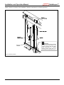
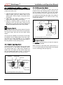
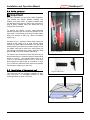
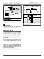
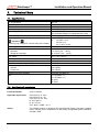
1
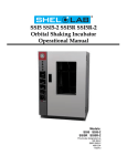
1-800-929-9247 USA and Canada Installation and Operation Manual © 2013 ADAMS Elevator Light Curtain for Elevator Door Protection GateKeeper™ www.adamselevator.com Part No. 102 994 / 130303A GateKeeper™ Installation and Operation Manual IMPORTANT NOTES FOLLOW THE INSTRUCTIONS GIVEN IN THIS MANUAL CAREFULLY. FAILURE TO DO SO MAY CAUSE CUSTOMER COMPLAINTS OR SERIOUS CALL BACKS. KEEP INSTRUCTION MANUAL ON SITE. WHEN THE GATEKEEPER™ LIGHT CURTAIN IS USED AS A REPLACEMENT FOR MECHANICAL SAFETY EDGES, IT IS THE RESPONSIBILITY OF THE INSTALLER TO ENSURE THAT ON COMPLETION, THE INSTALLATION COMPLIES WITH ALL THE RELEVANT FEDERAL, STATE AND LOCAL CODES AND REGULATIONS THAT APPLY TO YOUR APPLICATION. PARTICULAR ATTENTION SHOULD BE GIVEN TO CLAUSE 2.13.5 REOPENING DEVICES FOR POWER-OPERATED CAR DOORS OR GATES OUTLINED IN ASME A17.1-2007 / CSA B44-07 SAFETY CODE FOR ELEVATORS AND ESCALATORS. GATEKEEPER™ SYSTEMS MUST BE INSTALLED ONLY BY AUTHORIZED AND FULLY TRAINED PERSONNEL. PLEASE TAKE NOTE THAT OBJECTS THINNER THAN THE BEAM SPACING MAY NOT BE DETECTED. DO NOT USE THIS PRODUCT FOR THE PROTECTION OF DANGEROUS MACHINERY OR IN EXPLOSIVE ATMOSPHERES OR RADIOACTIVE ENVIRONMENTS. USE ONLY SPECIFIC AND APPROVED TYPES OF SAFETY DEVICES FOR SUCH APPLICATIONS. OTHERWISE SERIOUS INJURY OR DEATH MAY OCCUR. WHEN SUPPLY VOLTAGES GREATER THAN 42 VOLTS ARE USED, THE INTERFACE WIRING TO THE POWER SUPPLY AND TO THE DOOR DRIVE MUST BE MADE THROUGH A GREENFIELD FITTING. 2 www.adamselevator.com 1-800-929-9247 Installation and Operation Manual Content 1. Operation ...................................... 3 2. Applications................................... 3 3. Fail Safe Operation ........................ 4 4. Power Requirem ents ....................... 4 5. Installation .................................... 4 5.1. Installation of emitter / receiver .................... 6 5.1.1. Center opening doors ........................... 6 5.1.2. Side opening doors............................... 6 5.2. Cable guidance .......................................... 7 5.3. Installation of the control unit....................... 7 5.4. Electrical installation .................................... 8 5.4.1. Power supply ........................................ 8 5.4.2. Emitter ................................................. 8 5.4.3. Receiver ............................................... 8 5.4.4. Timer ................................................... 8 5.5. Relay Wiring ............................................... 9 5.6. Power-up and test ....................................... 9 5.7. Snap on the vison shield ............................ 10 5.8. Finished.................................................... 10 5.9. Maintenance............................................. 10 5.10. Disposal .................................................. 10 6. Troubleshooting ........................... 11 7. Technical Data ............................. 12 7.1. Specifications ............................................ 12 7.2. Certificate of compliance ........................... 12 7.3. Dimensions............................................... 13 7.3.1. Emitter / Receiver................................ 13 7.3.2. Control unit with housing .................... 14 8. GateKeeper™ Order Inform ation ... 15 8.1. Complete GateKeeper™ systems ................ 15 8.2. Spare parts ............................................... 15 8.3. Bill of materials ......................................... 15 9. W arranty ..................................... 16 1. Operation The infrared light curtain GateKeeper™ consists of three active parts: a control unit (A), an emitter unit with white connector (B), a receiver unit with blue connector (C), mounting components (D), and cables (E). GateKeeper™ The control unit is generally mounted on the car top or in the car operating panel and acts as an interface between any given supply voltage and the emitter / receiver. The control unit contains the operating system for the light curtain and controls the sensors in the emitter / receiver unit. To increase the life time of the electronic components, especially the infra red emitters, the control unit continuously controls the light emitting power according to the distance between the emitter and the receiver. When the doors are closed, the emitting power is almost zero. This function also prevents optical bypassing at the car door sill. B&C A E D Figure 1: System layout (refer to section 8.3 for a complete bill of materials) 2. Applications The mounting parts are configured so that they may be used for side opening doors as well as for center opening doors. The whole kit can be used for new installations as well as for modernization of existing elevators. The emitter unit and the receiver unit are generally mounted on the edge of the car door together with the mounting parts, opposite each other, covering the elevator entrance. 1-800-929-9247 www.adamselevator.com 3 GateKeeper™ Installation and Operation Manual Figure 2: Center opening door 3. Figure 3: Side opening door Fail Safe Operation 4. Power Requirements During normal operation, the GateKeeper™ light curtain system provides comfort for passengers by signaling the elevator control system to reopen the elevator cab doors. That said, infrared door protection systems, including the GateKeeper™ light curtain system, cannot provide absolute safety for elevator passengers passing through the elevator cab entryway as they are only a component of the overall elevator door protection system. The control unit contains state-of-the-art-technology to operate with any available supply voltage without any adjustments or special wiring. Any voltage from 17 Volts to 240 Volts AC or DC can be used and the light curtain will operate properly. If DC voltage is used the polarity to the terminals P and N is irrelevant. This feature is very useful, especially for modernization, where the supply voltage on the car top may not be precisely known. Elevator light curtains are not allowed to be used as the final failsafe device of the door mechanism. The ultimate safety function must be provided by a failsafe force and kinetic energy limiter. 5. Due to the nature of door system designs, there are extremely rare occurrences when the elevator doors can close even when an object or person is present. Therefore, federal, state and local codes require other safety means to prevent passengers from being hurt by the elevator doors during closure. These dangerous situations should be detected by the elevator control, which should take the elevator out of service. Final safety responsibility remains with the elevator integrator and/or contractor. 4 Installation Installation should be done in the following sequence: 1. Open the shipping box and verify that all components are present according to the bill of material (See Chapter 7) 2. Use proper barricading and displays to prevent public entry into the work area 3. Ensure that the elevator is taken out of service to prevent movement during installation (e.g. lockout / tagout procedure). 4. Install the emitter / receiver with the mounting or spacer profile to the door wings or to the slam post 5. Guide the cables of the emitter / receiver to the control unit using the cable ties and install the cable guide to prevent possible cable swing 6. Install the control unit 7. Perform electrical installation of the controller 8. Power-up and test 9. Snap on the vision shields to cover the emitter / receiver and install the cover to the control unit. www.adamselevator.com 1-800-929-9247 Installation and Operation Manual GateKeeper™ Figure 4 shows an overview of the installation. Details are provided in the following sections. Important The recommended distance between the door sill and the bottom of the sensors (mounting profile and spacer profile respectively) is ¼". A greater distance reduces safety due to an unprotected area right above the sill. Figure 4: Mounting overview 1-800-929-9247 www.adamselevator.com 5 GateKeeper™ Installation and Operation Manual 5.1. Installation of em itter / receiver 5.1.2. Side opening doors Use the following installation procedure to install the emitter and receiver units: The unit which is mounted to the slam post must be turned 90° from the mounting profile so that the sensors are looking "face-to-face". Use the sink screws that are provided to mount the edges to the slam post. It is important that the alignment angle of the emitter to the receiver is less than ± 10° when the door is fully closed (see Figure 6). #10 x ½" self drilling Spacerprofile profile Spacer Strike jamb <10° <10° Mounting profile We recommend installation of the sensors as far away as possible from the leading edge of the door to prevent them from being damaged, e.g. by vandalism (refer to Figure 4: Mounting overview and Figure 5: Mounting details of center opening doors). Figure 6: Mounting details of side opening doors Important We strongly recommend that you keep this angle as close to zero as possible. 5.1.1. Center opening doors The spacer profiles are mounted to the car door wings with six (6) #10 x ½" self drilling / self tapping screws. The spacer profile has a label which indicates the bottom side. The emitter and the receiver edge must then be installed using three (3) #6 x 1" sink screws through the pre-drilled holes on the spacer profiles. #10 x ½" self drilling min. 0.1 - 0.2" gap Important It is important that the active sensor sides of the emitter and receiver units are "face-to-face" to one another. The active sensor side has the round black plastic lenses. 0.925" (23.5) Car door 1.4" (35) 1. Install the spacer profile to the door with six (6) selftapping screws (note the 'bottom' label on the spacer profile. Refer to Figure 4 for proper mounting position. 2. Install either the emitter or receiver unit to the spacer profile using three (3) sink screws. 3. Install the remaining emitter or receiver unit (depending on which unit was used in step 2) on the strike jamb or on other door so that the alignment is as true as possible when the door is fully closed. When mounting to the strike jamb, ensure there is a 0.1" to 0.2" gap to allow the vision shield to be snapped on to the mounting profile (see Figure 6). Spacer profile Optical axis Left car door wing 1.1" (28) 0.5-3.0" (14-75) 0.95" (24) 1.4" (35) Right car door wing Light curtain Vision shield Figure 5: Mounting details of center opening doors 6 www.adamselevator.com 1-800-929-9247 Installation and Operation Manual GateKeeper™ 5.2. Cable guidance Important A It is very important to have proper cable installation. This ensures the highest possible reliability and lifespan of the light curtain. A properly installed cable can withstand more than 20 million door movements, while a poorly installed cable may break after only 100,000 door movements. To prevent the effects of stray electro-magnetic interference (EMI) that can affect the operation of the light curtain, it is important to route light curtain cables away from sources of EMI (e.g. motors, fluorescent lighting, etc.). B As shown in Fig. 7, guide the cables of the emitter and receiver to the control unit. A small bending radius reduces the cable lifetime dramatically. Use the cable binder A (see Figure 8) to fix the cable in place. Do not use plastic cable ties to secure the cable directly as this reduces the lifetime of the cable. Install the cable guide wire B to minimize potential cable swing. B Figure 7: Cable Guide The cables have connectors at both ends and may be disconnected from the controller and the corresponding emitter or receiver. The standard cable length of is 16 ft (5 m). An extension cable of 10 ft (3 m) is available to extend the total length to a maximum of 26 ft (8 m). Extension cables are often used for tall elevator cars with door heights up to 10 ft (3 m). 5.3. Installation of the control unit The control unit can be mounted horizontally or vertically using #10 x ½" self-tapping screws. An ideal mounting position is shown in Figure 4. Figure 8: Cable binder A Figure 9: GateKeeper Control unit 1-800-929-9247 www.adamselevator.com 7 GateKeeper™ Installation and Operation Manual When the supply voltage or the voltage at the relay terminal is below 42 volts, use the standard cable entrance gaskets to connect the emitter, the receiver, the relay and power. Connect all wiring with more than 42 V through a Greenfield Fitting. Disconnect power before opening the control unit to prevent electrical shock. Do not remove the fuse cap. NOTICE: The GateKeeper™ controller board is a printed circuit board that is sensitive to electrostatic discharge (ESD) and must be handled with care to prevent callbacks caused by improper handling. Utilize antistatic procedures when handling or making connection to the controller. Figure 11: Final installation with Greenfield Fitting (from T&B or other UL / CSA approved manufacturer) Figure 10: Knockout hole for Greenfield Fitting 5.4. Electrical installation 5.4.4. Tim er 5.4.1. Power supply N P The potentiometer near the blue receiver plug is used to set a door open hold time between 0 and 10 seconds. This function is useful e.g. in hospitals, where the doors should not close immediately after removing objects from the door zone. The factory setting is zero. : AC neutral, plus or minus for DC : AC Hot, plus or minus for DC : Protective ground 5.4.2. Em itter The white emitter connector must be plugged into the white marked plug. 5.4.3. Receiver The blue receiver connector must be plugged into the blue marked plug. 8 www.adamselevator.com 1-800-929-9247 Installation and Operation Manual GateKeeper™ Status Function Person or object detected Normal operation No Object Normal operation Problem Problem Problem refer to chapter 6 refer to chapter 6 Figure 12: Wiring diagram 5.5. Relay W iring The relay is energized when there is not an obstruction. It is de-energized during a beam obstruction, a fail safe condition or with no power applied. refer to chapter 6 Caption: : LED off : LED on : LED flashing Figure 13: Normal operation Important The contact rating is 250 VAC / 8 A, 125 VDC / 0.5 A, 30 VDC / 8 A, min. 5 VDC / 10 mA. Use a pilot relay if switching 125 VDC loads which exceed 0.5 A. 5.6. Power-up and test Ensure that all job site wiring and connections are correct and then apply power. The buzzer produces an intermittent beeping for approximately 2-3 seconds. After this start-up beeping the relay is energized so that the doors can close. However, when there is any obstacle in the protected area, the relay will remain deenergized until the whole area is free and all beams are established. With the obstruction of one or more beams the light curtain output relay will deenergize and the 'OUT'-LED will illuminate to indicate an obstructed beam condition. Installation Tip: When the buzzer is switched on with the sliding switch (see Figure 13: Normal operation), a disrupted beam condition is also indicated with a buzzer signal. This function is very helpful after installation to check the proper function of the light curtain. If the light curtain does not operate as described in this section, please refer to Chapter 6 'Troubleshooting'. 1-800-929-9247 www.adamselevator.com 9 GateKeeper™ Installation and Operation Manual 5.7. Snap on the vison shield 5.8. Finished The vision shield is a high-tech plastic part which covers the emitter and receiver but allows infrared light to pass through with virtually no power loss. The vision shield is made from a polycarbonate (PC) material that is very tough and stable and is chemically resistant to many alcohols and cleaning solvents. Congratulations, you have successfully installed one of the most powerful, reliable and cost effective door protection systems available today. It will benefit your customers for many years to come. Installation Tips: The following procedure provides the simplest means of installing the vision shield on to a spacer profile or mounting profile. It is important to note that the vision shield cannot be easily adjusted after complete installation. Care should be taken to begin the installation carefully to ensure proper location of the vision shield on the spacer or mounting profile. There is no special maintenance required for the light curtain. We recommend checking the proper function of the light curtain installation during normal elevator service. Proper function of the light curtain is evident when • the doors reopen immediately after an obstruction of the protected area. • the sensors are fastened securely on the door and strike jamb. • the cables are routed properly as described in section '5.2 Cable Guidance'. 1. Start at the BOTTOM of the door. Align the end of the vision shield to the end of the mounting or spacer profile. 2. Snap in the FIRST FEW INCHES by spreading the side walls of the vision shield. 3. Snap in FROM BOTTOM TO TOP and bend the vision shield slightly backwards (see Figure 14). 4. After installation, we recommend cleaning the vision shield for a nice appearance using a soft, dry towel. 5.9. Maintenance Important Do not use any aggressive cleaning solvents like Acetone or Trichloride or mechanically abrasive towels to clean the vision shields, the receiver redge and the emitter edge. They may become "blind" and will not pass infra red light anymore. We strongly recommend using standard window cleaners or soap and water for cleaning. 5.10. Disposal The light curtain should only be replaced if a similar door protection device is installed. Disposal should be done through state of the art recycling technology according to local rules and laws. There are no harmful materials used in the design and manufacture of the light curtain. Traces of such dangerous materials could be used in the electronic components but not in quantities that are harmful to health. Figure 14: Snap on the vision shield 10 www.adamselevator.com 1-800-929-9247 Installation and Operation Manual 6. GateKeeper™ Troubleshooting If the light curtain does not operate as described in '5.6 Power-up and test', the following trouble shooting procedure should be used: Problem What to check? No function, door open (dead!) • • • • Door open, free protective area • • • • Random door openings Receiver problem Refer to Power supply good? Fuse broken? Power wire broken? Defect control unit? All beams not interrupted? Are the sensors looking "face-to-face"? Dirty sensors or vision shields? Bad alignment? Excessive EMC interference e.g. from door drive or fluorecent lamps? • No or bad grounding (PE) connection? 5.1.1 5.1.2 5.9 • Dirty sensors or vision shields? • Excessive EMC interference e.g. from door drive or fluorecent lamps? • No or bad grounding (PE) connection? • Damaged cable to the receiver or emitter, check for break in the cables by moving the cable by hand? • Interference with other infra red sensors with the receiver directly or via mirroring from shiny surfaces? 5.1.1 5.1.2 5.4.1 5.4.1 • Receiver not connected? • Emitter connected to the receiver plug instead of the emitter plug? • Cable to the receiver broken or defective receiver? • Extension cables too long? 5.2 Emitter problem • Emitter not connected? • Receiver connected to the emitter plug instead of the receiver plug? • Cable to the receiver broken or defective emitter? • Extension cables too long? 5.2 Receiver and emitter problem • Emitter and receiver not connected? 5.2 Caption: : LED off : LED on : LED flashing 1-800-929-9247 www.adamselevator.com 11 GateKeeper™ 7. Installation and Operation Manual Technical Data 7.1. Specifications No. of light beams Typical response time Max response time Operating range Power supply voltage Power consumption Relay output Important If switching high voltage DC, use pilot relay (not included) Ambient light Temperature range - Operation - Storage and transport Door speed Cable length of the sensor (detachable) Cable extension for the sensors (optional) Cable lifetime (if correctly installed) Enclosure rating - Sensors - Control unit Vibration and shock resistance EMC max. 154 90 ms 180 ms 0 to 16 ft (0 to 5 m) 17 … 240 VAC / DC (use "Greenfield Fittings" for voltage above 42 volts) max. 5 VA @ 115 / 230 VAC / 50 mA @ 24 VDC AC: 250 VAC / 8 A DC 125 VDC / 0.5 A 30 VDC / 8 A, min. 5 VDC / 10 mA > 100,000 Lux -5° to 150°F (-20 … +65°C) -20° to 220°F (-30 … +85°C) max. 5.3 ft/s (1.6 m/s) 16 ft (5 m) 10 ft (3 m) 20 million door movements Type 4 (IP65) Type 3 (IP54) IEC 68-2-6 / IEC 68-2-29 IEC / EN 50081-1,-2 IEC / EN 50082-1,-2 EN 12015 EN 12016 7.2. Certificate of com pliance Certificate Number: 187273-1394504 Applicable requirements CSA C22.2 No. 0 - M91 CSA C22.2 No.14 - 95 CSA C22.2 No. 94 - M91 UL 508, 16th ed. UL 50, 11th ed. CSA - B44.1 / ASME - A17.5 Quality This ADAMS product is developed and manufactured following generally accepted rules in industry and in compliance to a total quality management system certified to ISO 9001: 2008. 12 www.adamselevator.com 1-800-929-9247 Installation and Operation Manual GateKeeper™ 7.3. Dim ensions 7.3.1. Em itter / Receiver All dimensions in mm (Inches) Cross section of the sensors : 12 x 16 mm (0.47" x 0.63") Diameter of mounting holes : 4.5 mm (0.18") 1-800-929-9247 www.adamselevator.com 13 GateKeeper™ Installation and Operation Manual 7.3.2. Control unit with housing All dimensions in mm (Inches) 14 www.adamselevator.com 1-800-929-9247 Installation and Operation Manual 8. GateKeeper™ GateKeeper™ Ordering Information 8.1. Com plete GateKeeper™ system s ADAMS Part No. A850G7 1) A850G10 1) Description GateKeeper™ with 7 foot mounting kit for door heights up to 7 feet GateKeeper™ with 10 foot mounting kit for door heights greater than up to 10 feet Note: 1) For system bill of material, please refer to table 8.3 (below) 8.2. Spare parts ADAMS Part No. Description A850G7-P1 GateKeeper™ Control Unit A850G7-R1 GateKeeper™ Receiver A850G7-T1 GateKeeper™ Emitter A850G7-RR1 Receiver cable, 16 ft (5m) length A850G7-RT1 Emitter cable, 16 ft (5m) length A850G7-RR2 Receiver extension cable, 10 ft (3m) length A850G7-RT2 Emitter extension cable, 10 ft (3m) length A850G7-LGW Cable Guide Wire A850G7-SP Spacer Profile, 7 ft length A850G10-SP Spacer Profile , 10 ft length A850G7-MP Mounting Profile, 7 ft length A850G10-MP Mounting Profile , 10 ft length A850G7-VS Vision Shield, 7 ft length A850G10-VS Vision Shield, 10 ft length A850G7-INS Installation and Operation Manual A850G7-HW Hardware Bag 8.3. Bill of m aterials ADAMS Part No. Qty included in each system Description A850G7-P1 GateKeeper™ Control Unit 1 A850G7-R1 GateKeeper™ Receiver 1 A850G7-T1 GateKeeper™ Emitter 1 A850G7-RR1 Cable Receiver 16' 1 A850G7-RT1 Cable Emitter 16' 1 A850G7-LGW Cable Guide Wire 2 A850G7-SP Spacer Profile, 7 ft length 2 2) A850G10-SP Spacer Profile , 10 ft length 2 2) A850G7-MP Mounting Profile, 7 ft length 1 2) A850G10-MP Mounting Profile , 10 ft length 1 2) A850G7-VS Vision Shield, 7 ft length 2 2) A850G10-VS Vision Shield, 10 ft length 2 2) A850G7-INS Installation and Operation Manual 1 A850G7-HW Hardware Bag containing the necessary screws, cable binders and cable holders 1 Notes: 2) A850G7 includes spacer profiles, vision shields and a mounting profile with 7 foot lengths. A850G10 includes spacer profiles, vision shields and a mounting profile with 10 foot lengths. 1-800-929-9247 www.adamselevator.com 15 GateKeeper™ 9. Installation and Operation Manual Warranty Instructions for Returning GateKeeper™ Systems and Components 1. GateKeeper™ is warranted to be free from manufacturing and material defects for 5 years. To verify that your product qualifies for warranty replacement, check the product date code. The date code is defined by the first six numbers following “Lot” on the st product label. For example, 090901, represents the year, month and day of manufacture (2009, September, 1 ). 2. If you have already ordered a complete new system (controller, edges, shields, hardware, etc.), you must return a complete system in order for you to receive full credit. Use the component(s) from the new system that are necessary to make repairs. Then return the unused components as well as the components that were replaced in the same box (i.e. the components being returned can be a mix of new and used components). You will only receive a credit for a complete system when a complete system is returned. 3. Before shipping the returned components to , you must obtain a return authorization number (RA Number). Please con- customer service at the telephone number listed on the operating instructions for the device. You will also need to tact provide a sales order number in order to apply for credit. 4. A pre-paid return label has been included for your convenience. Make sure that the Return Authorization number (RA Number) is marked on the packaging to ensure that you receive proper credit for the return. Adams Elevator Equipment Company 6310 West Howard Niles, Illinois 60714-3406 USA Adams Elevator Equipment Company Canada 75 Horner Avenue, Unit 3 Toronto, Ontario M8Z 4X5 Canada Manufactured for Adams Elevator by CEDES. CEDES AG is certified according to ISO 9001:2008. CEDES AG reserves the right to modify / change technical data without notice.