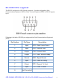
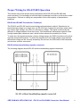
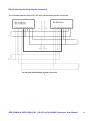
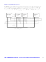
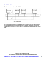
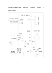
1
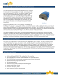
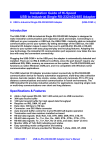
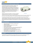
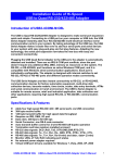
RS-232 to RS-422/485 Converters User Guide Models : SER-COMi-M SER-COMi-SI-M Web: www.titan.tw Support: [email protected] Document Part Number TN-068 Version 1.00 Issue Date: 2011-09-11 The computer programs provided with the hardware are supplied under a license. The software provided should be used only with the IP-COM series hardware designed and manufactured by TITAN Electronics Inc. Trademarks TITAN and the logo is a registered trademark of TITAN Electronics Inc. in Taiwan. Microsoft, Windows, Windows XP, Windows Vista, Windows Server, Windows 7, Windows 8 are trademarks of Microsoft Corporation. All other trademarks and brands are property of their respective owners. Copyright Copyright 2011-2015 TITAN Electronics Inc. All right reserved. Reproduction of the manual and software without permission is prohibited. Disclaimer TITAN Electronics Inc. provides this document and computer programs “as is” without warranty of any kind, either expressed or implied, including, but not limited to, its particular purpose. TITAN Electronics Inc. reserves the right to make improvements and changes to this user manual, or to the products, or the computer programs described in this manual, at any time. Information provided in this manual is intended to be accurate and reliable. However, TITAN Electronics Inc. assumes no responsibility for its use, or for any infringements on the rights of third parties that may result from its use. This product might include unintentional technical or typographical errors. Changes are periodically made to the information herein to correct such errors, and these changes are incorporated into new editions of the publication. SER-COMi-M & SER-COMi-SI-M RS-232 to RS-422/485 Converters User Manual 1 Content Introduction & Specifications of Hi-Speed RS-232 to RS-422/485 Converters.................................................................................................... 3 Introduction of SER-COMi-M & SER-COMi-SI-M ........................................ 3 Features of Optical Isolation & Surge Protection (SER-COMi-SI-M) ........ 3 Specifications & Features ........................................................................... 4 RS-232 to RS-422/485 Converter (SER-COMi-M)........................................................ 4 Opto-isolated RS-232 to RS-422/485 Converter (SER-COMi-SI-M) ............................. 4 Power Supply ............................................................................................... 5 Setting of RS-232 to DCE or DTE................................................................ 5 RS-232 DCE Pin Assignment ...................................................................... 6 RS-232 DTE Pin Assignment ...................................................................... 7 RS-422 Output Port Pin Assignment of DB9 Male Connector .................. 8 RS-422 Mode Pin-out ................................................................................................... 8 RS-485 Output Port Pin Assignment of DB9 Male Connector .................. 9 RS-485 Full Duplex Mode Pin-out ................................................................................ 9 RS-485 Half Duplex Mode Pin-out .............................................................................. 10 RS-422 Output Port Pin Assignment of 5-pin Terminal Block ................ 11 RS-422 Mode Pin-out ................................................................................................. 11 RS-485 Output Port Pin Assignment of 5-pin Terminal Block ................ 12 RS-485 Full Duplex Mode Pin-out .............................................................................. 12 RS-485 Half Duplex Mode Pin-out .............................................................................. 13 RS-422 & RS-485 Mode Configuration ..................................................... 14 Termination and Biasing Option Configuration ...................................... 15 Termination Resistor................................................................................................... 15 Biasing Resistors ........................................................................................................ 15 Jumper Setting to Enable Termination & Biasing Resistors ........................................ 16 Proper Wiring for RS-422/485 Operation.................................................. 17 RS-422 and RS-485 Transmission Technique ........................................................... 17 RS-422 without handshaking signals connected ........................................................ 17 RS-422 with handshaking signals connected ............................................................. 18 RS-422 and RS-485 4-Wire Scheme .......................................................................... 19 RS-485 2-Wire Scheme .............................................................................................. 20 SER-COMi-M & SER-COMi-SI-M RS-232 to RS-422/485 Converters User Manual 2 Introduction & Specifications of Hi-Speed RS-232 to RS-422/485 Converters RS-232 to RS-422/485 Converter (SER-COMi-M) Opto-isolated RS-232 to RS-422/485 Converter (SER-COMi-SI-M) - with optical isolation (2000V) - with surge protection (25KV ESD) on all signal lines to prevent interference, to protect system and minimize down time Introduction of SER-COMi-M & SER-COMi-SI-M The SER-COMi-M and SER-COMi-SI-M are used to convert RS-232 signals to RS-422/485 signals. The converters provide instant connectivity to RS-422/485 communication devices for factory automation equipment, multi-drop data collection devices, barcode readers, time clocks, scales, data entry terminals, PC to PC long distance communications (up to 1.3KM) and serial communication in harsh environments. The SER-COMi-M and SER-COMi-SI-M provide an industrial solution for applications requiring single node or multi-drop communications over short and long distance. In RS-485 half-duplex mode, the SER-COMi-M and SER-COMi-SI-M also provide automatic data transmit/receive control. Features of Optical Isolation & Surge Protection (SER-COMi-SI-M) Optical isolation and surge protection are available to SER-COMi-SI-M. The SER-COMi-SI-M converter is optically isolated with 2000 Volt DC optical isolation. The optical isolation protects your PC from spikes and surges on the RS-422/485 network, by converting the electrical pulse into an optical signal and then changing it back into an electrical pulse. Your computer is well protected, since the surges and spikes cannot cross the optical link. The SER-COMi-SI-M is protected by surge protector to withstand electrostatic discharge and power surges up to 25KV ESD. Surge suppression on all signals prevent from damages caused by lightning or high voltage. SER-COMi-M & SER-COMi-SI-M RS-232 to RS-422/485 Converters User Manual 3 Specifications & Features RS-232 to RS-422/485 Converter (SER-COMi-M) Converts RS-232 port to high speed RS-422 / 485 port RS-232 port can be selected to DCE or DTE pin assignment Data rates: 300 bps to 1M bps RS-232 Connector: One DB-9 female connector RS-422/485 Connector: One DB-9 male connector and one 5-pin terminal blocks Auto transmit/receive control for 2-wire RS-485 half-duplex operation Termination and Bias resistors installed on-board RS-422 data signals: TX-, TX+, RX+, RX-, GND, RTS-, RTS+, CTS+, CTSRS-485 data signals: TX-, TX+, RX+, RX- (4 wire), and data-, data+ (2 wire) Monitor LEDs of TxD, RxD indicating port status Wide input power range: 9V DC to 48V DC Includes an external switching terminal power adapter Opto-isolated RS-232 to RS-422/485 Converter (SER-COMi-SI-M) Converts RS-232 port to high speed RS-422 / 485 port RS-232 port can be selected to DCE or DTE pin assignment RS-422/485 port is optically isolated with 2000 Volt DC optical isolation RS-422/485 port is protected by surge protector on all signal lines to withstand electrostatic discharge and power surges up to 25KV ESD Data rates: 300 bps to 1M bps RS-232 Connector: One DB-9 female connector RS-422/485 Connector: One DB-9 male connector and one 5-pin terminal blocks Auto transmit/receive control for 2-wire RS-485 half-duplex operation Termination and Bias resistors installed on-board RS-422 data signals: TX-, TX+, RX+, RX-, GND, RTS-, RTS+, CTS+, CTSRS-485 data signals: TX-, TX+, RX+, RX- (4 wire), and data-, data+ (2 wire) Monitor LEDs of TxD, RxD indicating port status Wide input power range: 9V DC to 48V DC Includes an external switching terminal power adapter SER-COMi-M & SER-COMi-SI-M RS-232 to RS-422/485 Converters User Manual 4 Power Supply The SER-COMi-M and SER-COMi-SI-M are working in wide input power range from 9V DC to 48V DC. An external switching terminal power adapter is provided in the package. 9V DC to 48V DC power input connector Setting of RS-232 to DCE or DTE Inside the converter, there are two 2x3 (JP1, JP2) header blocks which are jumpered to select the RS-232 port pin assignment to DCE or DTE. Jumper JP1 1-3 2-4 JP2 1-3 2-4 JP1 3-5 4-6 JP2 3-5 4-6 Function RS-232 port assigned to DCE (Data Communications Equipment). (See Figure 2) RS-232 port assigned to DTE (Data Terminal Equipment). (See Figure 3) The factory default setting is DCE Fig 2. DCE setting SER-COMi-M & SER-COMi-SI-M Fig 3. DTE setting RS-232 to RS-422/485 Converters User Manual 5 RS-232 DCE Pin Assignment The RS-232 serial port is a DB-9 female connector. It can be configured as Data Communications Equipment (DCE) or Data Terminal Equipment (DTE) for RS-232 signals input. Following is the table of RS-232 pin assignments for Data Communications Equipment (DCE). Pin Number Pin Type 1 Input DCD : Data Carrier Detect 2 Input RXD : Receive Data 3 Output TXD : Transmit Data 4 Output DTR : Data Terminal Ready 5 Ground GND : Signal Ground 6 Input DSR : Data Set Ready 7 Output 8 Input 9 Not Connected SER-COMi-M & SER-COMi-SI-M Description RTS : Request To Send CTS : Clear To Send RS-232 to RS-422/485 Converters User Manual 6 RS-232 DTE Pin Assignment The RS-232 serial port is a DB-9 female connector. It can be configured as Data Communications Equipment (DCE) or Data Terminal Equipment (DTE) for RS-232 signals input. Following is the table of RS-232 pin assignments for Data Terminal Equipment (DTE). Pin Number Pin Type 1 Input 2 Output TXD : Transmit Data 3 Input RXD : Receive Data 4 Input DSR : Data Set Ready 5 Ground GND : Signal Ground 6 Output DTR : Data Terminal Ready 7 Input 8 Output 9 Not Connected SER-COMi-M & SER-COMi-SI-M Description DCD : Data Carrier Detect CTS : Clear To Send RTS : Request To Send RS-232 to RS-422/485 Converters User Manual 7 RS-422 Output Port Pin Assignment of DB9 Male Connector RS-422 Mode Pin-out The table below shows the SER-COMi-M/ SER-COMi-SI-M’s RS-422 mode pin-out of the DB-9 male connector. Pin Number Pin Type 1 Output TxD- : Transmit Data , negative polarity 2 Output TxD+ : Transmit Data , positive polarity 3 Input RxD+ : Receive Data , positive polarity 4 Input RxD- : Receive Data , negative polarity 5 Ground GND : Signal Ground 6 Output RTS- : Request To Send, negative polarity 7 Output RTS+ : Request To Send, positive polarity 8 Input CTS+ : Clear To Send, positive polarity 9 Input CTS- : Clear To Send, negative polarity SER-COMi-M & SER-COMi-SI-M Description RS-232 to RS-422/485 Converters User Manual 8 RS-485 Output Port Pin Assignment of DB9 Male Connector RS-485 Full Duplex Mode Pin-out The table below shows the SER-COMi-M/ SER-COMi-SI-M’s RS-485 full-duplex mode pin-out of the DB-9 Male connector. Pin Number Pin Type 1 Output TxD- : Transmit Data , negative polarity 2 Output TxD+ : Transmit Data , positive polarity 3 Input RxD+ : Receive Data , positive polarity 4 Input RxD- : Receive Data , negative polarity 5 Ground SER-COMi-M & SER-COMi-SI-M Description GND : Signal Ground RS-232 to RS-422/485 Converters User Manual 9 RS-485 Half Duplex Mode Pin-out The table below shows the SER-COMi-M/ SER-COMi-SI-M’s RS-485 half duplex mode pin-out of the DB-9 male connector. Pin Number Pin Type Description 1 Out/In Data- : Transmit /Receive Data , negative polarity 2 Out/In Data+ : Transmit /Receive Data , positive polarity 5 Ground GND : Signal Ground SER-COMi-M & SER-COMi-SI-M RS-232 to RS-422/485 Converters User Manual 10 RS-422 Output Port Pin Assignment of 5-pin Terminal Block RS-422 Mode Pin-out The table below shows the SER-COMi-M/ SER-COMi-SI-M’s RS-422 mode pin-out of the 5-pin terminal bock connector. Pin Number Pin Type 1 Output TxD- : Transmit Data , negative polarity 2 Output TxD+ : Transmit Data , positive polarity 3 Input RxD+ : Receive Data , positive polarity 4 Input RxD- : Receive Data , negative polarity 5 Ground SER-COMi-M & SER-COMi-SI-M Description GND : Signal Ground RS-232 to RS-422/485 Converters User Manual 11 RS-485 Output Port Pin Assignment of 5-pin Terminal Block RS-485 Full Duplex Mode Pin-out The table below shows the SER-COMi-M/ SER-COMi-SI-M’s RS-485 full-duplex mode pin-out of the 5-pin terminal bock connector. Pin Number Pin Type 1 Output TxD- : Transmit Data , negative polarity 2 Output TxD+ : Transmit Data , positive polarity 3 Input RxD+ : Receive Data , positive polarity 4 Input RxD- : Receive Data , negative polarity 5 Ground SER-COMi-M & SER-COMi-SI-M Description GND : Signal Ground RS-232 to RS-422/485 Converters User Manual 12 RS-485 Half Duplex Mode Pin-out The table below shows the SER-COMi-M/ SER-COMi-SI-M’s RS-485 half duplex mode pin-out of the 5-pin terminal block connector. Pin Number Pin Type Description 1 Out/In Data- : Transmit /Receive Data , negative polarity 2 Out/In Data+ : Transmit /Receive Data , positive polarity 5 Ground GND : Signal Ground SER-COMi-M & SER-COMi-SI-M RS-232 to RS-422/485 Converters User Manual 13 RS-422 & RS-485 Mode Configuration Outside the converter, there is a 3-pin DIP switches which are set to select the mode of operation. You will need to set the switch settings to RS-422 mode, or RS-485 mode, as per the requirements of your application. The RS-422 & RS-485 Mode Block Configuration Settings are listed as follows. RS-422 Operation Mode 4 wire with handshaking RS-485 Full Duplex (4 wire) S1 S2 S3 ON ON ON ON ON OFF Half Duplex (2 wire) with Echo OFF OFF Half Duplex (2 wire ) without Echo OFF OFF SER-COMi-M & SER-COMi-SI-M ON OFF RS-232 to RS-422/485 Converters User Manual 14 Termination and Biasing Option Configuration Termination Resistor When transmitted signals arrive at the end of a cable, they get reflected. They travel on the cable some more times, which is called ringing. This can cause false reading of transmitted data. For long cables termination resistors are required. These increase the damping of reflection. The value of the termination resistor must match the impedance of the cable, typically 120 ohms. Biasing Resistors In RS-485 operation, the sender must activate the transmitter before sending data, and deactivate it when all data is sent. At times when no devices send data all transmitters are inactive. As the result the data lines are floating, and the differential voltage is undefined. It may happen the next data is not correctly recognized, because the change from undefined to data signals is not detected. To avoid such problems the data lines should be polarized by biasing resistors. The biasing resistors must not be too small, typical biasing resistors are 750 ohms in high and low level. SER-COMi-M & SER-COMi-SI-M RS-232 to RS-422/485 Converters User Manual 15 Jumper Setting to Enable Termination & Biasing Resistors Inside the converter, there is one 7 x 3 (21 pins, Fig. 4) header blocks which are jumpered to enable Tx, Rx, CTS 120 Ohm termination resistors and Rx, Tx 750 Ohm biasing resistor. You will need to open up the metal case and set the jumpers to RS-422 mode or RS-485 mode as per the requirements of your application. Termination and biasing settings are listed as follows: 3 2 1 21 20 19 Fig. 4 Termination and Biasing resistors setting Jumper 1-2 enable 2-3 disable 4-5 enable 5-6 disable 7-8 enable 8-9 disable 10-11 enable 11-12 disable 13-14 enable 14-15 disable 16-17 enable 17-18 disable 19-20 enable 20-21 disable Function Tx+/- Termination of 120 Ohm. This jumper should always be populated for RS485 Half-Duplex mode. Pull-up Tx+ to VCC by 750 Ohm Bias resistor. This jumper should be populated for pull-up Tx+. Pull-down Tx- to GND by 750 Ohm Bias resistor. This jumper should be populated for pull-down Tx-. Rx+/- Termination of 120 Ohm. This jumper should always be populated for RS-422 and RS-485 Full-Duplex mode. Pull-up Rx+ to VCC by 750 Ohm Bias resistor. This jumper should be populated for pull-up Rx+. Pull-down Rx- to GND by 750 Ohm Bias resistor. This jumper should be populated for pull-down Rx-. CTS Termination of 120 Ohm. This jumper should always be populated for RS-422 mode. Note: Sometimes, when operating in RS-422 or RS-485, it is necessary to configure termination and biasing of the data transmission lines. Generally this must be done in the cabling, since this depends on the installation of connections. Before applying the option, check your cable specification for proper impedance matching. Biasing of data lines must only occur at a single point anywhere in the cabling. SER-COMi-M and SER-COMi-SI-M provide biasing for ease of installation. Please be sure to disable this inside the unit, if your cabling already provides biasing. Termination must not be installed in the middle of the cable. It is only permitted at both ends. Since a computer controlled serial port is almost always at one end of the cable, termination is enabled by default. SER-COMi-M & SER-COMi-SI-M RS-232 to RS-422/485 Converters User Manual 16 Proper Wiring for RS-422/485 Operation This section will provide proper wiring information about RS-422 and RS-485 data communication. It is necessary to have the basic knowledge to avoid or to find errors in data transmission. Failures in cabling are responsible for the vast majority of transmission problems. RS-422 and RS-485 Transmission Technique The RS-422 and RS-485 use the same balanced transmission method. Signals are not transmitted as voltage on a single wire, as RS-232 does. Instead two wires are used; when one carries high voltage, the other one carries low voltage. The signal is defined by the different in voltage between those two wires. This hardens the transmission against noise. Usually twisted pair cables are used, which further reduces the sensitivity for noise. To make sure the signals meet the common voltage range, the GND of sender and receiver must be connected somehow. To insure the signals are in the valid voltage range and the differential voltage can be correctly sensed by the receiver the GND lines of the transmitter and receiver must be connected. RS-422 without handshaking signals connected The following diagram shows RS-422 without handshaking signals connected. SER-COMi-M & SER-COMi-SI-M RS-232 to RS-422/485 Converters User Manual 17 RS-422 with handshaking signals connected The following diagram shows RS-422 with handshaking signals connected. SER-COMi-M & SER-COMi-SI-M RS-232 to RS-422/485 Converters User Manual 18 RS-422 and RS-485 4-Wire Scheme The RS-422 requires dedicated wire pairs for transmit and receive. The transmit wires are used to send data to as many as 10 receivers, as stated in the specifications of RS-422. Since the SER-COMi-M/SER-COMi-SI-M uses RS-485 line driver technology, up to 32 receivers are possible. The following diagram shows RS-422 and RS-485 4-wire scheme: SER-COMi-M & SER-COMi-SI-M RS-232 to RS-422/485 Converters User Manual 19 RS-485 2-Wire Scheme The following diagram shows RS-485 2-Wire scheme: The RS-485 operation of SER-COMi-M/SER-COMi-SI-M allows for 2-wire cabling, Several RS-485 2-wire devices are connected in parallel to the wires, which is call bus topology. Each device can either send or receive data at a given time, so it is operating in half-duplex mode. Copyright © 2011 TITAN Electronics Inc All brand names and trademarks are the property of their respective owners. SER-COMi-M & SER-COMi-SI-M RS-232 to RS-422/485 Converters User Manual 20