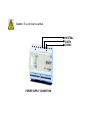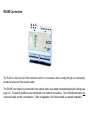
1
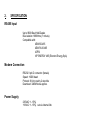
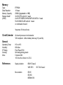
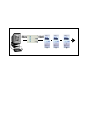
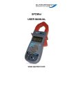
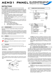
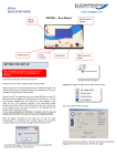
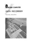
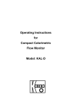
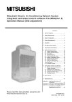
ELCOMPONENT L TD LTD R-DCU - R emote Da Remote Dat ta Collection Unit User Manu al Manual CONTENTS Page 1. GENERAL ............................................................................................. 1 2. SPECIFICATION .................................................................................... 4 3. INSTALLATION AND INSTRUCTIONS .................................................. 6 4. INSTRUMENT SET-UP AND RESET ...................................................... 11 All rights reserved. No part of this publication may be reproduced, stored in a retrieval system, or transmitted in any form or by any means, electronic, mechanical, photocopying, recording or otherwise, without the prior written permission of Elcomponent Ltd. While every precaution has been taken in the preparation of this manual, Elcomponent Ltd assumes no responsibility for errors or omissions. Neither is any liability assumed for damages resulting from the use of the information contained herein. Elcomponent Ltd shall not be liable to the purchaser of this product or third parties for damages, losses, costs, or expenses incurred by purchaser of modifications, repairs, or alterations to this product, or failure to strictly comply with the published operating and maintenance instructions. 1 GENERAL About this manual This manual provides the information required to install and operate the R-DCU. For further information please refer to your supplier or to the manufacturers: Elcomponent Ltd Unit 5 Southmill Trading Centre Southmill Road Bishops Stortford Herts CM23 3DY Tel: 01279 503173 Fax: e-mail: [email protected] web site: www.elcomponent.co.uk 01279 654441 About the R-DCU The Elcomponent R-DCU is a high quality data collection and communication device for use with Elcomponents MeterRingTM2000 software package. The R-DCU is a microprocessor based electronic unit utilising a solid state memory. All settings and readings apart from the realtime clock are retained without the use of a back-up battery. The clock back-up is via a lithium cell with a life of approximately 10 years, making the unit essentially maintenance free. The R-DCU is designed to provide a hub for meter networks situated remotely from the host PC. It provides all the necessary network management functions for the devices connected to it via the RS485 bus, along with secure data retention. It also provides a modem interface facility for standard modems enabling automatic communication to the PC operating as the ultimate network host. SYMBOLS: The following symbols are used in this manual and on the instrument itself. CAUTION: Failure to follow the instructions may result in personal injury or damage to equipment. . NOTE: Failure to follow the instructions may result in an instrument malfunction. Safety Precautions The R-DCU is designed for use on supply voltages of 240VAC or 110VAC nominal. To ensure safe operation the unit must be connected to the correct supply voltage. The instructions contained in this manual and the safety markings on the product must be complied with. Before connecting the unit ensure the supply voltage is within the range specified for the product. Operation of the instrument with the case removed or damaged may expose live parts and could be dangerous. Before carrying out service or repair the unit must be disconnected from all voltage and current sources. The capacitors inside the unit may be charged even if the instrument is disconnected. The instrument must be connected via a fuse, of the rating and type specified. 2. SPECIFICATION RS485 Input Up to 9600 Baud Half-Duplex Bus isolation 1680Vrms (1 minute) Compatible with: AEM31D-485 AEM PLUS 485 4CPSI VIP ENERGY 485 (Elcontrol Energy SpA) Modem Connection RS232 9 pin D connector (female) Speed: 19200 baud Protocol: 8 bit no parity 2 stop bits Download: 32kB/minute approx. Power Supply 230VAC +/- 15%) 110VAC +/- 15%) set via internal link Memory Type: Data Retention: Memory Capacity: Storage Detail:* (256K) E2PROM 10 Years 256kB (Upgradable to 1MB) 32 off 4CPSI units for 1 week 24 off VIP ENERGY 485/AEM PLUS 485 for 1 week 50 off AEM31D-485 units for 1 week or combination thereof. *Assumes 30 min poll rate. Clock/Calendar General On-board processor clock/calendar Y2K compliant. Lithium battery back-up (10 year life) Operating Temp: Humidity: IP Rating: Housing: Dims: 0oC to 40oC 80% Max Front Panel IP40 Self extinguishing plastic 9 module DIN 157.5mm W x 90mm H x 73 D References Supply isolation: BS415 Class 2 VDE 0551 IEC 742 Class 2 Bus isolation: IEC65 IEC950 BSEN41003 3. INSTALLATION INSTRUCTIONS Inspection: On receipt of the instrument ensure that it is complete and undamaged. It consists of: 1 off instrument R-DCU 1 off modem connection cable 1 off pc connection cable 1 off Instruction Manual Mounting: The unit is of the DIN rail mounting type and conforms to DIN 43370 dimensions (9 modules). 35mm top hat profile DIN rail should be utilised for attachment of the unit to a suitable surface. Electrical Connections: Power Supply: CAUTION: The unit is suitable for connection to a 240/110VAC supply. Ensure that the correct supply is available before connecting, and is the same as the voltage marked on the product CAUTION: The unit is fitted with an internal fuse. However it is recommended that an external fuse is fitted to the power supply. Fuse Type: 2A, 250VAC Type T. HBC Caution: The unit must be earthed NEUTRAL EARTH 230VAC POWER SUPPLY CONNECTION MODEM/PC CONNECTION: If the unit is to communicate via telephone line, an external modem is required. (See Appendix B for recommended modems). The R-DCU has been extensively tested with the modems listed, but may work satisfactorily with good quality alternative devices. . . NOTE: It is essential that the unit is connected using the cable supplied. Use of a different cable will not work. NOTE: It is strongly recommended that the R-DCU is used with the modem connected to a dedicated telephone line. Similarly if the R-DCU is to communicate directly to a PC, a connection must be made to the serial port of the PC using the cable provided. RS485 Connection B A S The R-DCU is the host unit of the network to which it is connected, and is usually (though not necessarily) situated at one end of the network cable. The RS485 input should be connected to the network cable via suitable screened twisted pair cabling (see page 14). The polarity (A&B) must be maintained on all network connections. The S (Shield) terminal is not connected under normal circumstances. Refer to Appendix A for further details on network installation. 4. SET UP AND OPERATION When the unit is connected to the power supply as detailed above it will power up and the green power led will illuminate The unit requires no external setting up. Once it is in operation the led status will be as follows: i) ii) iii) iv) Green Power led: On. Flashes off every 5 seconds to indicate correct operation of the microprocessor. Red Busy led: Off. Flashes on to indicate the unit is processing data. Yellow Poll led: Off. Flashes on to indicate the unit is polling the local network (usually on the hour and half hour). Amber RX Ready led: On. Flashes off when contacted via modem or PC on the RS232 port. NOTE: The power up sequence of the R-DCU and modem is important. Always switch the modem on first, then power up the R-DCU. This is necessary to ensure that the communication parameters between the two devices are synchronised. If this procedure is not followed, the R-DCU may not respond correctly until auto synchronisation has taken place. This will occur hourly, and ensures that the modem communication parameters are refreshed in the event of an unexpected power down or other malfunction. For further information on the set up, operation and troubleshooting of the R-DCU, refer to the MeterRingTM2000 User Manual. APPENDIX A GENERAL INSTRUCTIONS FOR INSTALLATION OF RS485 NETWORKS MeterRingTM2000 and its associated hardware utilises a balanced two wire communication known generically as RS485 which is half duplex. The protocol is MODBUS. If a few basic rules are respected, the RS485 system is extremely reliable and works well over distances of up to 1.2kM without amplification. However it must be remembered that the signal levels are low, and the system relies heavily on the balanced nature of the two wire connection. Failure to follow the installation procedures exactly, can easily turn a reliable system into a non functioning system! Rule 1 - Use the right cable! Capacitance and resistance values are important, and screening should be included for most environments. CABLE TYPE (BELDEN nO) SIZE (AWG) CAPACITANCE (BETWEEN CONDUCTORS) RESISTIVITY COST (Approx) COMMENT 3107A* 22AWG 35pF/M 58 Ohm/km £1.97/m The best cable available. 3105A* 22AWG 35pF/M 58 Ohm/km £1.05/m A lighter version of 3107A. Not required except on ultra-high spec systems. B9841** 24AWG 42pF/M 79 Ohn/km £0.90/m Recommended for most applications over 250m in length 8641* 24AWG 72pF/M 82 Ohm/km £0.32/m Close to EIA specs. Excellent low cost solution for standard applications. Much lighter (and easier to use) than 9841. B9501** 24AWG 130pF/M 80 Ohm/km £0.17/m Cheap 'standard' cable. Out of spec on capacitance, but OK for small networks. Rule 2 - Keep cable joints to a minimum Correct connection of the data network is vital for reliable operation. Each unit has a clearly marked terminal block consisting of 3 terminals A,B&S. A&B are connected to the cable pair on a line in/line out daisy chain basis. Do not use T connections at any point on the network. The S (shield) connection is not connected except on the final instrument on the network. The length of unshielded conductor exposed at each connection point should be kept to a minimum, and shield continuity should be maintained over the entire length of the network. Polarity must be respected. Data cables should be soldered together before clamping into the terminal block Rule 3 - Termination resistors RS485 networks will often operate satisfactorily if termination resistors are not used, however reliability will be better with 100-120 ohm resistors fitted at each end as shown below: Rule 4 - Use the correct PC Interface The conversion of the RS485 2 wire bus to an RS232 connection suitable for the PC is simple enough, however there are a number of additional duties carried out by this unit, which may not work correctly if a third party interface is used. All types supplied by Elcomponent include an additional pull-up/pull-down power supply to maintain the network in a stable condition under zero traffic conditions. System performance can be seriously affected if this feature is not present. Rule 5 - Take care with cable runs The routing of the network cabling will affect system performance. Even when screened cable is used, it should not be placed adjacent to high frequency computer network cabling, or equipment supply cables that are subject to sharp fluctuations in load, such as welding machines. General LV supply cables should not cause problems, but if the opportunity exists to route the network away from any possible causes of disturbance, it should be taken. APPENDIX B Wide Area Network Remote Site Access: MeterRingTM2000 Remote utilises a standard telephone line and modem interface for connection to remote sites. The software and hardware have been extensively tested with the Hayes Accura 56K External modem. However, for dependable performance it is essential that the host computer, and in particular the remote site R-DCUs are connected to reliable modems with exclusive access to their relevant telephone lines at the required time(s). This does not necessarily mean that the modems require permanently dedicated telephone lines, although this is the preferred option, but it does mean that at the time that dial-up takes place there should be no other equipment connected that could affect the correct operation of the modems. It is however strongly recommended that the R-DCU be connected to a dedicated telephone line. The modem is put into auto-answer mode by the R-DCU automatically, but as an additional safeguard to ensure that the modem always answers an incoming call, it is recommended that it is programmed to do so via its S register settings using the command AT&D0S0=1&W. Refer to your modem documentation for details on S register programming. For all modem types a reliable power supply is essential as unscheduled supply interruptions may cause the unit to lock up necessitating a site visit to carry out a reset. The R-DCU has been designed to provide the highest possible levels of reliability and has several key features to ensure that this is the case: i) ii) iii) Completely non volatile E2PROM memory Hourly self check and modem reset Fully isolated inputs. If the unit suffers a power loss, data will not be lost although it will of course cease to operate until power is returned. All stored data and set up info is stored to E2PROM and is therefore untouchable. The internal clock is battery backed and would continue to run without external power for several years. This is unlikely to be necessary as the clock is synchronised with the PC every time connection takes place and data is downloaded to the host. This means that the automatic daylight saving time changes within Windows 95/98 ensure that the R-DCU is also automatically brought into line. The self check routine resets the modem comm settings every hour to ensure that the R-DCU and the modem will always communicate with each other. (The R-DCU will only communicate at 9600 bps.) Please follow these recommendations for a trouble-free installation: 1. 2. Modem: Hayes Accura 56K External recommended. Cables: It is essential that the R-DCU is connected to its modem using the cable supplied with the R-DCU for this purpose. A different cable will not work. For cable specification see page 28. Remote Site RS485 Network: The installation of the RS485 network at a remote site is essentially identical to a local network (See Appendix A) except that the final connection of the RS485 bus is to the R-DCU and not to the PC Interface. The R-DCU includes the pull-up/pull-down resistors referred to in Appendix A (Rule 4), and all other recommendations in Appendix A should be followed. RS232 RS485