1
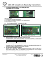
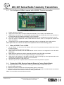
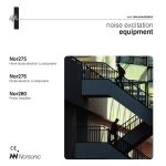
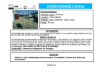
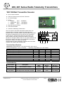
200, 201 Series Radio Telemetry Transmitters
‘200’ DIN Rail Transmitter Encoder
•
•
•
•
•
•
•
Up to 8 Input Channels
Volt Free contact Inputs via Screw Terminals
12 / 24Vdc Supply
Range;
433MHz
Up to
433MHz NB Up to
458MHz
Up to
200 Metres
1,000 Metres
6,000 Metres
High Security RF Protocol
Auto Transmit Mode
Automatic ‘Watchdog’ Transmission
This is a simple to use radio transmitter module which can
accept 8 pairs of ‘Volt free’ contacts as inputs via screw
terminals. When a contact closure occurs the 200Tx transmitter
will transmit a data packet over the RF link to an associated
210Rx receiver. (That has been learnt into the 200Tx) The
200Tx module continually monitors the status of its ‘inputs’.
Whenever a change of state is seen on any input the 200Tx will
transmit the status of all inputs. Full configuration instructions
are given in section 2.2 of the user manual.
The transmitter encoder uses EMC compliant radio transmitter
modules and complies with ETSI330-220
BNC Socket
I/P 1
I/P 2
Auto Tx
I/P 3
I/P 4
200Tx
Enable 1-8
8 / 15
I/P 5
I/P 6
I/P 7
I/P 8
RF Tx
12 / 24Vdc
Supply
8 x Zero Volt Inputs
Technical Specifications
Dimensions: Within DIN Rail: 112 x 82 mm (PCB: 109 x 72mm)
Storage Temperature; -10 to +70o Celsius.
Operating Temperature; 0 to +55o Celsius.
Electrical Characteristics
Min
Typical
Max
Supply Voltage: 12V Supply
10
12
16
Supply Voltage: 24V Supply
21
24
30
Antenna Output Lead Impedance
50
433MHz / 433NBMHz Version
Supply Current: Quiescent
10
Supply Current: Transmitting Data
150
170
200
458MHZ Version
Supply Current: Quiescent
10
Supply Current: Transmitting Data
240
250
270
Units
V
V
Ohms
mA
mA
mA
mA
Part Numbering
FM Transmitter, 8 inputs
Freq
(MHz)
433.92
Range**
(Metres)
200
Compatible
Decoders
210-433FR
FM Narrow Band Transmitter, 8 inputs
434.525
1,000
210-525NR
Part Number
Description
200-433FR
200-525NR
200-458FR
FM High Power Transmitter, 8 inputs
458.850
6,000
210-458FR
** Range stated is optimum, direct line of sight. In worst conditions this can be reduced by up to 50%
DS200-8 Feb ’04
©2004 RF Solutions Ltd, www.rfsolutions.co.uk
Tel 01273 898000 Fax 01273 480661
Page 1
200, 201 Series Radio Telemetry Transmitters
‘201’ DIN Rail Transmitter Encoder
•
•
•
•
•
•
•
•
•
Low Power Transmitter.
Designed for Battery Operation
Up to 8 Input Channels
Inputs via Volt free contact screw terminals or IDC
Connector
12 / 24Vdc Supply
Range;
433MHz NB Up to
458MHz
Up to
1,000 Metres
6,000 Metres
High Security RF Protocol
Zero Volt Inputs 1-8
Auto Transmit Mode
BNC Socket
Automatic ‘Watchdog’ Transmission
This is a simple to use 8 channel radio transmitter
module which can accept inputs via 8 pairs of ‘Volt free’
screw terminal contacts or two IDC connectors. When a
contact closure occurs the 201 transmitter will transmit
a data packet over the RF link to an associated 210Rx
receiver. (That has been learnt into the 201Tx) The
201Tx module continually monitors the status of its
‘inputs’. Whenever a change of state is seen on any
input the 201Tx will transmit the status of all inputs.
IDC Header
Inputs 1-4
I/P 1
I/P 2
Auto Tx
I/P 4
Enable 1-8
201Tx
I/P 5
I/P 7
8 / 15
IDC Header
Inputs 5-8
I/P 3
I/P 6
RF Tx
I/P 8
12 / 24Vdc
Supply
Zero Volt Inputs 5-8
The unit has exceptionally low power consumption, allowing for long battery-powered operation. Full
configuration instructions are given in section 2.2 of the user manual.
The transmitter encoder uses EMC compliant radio transmitter modules and complies with ETSI330220.
Technical Specifications
Dimensions: Within DIN Rail: 160 x 82 mm (PCB: 145 x 72mm)
Storage Temperature; -10 to +70o Celsius.
Operating Temperature; 0 to +55o Celsius.
Electrical Characteristics
Min
Typical
Max
Supply Voltage: 12V Supply
10
12
16
Supply Voltage: 24V Supply
21
24
30
Antenna Output Lead Impedance
50
Supply Current: Quiescent
60
Supply Current: Transmitting - 433MHz NB module
50
Supply Current: Transmitting - 458MHz module
180
Units
V
V
Ohms
nA
mA
mA
Part Numbering
Part Number
Description
Freq
(MHz)
Range**
(Metres)
Compatible
Decoders
201-525NR
FM Narrow Band Transmitter 8 inputs
434.525
1,000
210- 525NR
201-458FR
FM High Power Transmitter 8 inputs
458.850
6,000
210-458FR
** Range stated is optimum, direct line of sight. In worst conditions this can be reduced by upto 50%
DS200-8 Feb ’04
©2004 RF Solutions Ltd, www.rfsolutions.co.uk
Tel 01273 898000 Fax 01273 480661
Page 2
200, 201 Series Radio Telemetry Transmitters
1 Configuring a Remote Telemetry System
(200Tx/201Tx -> 210Rx)
There are three Steps:
1. Pre-Configure the 200 or 201 series transmitter
2. Pre- Configure the 210Rx to operate with a 200 or 201 series transmitter
3. Marry a 200/201Tx to a 210Rx
1.1
Pre-Configure a 200/201 Transmitter Encoder
1. Mapping the 200/201 Transmitter Inputs to the 210 Receiver Outputs
The Remote telemetry system automatically maps the 8 transmitter input channels to 8 receiver output
channels. The ‘8/15’ option link on the transmitter allows selection of channels 1-8 or 9-15 on the receiver.
200/201 Tx Option Link
Open
Connected
210 Rx output Channels
1–8
9 – 15
2. Enable Option Links (ENABLE 1-8)
The 200 and 201 Transmitters have eight ‘Enable’ Option links which must be fitted in order for the
corresponding input to be valid (otherwise the 210Tx will ignore it). This enables applications where many
transmitters are used with a single 210Rx (many to one relationship)
3. Auto Transmit with Watchdog Mode ‘Auto Tx’
When the ‘Auto Tx’ link is made, the 200/201 Tx automatically transmits its data once within every 5
second period, in addition, channel 16 is allocated as a ‘system watchdog‘. As long as the 210Rx
continues to receive this signal then output ‘16’ is held ON. If for any reason (fault or RF interference) the
signal is not received for approx 20secs then output ‘16’ will drop out.
DS200-8 Feb ’04
©2004 RF Solutions Ltd, www.rfsolutions.co.uk
Tel 01273 898000 Fax 01273 480661
Page 3
200, 201 Series Radio Telemetry Transmitters
1.2
Pre-Configure a 210Rx to operate with a 200/201 Tx series transmitter
1.
2.
3.
Ensure option link J8 is open.
Apply power to the 210Rx, All output LEDS flash alternately. This is factory reset default state.
Apply power to any 200 or 201 Tx and briefly operate any input by shorting any of the input terminals on
the transmitter (ensure Enable link is fitted!), to force a transmit.
4. The 210Rx. LED2 flashes 5 times to indicate that the 210Rx is now configured for use with 200 / 201Tx.
5. Each time power is applied the 210Rx, LED2 flashes 5 times to show it is configured to operate with
200Tx transmitters.
6. Configuration is now complete and 200/201 transmitter unit(s) can be learned to the 210Rx receiver.
Note: Option links LK 1-16 have no affect on the operation of the remote telemetry system.
1.3
1.
2.
3.
4.
5.
6.
7.
8.
Marry a 200/201 Tx to a 210Rx
On the 200/201 Tx, remove the Link header ‘OPT1‘ (auto Tx). (prevents automatic transmission during
the learn process).
On the 210Rx Ensure option link J8 is open.
Apply power to the 210Rx, note that LED2 flashes 5 times to show it is configured for use with 200Tx
transmitters.
Briefly press the 210Rx Learn Switch: Note that the 210Rx Learn LED (LED 17) will flash.
Wait until the 210Rx Learn LED has stopped flashing but is still illuminated.
Apply power to any 200/201 Tx and briefly operate any input by shorting any of the input terminals on the
Transmitter (ensure Enable link is fitted!), to force a transmit.
Note that the 210Rx learn LED will turn off.
The learn cycle is now complete and the transmitter/encoder will operate the systems.
1.4
Erasing the 210Rx Receiver Outputs (Return to Factory Default State)
1.
2.
3.
4.
To completely erase the 210Rx decoder’s memory, press and hold the 210Rx learn switch.
The learn LED will illuminate
Hold the learn switch until the learn LED extinguishes (approx 10 seconds).
Release the learn button and all the output LED’s will now flash alternately to indicate that all encoder data
has been erased and the 210Rx has returned to factory default state.
Note: It is not possible erase individual transmitters.
DS200-8 Feb ’04
©2004 RF Solutions Ltd, www.rfsolutions.co.uk
Tel 01273 898000 Fax 01273 480661
Page 4
200, 201 Series Radio Telemetry Transmitters
1.5
Connecting output Modules to the 210 Receiver
A range of ‘200’ series output modules are available which can be plugged into the 210 Receiver via the four
IDC header boxes on the receiver. The selection of output module will be dependant on the application. Please
see DS200S-1 for a summary the available modules.
1.6
Connecting an Antenna
The 210Rx has a 300mm flying lead cable (50ohm) with a panel mount BNC socket provided to mount on an
enclosure. This cable may be extended however please note that typically there is a 50% range reduction
with every 3metres of coax cable used!
For increasing range performance a +3dB gain antenna is available. This is supplied with wall mounting
bracket and 2metres of coax cable, it plugs in directly to the 210Rx BNC connector.
1.7
Range
The antenna choice and position directly controls the system range. Keep it clear of other metal in the system.
The best position by far, is protruding from the top of the product. This is often not desirable for practical or
ergonomic reasons and thus a compromise may be needed. If an internal antenna must be used then try to
keep it away from other metal items, and in particular large ones like transformers, batteries and PCB tracks
and earth planes.
Note that the space around the antenna is as important as the antenna itself. All radio systems are dependant
on a radio signal being received through airspace.
The range quoted is the optimal in direct line of sight without obstacles and in good atmospheric conditions.
Range is affected by many things, for example local environmental conditions, atmospheric conditions,
interference from other radio transmitters. For evaluating the local environment please see our RF Meter
(DS006)
In very worse case applications the range quoted may be reduced to 30% of the optimal range stated.
1.8
Signal integrity
In systems where many encoders are in close proximity there may be occasions when, due to signal overlay
between encoders, it is difficult or impossible to guarantee system integrity. In such circumstances it is the
responsibility of the installer to ensure that the system performance is adequate for the purposes of the
installation.
1.9
Information availability
All products are supplied with their relevant datasheets. These are also available for download from the website
or on request from RF Solutions Ltd.
R. F. Solutions Ltd.,
Unit 21, Cliffe Industrial Estate, South Street, Lewes,
E. Sussex, BN8 6JL, England
Tel +44 (0)1273 898 000
Email [email protected]
Fax +44 (0)1273 480 661
http://www.rfsolutions.co.uk
RF Solutions is a member of the Low Power Radio Association
All Trademarks acknowledged and remain the property of the respected owners
Information contained in this document is believed to be accurate, however no representation or warranty is given and R.F. Solutions Ltd. assumes no liability with respect to the accuracy of such information.
Use of R.F.Solutions as critical components in life support systems is not authorised except with express written approval from R.F.Solutions Ltd.
DS200-8 Feb ’04
©2004 RF Solutions Ltd, www.rfsolutions.co.uk
Tel 01273 898000 Fax 01273 480661
Page 5