1
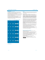
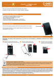
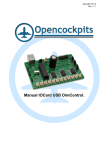
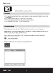
TR-8
Sintesis BCD Controller.
Recorder / player- 32 messages of 3,2 sec and 4 priority messages of 4,4 sec.
Recorder / Player of 32 messages of 3,2 sec. which can be controlled by BCD signals, and 4 priority
messages more of 4,4 sec. with controlled by negative-going clock transition.
It has a direct output to a loudspeaker with maximum power of 5 W. as well as volume control.
Control inputs at 24 Vdc, opto-coupled with electrical insulation.
It accepts the auto repeat function of each message.
It also includes an inhibition input, a microphone, operating indicators Leds, play, rec, run and repeat.
TECHNICAL CHARACTERISTICS.
Voltage : 24 VDC (50-60 Hz).
Min./max. Consumption: 80mA / 140mA.
Control Inputs signals: 3 up to 24 VDC.
Minimum Inputs control current: 10 mA
Sampling Frequency : 8 KHz.
Output Impedance : 4 8 Ohms.
Output power : 5W. (RSM at 4 Ohms).
Automatic Gain Control : It can be selected by a jumper placed on the circuit.
Protection against polarity inversion Voltage input.
Operating temperature: -25ºC à +55ºC
Max. wire diameter for connection terminals : 2,5 mm.
Net weight: XXXX g.
Fixing : DIN-Rail / screws with fixation in 4 points
Indicator for Operating mode : 5mm Red Led, (PWR)
Indicator for recording selection: Led 5mm Red, (REC).
Indicator for Playing selection: 5mm Green led, (PLAY).
Indicator for Activation function : 5mm Green Led, (RUN).
Indicator for Repeat Messages mode: 5mm Orange Led, (REPEAT).
Rules, EMC Electromagnetic Compatibility 89/336/CCE as well as
its modifications 32/31/CEE and 93/68/CEE.
Duplicats dels punts: -3,12 mm.
Duplicat de cada Característica per model: -20 mm.(relés), -22,5 (Transistors)
TR-8
INSTRUCTIONS.
Description.
Power Supply.
The TR-8 module has 5 inputs indicated as ABCDE and controlled by
binary signal from 3 up to 24 V dc. Thanks to the correspondent binary
combination, the 32 resulting messages can be recorded or played,
during a maximum time of 3,2 sec for each one. All inputs can be
inhibited thanks to an independent input.
The module also includes 4 supplementary inputs, numerated from 1
up to 4, which can be directly activated by a 24 Vdc positive signal and
with a priority play regarding any other previous selection or a selection
at the same time. The maximum capacity accepted by these
supplementary inputs is 4,4 sec.
The device incorporates a volume control, a push button as well as a
microphone for recording.
The module's feed, independently of the feed used for control inputs,
has to be done through a 24 VDC voltage perfectly stabilized; for that,
we strongly recommend you to use a short-circuit power supply with a
low ripple level. Do never use standard a power supply, neither
rectifiers, who can damage the module operating mode.
Note: To be in accordance with the EEC regulations, a switch and a
200 mA fuse have to be installed on the positive of the feed input.
Both are necessary for the module's protection.
Installation.
The module's installation has to be preferably done into an enclosure or
a rack, correctly ventilated, avoiding any contact between the circuit
and metal objects.
Do not install the device in humid places, under high temperatures, or in
contact with liquids.
Do not supply the module before to finish its installation. Please
carefully read this instruction manual.
Control Signals. Composed by 11 connection inputs (5 x BCD, 4
priority, 1 inhibition and the negative), they are electrically insulated
from the rest of the circuit. For this reason, it is necessary to connect
the negative of the signal with the signal which had to excite inputs and
the common negative of control inputs.
It is recommended to minimize at the maximum, the cable length for
theses inputs, using if possible shielded cable.
Loudspeaker Output. The maximum power supplied by the module is
5 W. It is better to use a loudspeaker with a minimum of 10W. with an
impedance from 4 up to 8 Ohms. For this output, you can use a
standard shielded cable.
Suggestion. The device has 4 holes of 3.5 mm to be fixed. More over,
thanks to Cebek C-7587 guides, it can be install in a DIN-RAIL.
Pag. 1/3
Recording.
To configure the device in recording mode, you have to put in ON
position the switch Nº3 of the battery for the functions control, and the
REC Led will light.
Then, you have to select the number of the message in which you
want to make the recording. See paragraph “To activate control
signals”. Pressing the push button “push”, and during its pressure, the
module will record through the microphone. If you stop to press the
push button, or if you exceed the maximum allowed time by the
message, the recording will automatically stop.
During the recording process, the RUN Led will intermittently light
from the beginning to the end.
AGC. The module has an Automatic Gain Control (AGC), which
allows to stabilize the signal level received by the microphone. To
activate the AGC function, the ON jumper has to be closed or joined.
At the opposite, to deactivate this function, the OFF jumper has to be
closed or joined.
Attention: Both jumpers can never be closed at the same time.
The device is supplied with the AGC function activated, mode that we
suggest to maintain.
Specifications to record. Before to start to record, it is better to
reduce at the maximum the volume control, to be close to the
microphone and to clearly speak.
Rev. 0402
Sintesis BCD Controller.
Cebek TR-8
INSTRUCTIONS.
To activate the Control signals.
Playing.
The activation of the inputs control signals is done by high level
(positive between 3 and 24 VDC), regarding thecommon negative of
these inputs. It is necessary to connect this negative to the negative of
the control signal that you want to excite inputs.
To select the message between 0 and 31 has to be done in BCD, where
the terminal E correspond to bit with the higher weight (Msb) and the
terminal A to the lower weight (Lsb).
The four priority messages are activated by direct application of the
signal at high level, following a hierarchical order; the Nº1 being the
more important and the Nº4 being the less important.
The inhibition signal (INH) prevent the recording and the playing of
messages (from 0 to 31) if the signal is maintained at high level. It
never affect the four priority messages.
The operating TR-8 module in playing mode requires that the switch
Nº3 of the function control battery is maintained in OFF position. The
PLAY Led will light.
To activate the control signals (message Selection).
INH Activated Message
Repetitive Playing. The module allows to play a message in a
repetitive and constant mode till this one is selected. If the switch Nº1
is placed in ON position, the repetitive play is activated for priority
messages. For messages from 0 till 31, if you place the switch Nº2 in
ON position, the repetitive mode. When these switches are in OFF
position, the correspondent repetitive function will be deactivated.
The REPEAT Led will light when the repetitive playing is activated for
priority messages as well as for message 0 to 31. It will light off if the
repetitive function is not assigned to any kind of these messages.
Playing. Messages from 0 to 31 are activated according to the binary
code introduced into the corresponding control inputs. Nevertheless,
the playing won't be activated till the inhibition input (INH) is not at a
low level. Then, the module will play the message corresponding to
the introduced binary code. When the message is finished, if the
repetitive option is activated and if the same binary code is
maintained, the message will be played an other time. The cycle will
be maintained, till you change the binary code or the INH input reach
a high level.
If the playing is “Normal” (without repetition), the message will be
played only one time, even if you maintain the signal of the code into
control inputs.
We recommend you to maintain the INH input at high level when you
change the selection of the binary code or after the activation of a
normal playing; otherwise with the INH at low level and all inputs
opened, the message Nº0 will be selected.
If a priority message is selected, the circuit will automatically stop any
message playing and start to play the priority message.
If several priority messages are selected at the same time, the
module will play only the message with higher hierarchical order. (See
“To activate Control Signal” paragraph).
A
B
C
D
E
1
2
3
4
X
X
X
X
X
0
0
0
0
1
Aucun
X
X
X
X
X
1
X
X
X
X
Priorité 1
X
X
X
X
X
0
1
X
X
X
Priorité 2
X
X
X
X
X
0
0
1
X
X
Priorité 3
X
X
X
X
X
0
0
0
1
X
Priorité 4
0
0
0
0
0
0
0
0
0
0
Message 0
1
0
0
0
0
0
0
0
0
0
Message 1
0
1
0
0
0
0
0
0
0
0
Message 2
1
1
0
0
0
0
0
0
0
0
Message 3
0
0
1
0
0
0
0
0
0
0
Message 4
1
0
1
0
0
0
0
0
0
0
Message 5
0
1
1
0
0
0
0
0
0
0
Message 6
1
1
1
0
0
0
0
0
0
0
Message 7
0
0
0
1
0
0
0
0
0
0
Message 8
1
0
0
1
0
0
0
0
0
0
Message 9
0
1
0
1
0
0
0
0
0
0
Message 10
1
1
0
1
0
0
0
0
0
0
Message 11
Warranty and Technical Incidences
0
0
1
1
0
0
0
0
0
0
Message 12
1
0
1
1
0
0
0
0
0
0
Message 13
0
1
1
1
0
0
0
0
0
0
Message 14
1
1
1
1
0
0
0
0
0
0
Message 15
0
0
0
0
1
0
0
0
0
0
Message 16
1
0
0
0
1
0
0
0
0
0
Message 17
0
1
0
0
1
0
0
0
0
0
Message 18
1
1
0
0
1
0
0
0
0
0
Message 19
0
0
1
0
1
0
0
0
0
0
Message 20
All cebek modules have a total warranty of 3 years as concern
components and labour man.
All damage, error or mistake due to problems independent from the
circuit, connection, installation or operating mode, as well as wrong
handling are not included in this warranty. More over it will be
necessary the purchase invoice of this module for any claim.
This manual (documentation) can be reviewed or modified without any
preavis, and it doesn't involve FADISEL. S.L.
The use of any of the FADISEL modules' mentioned in this manual
provoke the acceptation of these commercial terms and
correspondent warranty.
1
0
1
0
1
0
0
0
0
0
Message 21
0
1
1
0
1
0
0
0
0
0
Message 22
1
1
1
0
1
0
0
0
0
0
Message 23
0
0
0
1
1
0
0
0
0
0
Message 24
1
0
0
1
1
0
0
0
0
0
Message 25
0
1
0
1
1
0
0
0
0
0
Message 26
1
1
0
1
1
0
0
0
0
0
Message 27
0
0
1
1
1
0
0
0
0
0
Message 28
1
0
1
1
1
0
0
0
0
0
Message 29
0
1
1
1
1
0
0
0
0
0
Message 30
1
1
1
1
1
0
0
0
0
0
Message 31
To contact our technical depart. Please contact:
[email protected] or by fax (+34) 93.432.29.95 or by mail at the
following address: c/Quetzal, 17-21. (08014), Barcelona - SPAIN
X = High or Low level.
1 = High level. (3 - 24 V. D.C.).
0 = Low level. (0 V. D.C.).
Pag. 2/3
Rev. 0402
Sintesis BCD Controller.
Cebek TR-8
ELECTRICAL DIAGRAM.
MECHANIZING and CONNECTIONS.
107 mm.
100 mm.
C26
TR-8
ASRAUPCAM 8-RT
COMP
IC2
C27
C28
PWR
VOLUME
RUN REPEAT
REC
C20
PLAY
IC6
C21
R4
C23 R13
D13
R8
R7
R6
R5
+ 24V. D.C.
Power Supply
R28
D2
C19
SPEAKER
C22
Loudspeaker Output
4 - 8 W / 5W.
SPK
R12
Volume Control
PUSH
IC1
POWER
R14
C18
IC7
C24
Record Push Button
C1
C12
C25
C17
C2
R31
R9
R33
R29
R11
C14
P/R
C7
ON
OFF
C11
C8
IC5
XT1
98,75 mm.
C3
C10
Jumper AGC
Automatic Gains
Control
91,7 mm.
Dips Switches
Functions Control
ACG
Microphone
Control Signal Negative Input
Inhibition Input
1
E
IC12
D
BCD
C
IC11
B
R10
MIC
IC9
A
R16
PRIORITY
3
2
IC13
C16
R19
R18
R17
4
R32
R21
R25
COM INH
R24
R23
R22
TR-8
IC18
R30
R20
C9
SET
C15
Inputs
BCD Input
Priority Messages Message Selection 0 till 31
Control Signals
Pag. 3/3
Rev. 0402