1
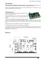
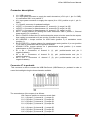
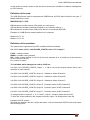
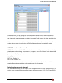
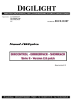
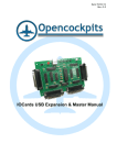
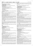
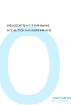
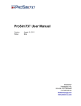
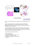
Date:08/18/15 Rev.:1.1 Manual IOCard USB DimControl. IOCard USB DimControl Manual Index: MANUAL IOCARD USB DIMCONTROL...................................................................................................... 1 INDEX:.......................................................................................................................................................... 2 INTRODUCTION: ......................................................................................................................................... 3 USB DIMCONTROL: ..................................................................................................................................... 3 ESCHEMA:................................................................................................................................................... 3 CONNECTOR DESCRIPTION: ......................................................................................................................... 4 Connector J7 to pedestal:..................................................................................................................... 4 OPERATION OF THE CARD:...................................................................................................................... 5 USB MODE FOR INDEPENDENT SOFTWARE. .................................................................................................. 5 USB MODE WITH SIOC. ............................................................................................................................... 6 Definition of the card:............................................................................................................................ 7 Definition of the variables: .................................................................................................................... 7 NO USB OR STANDALONE MODE. ................................................................................................................ 8 Potentiometer for each channel: .......................................................................................................... 8 Master potentiometer for three channels:............................................................................................. 9 CARD OPERATIONS: .................................................................................................................................... 9 LINKS OF INTEREST: ................................................................................................................................. 9 www.opencockpits.com 2 IOCard USB DimControl Manual Introduction: This board allows controlling the backlight brightness of the panels and / or modules using software and hardware depending on the computer or completely independently. It has 3 control modes: USB mode; with a master potentiometer for all channels and by individual potentiometers for each channel. Usb DimControl: This board controls 3-channel supply with 4 outputs for each channel using PWM control. The board supports up to 50 Volt power, each output supports up to 1 Amp with a limit of 2.5 Amps between all outputs. The card can be configured with dedicated software via USB and store in internal eprom memory the applicable maximum power for each channel and the power used by default when connecting. Variables can also be programmed using SIOC IOCP code. Using potentiometers, each channel can go from 0 to MAX linearly. The card mode 3 doesn't need to be connected to the USB port. Once configured, the plate can increase and decrease the brightness of the 3 channels at once, automatically managing the different intensities of each channel and being able to control different types of LEDs or bulbs. Schema: www.opencockpits.com 3 IOCard USB DimControl Manual Connector description: J1 = USB connector. J2 = Input power connector to supply the card's electronics (+5V in pin 1, pin 2 = GND), it is used when SW1 is on position 3. J6 = Input power connector to supply the outputs (0 to +50V, positive on pin 1, pin 2 = GND). J7 = Specific connector for pedestal backlight. J3/POT1 = Connector for potentiometer nº1, channel A (1), range 0 to 255. J4/POT2 = Connector for potentiometer nº2, channel B (2), range 0 to 255. J5/POT3 = Connector for potentiometer nº3, channel C (3), range 0 to 255. SW1 = Jumper selector for feeding the card's electronics. USB = position 1, External power supply (5V) = position 3. SW2 = Closed if we want the 5V card's electronics power to be the same for the outputs, then nothing is connected to J6 (we use the J2 power for the outputs). NO USB/USB = Jumper selector for USB mode (position 3) or standalone mode (position 1). NO POTS/POTS = Jumper selector for potentiometer mode (position 3) or not (position 1), its used in combination with the previous selector. NO/LINK POTS= Jumper selector for 3 potentiometer mode (position 1) or master potentiometer on POT1 (position 3). S1 a S4 = Connectors of channel A (1), pin1 positive/anothe and pin 2 negative/cathode). S5 a S8 = Connectors of channel B (2), pin1 positive/anothe and pin 2 negative/cathode). S9 a S12 = Connectors of channel C (3), pin1 positive/anothe and pin 2 negative/cathode). Connector J7 to pedestal: This connector is able to connect the USB DimControl (USB-Dimmer) to pedestal in order to control the backlight using the three channels available. The nomenclature of the outputs is as follows: VM: Common positive or common anode feed. O,1,1: (O)utput, (1) channel A, (1) output S1. O,1,2: (O)utput, (1) channel A, (2) output S2. O,1,3: (O)utput, (1) channel A, (3) output S3. O,1,4: (O)utput, (1) channel A, (4) output S4. O,2,1: (O)utput, (2) channel B, (1) output S5. O,2,2: (O)utput, (2) channel B, (2) output S6. O,2,3: (O)utput, (2) channel B, (3) output S7. www.opencockpits.com 4 IOCard USB DimControl Manual O,2,4: (O)utput, (2) channel B, (4) output S8. O,3,1: (O)utput, (3) channel C, (1) output S9. O,3,2: (O)utput, (3) channel C, (2) output S10. O,3,3: (O)utput, (3) channel C, (3) output S11. O,3,4: (O)utput, (3) channel C, (4) output S12. This connector can be used like the simple outputs "Sxx". Operation of the card: The board power (5V) can be done from the USB bus itself with SW1 at position 1 or external 5V supply connected to J2 with SW1 at position 3. If the lighting power exceeds 5V, SW2 is left open and the outputs are fed on J6 with up to 50V. If lighting power is 5V and it is wanted to use the same external source of card's electronics, we close SW2 and do not connect anything to J6. Importantly, the outputs will be different for each channel according to their limits, which will depend on the programming done in either USB modes available. The card has three operating modes, see each of them. USB mode for independent software. The USB DimControl card independent USB mode is able to control all parameters of the card via USB connection to your computer with a specific downloadable program (iocard_dimcontrol.exe) via Web on Opencockpits aid page and from the same download page of the product, without using SIOC. The jumpers settings for this mode are: NO USB: Position 3. NO POTS: Position 1. POTS LINK: Position 3. When the card is plugged into the computer it is immediately recognized by the control software iocard_dimcontrol.exe which reads the default values stored in the EPROM: www.opencockpits.com 5 IOCard USB DimControl Manual Once loaded the defaults, we can change the output value of each channel independently using sliders. We can also change the maximum power output of each channel and store it in the EPROM if you press the button UPDATE LIMITS. The range is 256 steps. These steps have zero to the maximum power of the card, i.e. if the maximum power of channel A is 40, the value of enlightenment never pass 40 although there remain more steps on the potentiometer or on the iocar_dimcontrol.exe software sliders. Establishing of limits is very important and can only be done from USB mode either independently or with SIOC (version 4.7B1 or higher). USB mode with Sioc. The dependent on SIOC USB mode is to control all parameters of the card using either IOCPConsole management or using a script. The version that recognizes the USB DimControl card is the up 4.7B1, downloadable from the Opencockpits aid web and from the same download page of the product. The jumpers settings for this mode are: NO USB: Position 3. NO POTS: Position 1. POTS LINK: Position 3. When the card is connected to the computer it is immediately recognized by SIOC: www.opencockpits.com 6 IOCard USB DimControl Manual In this mode we need a script to link the card to access the variables of channel management by IOCPconsole. Definition of the card: The USB DimControl card is recognized as USB-Dimmer by SIOC and to define it the type 17 Master definition is used: MASTER=XX,17,YY,ZZ XX indicates the index number (IDX) within our cards group. YY indicates the number of devices installed in our computer fixed to 1. ZZ indicates the number of the USB port to which it is connected (DEVICE). Example of 2 USB Dimmer cards installed in our computer: Master=0,17,1,70 Master=1,17,1,83 Definition of the variables: The card access is performed by IOCP variables defined as follows: Var VVVV, name NNNN, Link IOCARD_CONFIG, device DD, Output S VVVV = variable number. NNNN = variable name (optional). DD = index number defined on sioc.ini (if we have declared as 0: no need to put the reference to the number of Device). S = number of output. The variables which manage the card by IOCP are: Var 0001, Link IOCARD_CONFIG, Output 1 // =98 to can set the outputs values =99 to save the limits of each channel Var 0002, Link IOCARD_CONFIG, Output 2 // Maximum Value Channel A Var 0003, Link IOCARD_CONFIG, Output 3 // Maximum Value Channel B Var 0004, Link IOCARD_CONFIG, Output 4 // Maximum Value Channel C Var 0005, Link IOCARD_CONFIG, Output 5 // Intensity value (0-255) Channel A Var 0006, Link IOCARD_CONFIG, Output 6 // Intensity value (0-255) Channel B Var 0007, Link IOCARD_CONFIG, Output 7 // Intensity value (0-255) Channel C To assign values to outputs 2, 3, 4, 5, 6 and 7, output 1 (Output1) takes the value 98. To save the values entered in the outputs and limits, output 1 is assigned the value 99. Example of IOCP control: We keep the definition text as a script and load it, click on the button IOCPConsole and shows the following screen. www.opencockpits.com 7 IOCard USB DimControl Manual From this screen you can manage the maximum values of each channel and output values. We select the variable V0001 and give it value 98 to assign data to channels and limits, then we can select each output and assign the desired value and finally, to save the data, we send value 99 to V0001. With these two ways we can do three things, program the values with the independent software, another using a script to handle other definitions and leave the card in standalone mode. NO USB or standalone mode. USB DimControl iocard NO USB mode is able to control all parameters of the card using potentiometers without being connected to a computer, except the limits of each channel that need to be set up by one of the above two methods. The jumpers settings for this mode are: NO USB: Position 1. POTS NO: Position 3. POTS LINK: position 1 or 3. In this way we have two sub-modes, one with control values of each channel with its own potentiometer and another with a single potentiometer for all channels. Potentiometer for each channel: For each channel having its own output value management, POTS LINK selector must be in position 1 and a potentiometer connected to each channel connector (POT1, POT3 and POT2). www.opencockpits.com 8 IOCard USB DimControl Manual Master potentiometer for three channels: This mode provides a change of output values with a single potentiometer for all channels. The POTS LINK selector must be in position 3 and the master potentiometer on the POT1 connector. In this way the full range of the master potentiometer will adapt to the useful zone set on each channel. Card operations: It should be noted some connotations of USB DimControl card If you connect a heavy load on the outputs may be a drop in the supply voltage, so that adequate feed must be taken into account. The card is suitable for connecting LEDs and bulbs in series and parallel with their respective resistors if needed. It is advisable to feed the outputs with the maximum withstand voltage for the LEDs and / or bulbs to have a good resolution in the range of control. Be very careful with the limits assigned to each channel and its outlets to avoid melting LED and/or bulbs. Remember that having the limits saved in the EPROM, the values will not rise beyond them though the potentiometer do all the way. This ends this manual, we invite you to read the manuals of the others Opencockpits elements and explore the SIOC software. We thank You for trusting us. Links of interest: Support zone for customers: http://www.opencockpits.com/catalog/info/ www.opencockpits.com 9