1
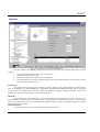
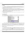
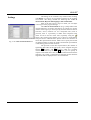
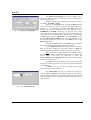
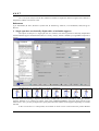
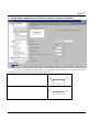
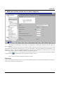
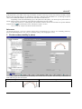
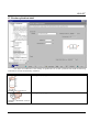
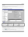
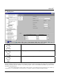
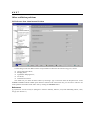
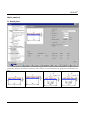
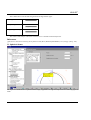
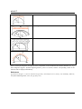
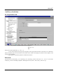
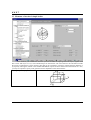
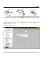
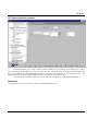
SCAD Soft
Structure CAD software system
for
Windows 95/98/NT
KUST
Oscillations, Stability, Statics
Version 1.1
User manual
UDC 539.3+624.014
Team of authors
S.V. Girenko, E.Z. Kriksunov, A.V. Perelmuter, M.A. Perelmuter, S.Y. Fialko
«KUST». Oscillations Stability Statics. USER MANUAL. Version 1.1.
The manual contains a description of the functionality of the KUST software, its technologies, and
recommendations on its usage.
The software is oriented at engineers and designers who have basic skills with personals
computers.
© SCAD Soft, 2004
TABLE OF CONTENTS
GENERAL INFORMATION.................................................................................................................................... 5
INTERFACE............................................................................................................................................................... 6
CONTROLS................................................................................................................................................................ 8
SETTINGS ................................................................................................................................................................ 10
STABILITY OF EQUILIBRIUM........................................................................................................................... 12
1.
2.
3.
4.
5.
6.
7.
8.
9.
10.
11.
12.
13.
14.
15.
16.
17.
18.
19.
20.
SINGLE-SPAN UNIFORM-SECTION BARS ON STIFF SUPPORTS ........................................................................ 12
SINGLE-SPAN BARS ON ELASTICALLY DISPLACEABLE OR INCLINABLE SUPPORTS ......................................... 13
SINGLE-SPAN VARIABLE-SECTION BARS ON STIFF SUPPORTS............................................................................ 14
SINGLE-SPAN STRAIGHT BARS OF UNIFORM SECTION ON ELASTIC FOUNDATION .......................................... 16
MULTI-SPAN UNIFORM-SECTION BARS ON ELASTIC SUPPORTS ..................................................................... 18
CIRCULAR RING............................................................................................................................................... 19
CIRCULAR ARCHES (STABILITY IN PLANE)....................................................................................................... 20
PARABOLIC ARCHES (STABILITY IN PLANE)..................................................................................................... 22
SHALLOW TWO-HINGED ARCHES (STABILITY IN PLANE) ................................................................................. 23
STABILITY OF PLANE FLEXURE OF THIN-WALLED BEAMS ................................................................................ 24
RECTANGULAR PLATE ..................................................................................................................................... 25
ROUND PLATE ................................................................................................................................................. 26
SKEW PLATE ................................................................................................................................................... 28
CYLINDRICAL PANEL ....................................................................................................................................... 29
CONICAL PANEL .............................................................................................................................................. 30
SPHERICAL PANEL ........................................................................................................................................... 31
CIRCULAR CYLINDRICAL SHELL....................................................................................................................... 32
ELLIPTIC CYLINDRICAL SHELL ......................................................................................................................... 34
TRUNCATED CIRCULAR CONICAL SHELL ......................................................................................................... 35
SPHERICAL SHELL ........................................................................................................................................... 36
NATURAL OSCILLATION FREQUENCIES...................................................................................................... 37
21.
22.
23.
24.
25.
26.
27.
28.
29.
SINGLE-SPAN UNIFORM-SECTION BARS ON STIFF SUPPORTS ............................................................................. 37
SINGLE-SPAN BARS ON ELASTIC FOUNDATION ................................................................................................. 38
BARS OF VARIABLE SECTION............................................................................................................................ 39
ROUND RINGS .................................................................................................................................................. 40
STRINGS .......................................................................................................................................................... 41
RECTANGULAR PLATES .................................................................................................................................... 42
ROUND PLATES ................................................................................................................................................ 44
CYLINDRICAL SHELL........................................................................................................................................ 45
CONICAL SHELL ............................................................................................................................................... 46
OTHER OSCILLATION PROBLEMS ................................................................................................................. 47
30. REFERENCE DATA ABOUT INTERNAL FRICTION ................................................................................................ 47
STATIC ANALYSIS ................................................................................................................................................ 48
31. ROUND PLATES ................................................................................................................................................ 48
32. RECTANGULAR PLATES .................................................................................................................................... 51
KUST
33. SPHERICAL DOMES ........................................................................................................................................... 52
AUXILIARY CALCULATIONS ............................................................................................................................ 54
34.
35.
36.
37.
38.
39.
4
POLYNOMIAL ROOTS ....................................................................................................................................... 54
MOMENTS OF INERTIA OF SIMPLE BODIES ......................................................................................................... 55
GEOMETRICAL PROPERTIES ........................................................................................................................... 58
DETERMINANT OF MATRIX ............................................................................................................................... 60
INVERSE MATRIX.............................................................................................................................................. 61
LINEAR EQUATION SYSTEMS ........................................................................................................................... 62
KUST
General information
The reference manual program KUST is developed by the SCAD Soft company and included in the
SCAD Office software package. It solves particular classes of mechanical problems for which there exist
analytical or sufficiently accurate approximate solutions published in literature on the subject.
Though the majority of these problems can be also solved by the SCAD software, involving KUST will
enable one to get a solution without building any design finite-element models. Also, some of results obtained by
KUST can be used to specify source data when building a finite-element model (such data as coefficients of
effective length, estimates of natural frequencies etc.).
All problems which the program is capable of solving can be classified into the following categories:
♦ stability of equilibrium;
♦ frequencies of natural oscillations;
♦ other oscillation problems;
♦ static calculations;
♦ auxiliary calculations.
Formulations of most of the problems in question are quite clear, therefore for each problem this manual
gives only brief statements, lists of source data needed, and results to be obtained by solving it. More details can
be found in literature referred to in each section.
5
KUST
Interface
Fig. 1. The main window of the KUST program
The main window of the KUST program has the same set of controls in all working modes; these controls
include:
•
•
•
•
a tree of problems used to select a type of the analysis;
edit fields to specify source data;
fields where results of the analysis will be displayed;
functional buttons to activate the analysis and invoke various control actions (start the analysis, form a
report, open the reference help, …).
Problem tree
The problem tree has three levels of hierarchy. The first, highest, level contains names of problem groups
such as STABILITY OF EQUILIBRIUM or NATURAL OSCILLATION FREQUENCIES. The second level
contains types of constructions such as Bars, Plates; the third level suggests particular problems. To invoke a
problem type, place the mouse pointer onto its title and left-click.
Edit fields
When editing data in the edit fields, you can enter numbers as fixed-point values (such as 0.214) or in a
scientific notation (such as 1.23е5). The integer and the fractional parts are separated by a period. A comma can be
used, too, but this must be set up in the Windows environment settings. The data entered in the fields are checked
when the analysis is activated.
Functional buttons
Functional buttons are used to invoke the following control actions:
6
KUST
Calculate to invoke actions of source data checking and performing the calculation itself;
Report to form a report containing results of the calculation/analysis;
Settings to activate a program setup mode (see below);
Help to get reference help information about KUST;
Fig. 2. The
Search the problem tree dialog box
Find to search the problem tree for a context in a problem’s name.
The search is done using the Search the problem tree dialog box
(Fig. 2) where you should specify a text to search for and click the
Find button. This will open a list of all problems the titles of which
contain the specified text in the Search results list. Place the
mouse pointer onto the desired problem and click the Go to button;
the focus of the tree will switch to the problem pointed to. To
proceed with the analysis, close the search dialog box.
Exit to end the active working session and exit the program.
Calculate
To perform the calculation, select a problem in the problem tree, specify source data for it in the edit fields,
and click the Calculate button.
7
KUST
Controls
Principles of control implemented in the software are intended to provide the unified dialogue functions.
This software uses a common dialog box technique. The following controls and ways of data access are used:
♦ functional buttons “clicking” which (by placing the mouse pointer onto a button and clicking the left mouse
button) takes you to particular modes or actions;
♦ selection tools of various kinds which enable you to choose one or more of suggested options;
♦ data edit fields using which you specify source data for the analysis. Source data consist of numbers. If a noninteger number is entered, its integral and fractional parts are separated with a period or another separator. The
separator is assigned by the user during the setup of the operating system (see Settings | Regional Settings |
Number). Number can be entered also in the scientific notation, for example, as 1.56e-7;
♦ drop-down and static lists from which to select data;
♦ tables to enter or display tabular information;
♦ dynamically digitized diagrams that display values of functions for an argument pointed to by the mouse
pointer on the screen.
Material properties
Many of the problems solved by KUST require you to specify physical properties of materials that a
structure is made of. In most cases this information can be specified in a unified way. There is a drop-down list (see
Fig. 3) from which you can choose the desired material.
Fig. 3. The Materials drop-down list.
When you select a material in the list, all properties will be retrieved from a database shipped with the
software. To check your selection, the program will display the properties of the selected material (such as the
elasticity modulus, Poisson ratio etc.). If you select the bottom item of the list, “OTHER MATERIAL”, the
respective edit fields will be enabled so that you can enter mechanical properties of the material absent in the
database manually. Before doing the analysis, the program will check the correctness of the information entered (for
example, no Poisson ratio greater than 0.5 can be specified).
Moments of inertia
In many cases (when a bar structure in under consideration) the source data for the analysis include
moments of inertia of a cross-section. If the structure is made of standard rolled stock, the specification of those data
. This will open a dialog box (see Fig. 4) that contains a tree
is simple. There is a service activated by the button
of rolled profiles. Having selected a desired profile, the user will get the information about the moments of inertia
with respect to the Y and Z axes of the selected profile (the X axis is assumed to be collinear with the bar’s axis).
Clicking one of the Apply buttons located near Iy and Iz will put the moment of inertia information automatically to
8
KUST
the respective edit field.
Fig. 4. The Select stiffness dialog box
9
KUST
Settings
Fig. 5. The Units of measurement tab
1 0
This dialog can be invoked at any moment when working
with KUST. It is used to set up general properties of the working
environment. The dialog contains the following tabs: Units of
measurement, Reports and languages, and Visualization.
Each of the tabs opens a page on which you can adjust
certain types of the program settings.
The Units of measurement tab (Fig. 5) helps define units
of measurements to be used in the analysis. It contains two groups
of data. The first group is used to specify units that measure sizes of
structures, forces, moments etc. For compound units (such as
pressure), there is a possibility to define their component units
(those for forces and for linear sizes) separately using the
button. The second group enables you to choose a representation
and precision for numerical data. Special controls are used here to
select data representation formats. Make sure to specify the amount
of significant digits in either the fixed-point decimal representation
or the floating-point scientific notation.
The precision of the data representation (the number of
significant digits after the decimal point) can be assigned using the
(decrease) and
(increase), while the scientific
buttons
notation is turned on by the button
. Also, you can specify in
respective edit fields what value of a unit of measurement should be
treated as “very small”, so quantities less than that by their absolute
magnitudes will be displayed as 0 in all visualizations.
KUST
Fig. 6. The Report and languages tab
The Report and languages tab (Fig. 6) enables you to
choose a language in which to represent all texts in dialog boxes
and to generate a report.
Working with the report document can be done in one of
two modes: View/Edit or Print.
When in the View/Edit mode, clicking the Report button
in any active dialog will open the report on the screen and let you
view/edit it. An application associated with RTF (Rich Text
Format) files will be launched to serve this purpose, such as
WORDPAD or WORD. Obviously, it is the user who is fully
responsible for any changes made to the text of the report (note that
even results of the calculation can be edited). There are differences
in RTF formats used by MS Word v.7 and WordPad, on one
hand, and MS Word 97 (2000), on the other hand. Because of this,
the program lets the user choose one of the RTF formats in the
Report type mode.
Clicking the Print button in the Report group will print
the report in the form it has been generated by the editor.
Use the Headers/Footers edit field to specify (or to choose
from the list after clicking the appropriate button) an RTF file
containing headers and footers for pages of the report document.
Note. If you wish to modify the RTF file of headers/footers
shipped with the editor using MS Word, remember it is not enough
just to enter a new text; you need also to select the
Tools | Language | Set Language menu item and set the language
for the new text to Russian.
The Paper size control enables you to select a format for
the paper on which to print the report (the size can be selected from
a drop-down list).
In addition, you can set up the margins and the page
orientation for the report document.
The Visualization tab (Fig. 7) contains two groups of
controls, Colors and Fonts. Each of these include a list of controls
with associated attributes (colors or fonts). Double-clicking with the
right mouse button opens a standard Windows dialog for font or
color selection.
Fig. 7. The Visualization tab
1 1
KUST
Stability of equilibrium
This section comprises problems related to the stability of equilibrium of various constructions (critical
forces/stresses and effective length coefficients for bar elements). In the case of a shell-like structure, it is a rule to
determine the top critical load (i.e. the maximum load up to which the basic equilibrium is stable against small
disturbances; this is known as a stability in small).
1. Single-span uniform-section bars on stiff supports
The object of analysis is a single-span bar of a uniform section attached to stiff supports in various ways
and loaded by a longitudinal compressive force P.
The following types of end conditions are implemented:
The source data for this analysis include the length of the bar, the moment of inertia of its cross-section in
the plane where the buckling is expected, the elasticity modulus (this one can be specified by selecting a material
from the database or by entering an explicit value if the OTHER MATERIAL option has been selected in the
material list).
If the cross-section is a rolled profile, the moment of inertia can be retrieved from the profile database
using the button
1 2
described earlier in the “Moments of inertia” section.
KUST
The result of the analysis will be the coefficient of effective length (the effective length to the actual bar’s
length ratio) and the critical force value.
References
[1] S. Timoshenko, D. Gere, Mechanics of Materials, St.-Petersburg—Moscow, “Lan” Publishers, 2002, 669 pp. In
Russian.
2. Single-span bars on elastically displaceable or inclinable supports
The object of analysis is a single-span bar of a uniform cross-section placed on elastically displaceable
or/and inclinable supports and attached to those in a variety of ways; the bar is loaded by a longitudinal compressive
force P.
The following types of end conditions are under consideration:
The source data for this analysis include the length of the bar, the moment of inertia of its cross-section in
the plane where the buckling is expected, the elasticity modulus (this one can be specified by selecting a material
from the database or by entering an explicit value if the OTHER MATERIAL option has been selected in the
material list). Also, you may be required to specify data about the stiffness of the supports depending on a model
selected.
If the cross-section is a rolled profile, the moment of inertia can be retrieved from the profile database
1 3
KUST
using the button
described earlier in the “Moments of inertia” section.
The result of the analysis will be the coefficient of effective length (the effective length to the actual bar’s
length ratio) and the critical force value.
References
[1] I.I. Goldenblatt, A.M. Sizov, Reference manual on stability/vibration structural analysis, State Publishing
House of Civil Engineering and Architecture Books, Moscow-Leningrad, 1952, 251 pp. In Russian. (See
Chapter 2.)
3. Single-span variable-section bars on stiff supports
The object of consideration is the stability of equilibrium of a single-span variable-section bar placed on
stiff supports and loaded by a longitudinal compressive force P.
The following types of structures are under consideration:
Symmetrical compressed bars with straight chords
1 4
KUST
Asymmetrical compressed bars with straight chords
Symmetrical compressed bars with parabolic chords
Column made of four angles
Solid conical bar
The source data to be specified for this analysis include the length of the bar and, depending on the
structure’s type, such data as the moment of inertia of the bar’s cross-section, the thickness at the ends and in the
middle.
The result of the analysis will be the critical force value.
References
[1] F. Bleich, Stability of steel structures, Moscow, Physmathgis, 1959, 544 pp. In Russian. (See pp. 214-219.)
[2] S.P. Timoshenko, Stability of elastic systems, State Publishing House of Technical Theoretical Books, Moscow,
1955, 567 pp. In Russian. (See pp. 148-151.)
1 5
KUST
4. Single-span straight bars of uniform section on elastic foundation
The object of consideration is the stability of a single-span bar of a uniform section placed on an elastic
foundation, under the following loads and fixation conditions:
Simply supported bar on an elastic foundation
Free-end bar on an elastic foundation
1 6
KUST
Free-end bar with the load distributed according to a
triangular law
Simply supported bar with the load distributed
according to a triangular law
The source data to be specified for this analysis include the length of the bar, the moment of inertia of the
bar’s cross-section (which indicates the stiffness of the bar), the elasticity modulus (this one can be specified by
selecting a material from the database or by entering an explicit value if the OTHER MATERIAL option has been
selected in the material list), and the (Winkler’s) modulus of subgrade reaction С1.
If the cross-section is a rolled profile, the moment of inertia can be retrieved from the profile database
described earlier in the “Moments of inertia” section.
using the button
The result of the analysis will be the critical force value.
References
[1] I.I. Goldenblatt, A.M. Sizov, Reference manual on stability/vibration structural analysis, State Publishing
House of Civil Engineering and Architecture Books, Moscow-Leningrad, 1952, 251 pp. In Russian. (See p. 57,
Paragraph 12).
[2] Structural designer’s reference manual. Design theory and analysis (ed. by A.A. Umansky), State Publishing
House of Civil Engineering and Architecture Books, Moscow-Leningrad, 1960, 1040 pp. In Russian. (See p. 779,
Paragraph 16.1.3).
1 7
KUST
5. Multi-span uniform-section bars on elastic supports
The object of consideration is the stability of equilibrium of a multi-span uniform-section bar placed on
elastic supports.
The source data for this analysis include the length of the bar, the moment of inertia of its cross-section
(the stiffness), the modulus of elasticity (this one can be specified by selecting a material from the database or by
entering an explicit value if the OTHER MATERIAL option has been selected in the material list), the spacing
between the supports, and the coefficient of elasticity of particular supports.
If the cross-section is a rolled profile, the moment of inertia can be retrieved from the profile database
using the button
described earlier in the “Moments of inertia” section.
The result of the analysis will be the critical force value.
References
[1] S.P. Timoshenko, Stability of elastic systems, State Publishing House of Technical Theoretical Books, Moscow,
1955, 567 pp. In Russian. (See page 113.)
1 8
KUST
6. Circular ring
The object of consideration is a circular ring under a uniform external (polar) pressure or a hydrostatic
load.
Of interest is a critical load under which the ring experiences buckling in its plane or out of its plane.
The buckling in the plane of the ring is defined by flexural displacements in this plane.
The buckling out of the plane of the ring consists of flexural displacements perpendicular to the plane.
The source data for this analysis include the buckling type (in/out the plane), the load type
1 9
KUST
(polar/hydrostatic), the radius of the ring, the moment of inertia of the ring’s section, the elasticity modulus, and the
Poisson ratio (the latter data can be specified by selecting a material from the database or by entering an explicit
value if the OTHER MATERIAL option has been selected in the material list).
Depending on the selected buckling type (in the plane/out of the plane), you need to specify the moment of
inertia of the ring either in its plane or in the direction orthogonal to the ring’s plane.
If the cross-section is a rolled profile, the moment of inertia can be retrieved from the profile database
described earlier in the “Moments of inertia” section.
using the button
The result of the analysis will be the critical load value.
References
[1] Structural designer’s reference manual. Design theory and analysis Vol. 2 (ed. by A.A. Umansky), Moscow,
Stroyizdat Publishing House, 1973, 415 pp. In Russian. (See p. 254, Paragraph 17.12.2.)
7. Circular arches (stability in plane)
The object of consideration is the stability of a circular arch in its plane. The following combinations of
loads and arch types can be analyzed.
Arch type
Load type
No-hinged
Hydrostatic
2 0
KUST
Polar
Dead weight
Two-hinged
Hydrostatic
Polar
Dead weight
Three-hinged
Hydrostatic
The source data for this analysis include the elasticity modulus (this can be specified by selecting a material
from the database or by entering an explicit value if the OTHER MATERIAL option has been selected in the
material list), the radius of the arch, the opening angle of the arch, and the moment of inertia of the arch’s crosssection in its plane.
The result of the analysis will be the critical load value.
References
[1] Structural designer’s reference manual. Design theory and analysis Vol. 2 (ed. by A.A. Umansky), Moscow,
Stroyizdat Publishing House, 1973, 415 pp. In Russian. (See p. 255.)
2 1
KUST
8. Parabolic arches (stability in plane)
The object of consideration is the stability of equilibrium of a parabolic arch (in its plane) of one of the
following types, under a uniformly distributed tracking load:
No-hinged
Two-hinged
Three-hinged
The following stiffness dependencies are implemented:
The source data for this analysis include the elasticity modulus (this can be specified by selecting a material
from the database or by entering an explicit value if the OTHER MATERIAL option has been selected in the
material list), the length and the rise of the arch, the moment of inertia of the arch’s cross-section in the middle of
the arch (in its plane).
2 2
KUST
If a three-hinged arch is under consideration, where either a symmetric or antisymmetric buckling mode is
possible, the program will analyze both cases and calculate the minimum value of the critical load.
The result of the analysis will be the critical load value.
References
[1] Structural designer’s reference manual. Design theory and analysis Vol. 2 (ed. by A.A. Umansky), Moscow,
Stroyizdat Publishing House, 1973, 415 pp. (See p. 256.)
9. Shallow two-hinged arches (stability in plane)
The object of consideration is the stability of equilibrium of a shallow two-hinged arch under a distributed
load q or a concentrated force P applied to the key-stone.
The source data for this analysis include the elasticity modulus (this can be specified by selecting a material
from the database or by entering an explicit value if the OTHER MATERIAL option has been selected in the
material list), the length and the rise of the arch, the area of the arch’s cross-section and its moment of inertia with
respect to the axis perpendicular to the arch’s plane.
The result of the analysis will be the critical load value.
2 3
KUST
References
[1] Structural designer’s reference manual. Design theory and analysis Vol. 2 (ed. by A.A. Umansky), Moscow,
Stroyizdat Publishing House, 1973, 415 pp. (See p. 256.)
10. Stability of plane flexure of thin-walled beams
The object of consideration is the stability of plane flexure experienced by a thin-walled I- or H-beam
(either symmetric or asymmetric) under a uniformly distributed load or under a concentrated force.
The source data for this analysis include the type of the beam (symmetric or asymmetric), the type of the
load (distributed or concentrated), the elasticity modulus, the Poisson ratio (the two latter pieces of data can be
specified by selecting a material from the database or by entering explicit values if the OTHER MATERIAL option
has been selected in the material list), the length of the span, and the dimensions of the section (thickness/width of
the webs and legs). Also, you should specify the location of the load from a drop-down list (the options include the
bottom chord, the top chord, and the section’s mass center).
The result of the analysis will be the critical load value.
References
[1] F. Bleich, Stability of steel structures, Moscow, Physmathgis Publishing House, 1959, 544 pp. In Russian. (See
p. 186.)
2 4
KUST
11. Rectangular plate
The object of consideration is a stability of a rectangular plate fixed/supported in a variety of ways and
subjected to various loads (see the table below).
This table uses the following legend for fixation types:
Free edge
Clamped edge
Simple support
The source data for this analysis include the dimensions of the plate (length, width, thickness); the
elasticity modulus and the Poisson ratio of the material the plate is made of (the latter data can be specified by
selecting a material from the database or by entering explicit values if the OTHER MATERIAL option has been
selected in the material list).
The result of the analysis will be the critical stress value (either the normal one σ or the tangential one τ,
2 5
KUST
depending on the load pattern).
References
[1] Reference manual on elasticity (ed. by P.M. Varvak), Kiev, Budivelnyk Publishers, 1971, 416 pp. (See p. 411.)
12. Round plate
The object of consideration is the stability of equilibrium of round and annular plates under radial compressive
loads. For annular plates, cases of loads along the exterior edge or both the exterior and interior edge are included.
The table below lists all combinations of loads and boundary conditions available for the analysis.
Shape and load
♦
♦
Round plate under radial compression
2 6
Boundary conditions
Simply supported edge
Clamped edge
KUST
♦
♦
♦
♦
Both edges clamped
Both edges simply supported
Exterior edge clamped, internal edge free but no slope
Exterior edge simply supported, internal edge freely moving
but no slope
♦
♦
Simply supported edges
Clamped edges
Annular plate under uniform radial
compression on the exterior and interior
contours
Annular plate under radial compression
uniformly distributed along the exterior
edge
The source data for this analysis include the type of the plate (round or annular), load type, boundary
conditions, sizes of the plate (external and internal radii, thickness), elasticity modulus and Poisson ratio of the
material the plate is made of (the latter data can be specified by selecting a material from the database or by entering
explicit values if the OTHER MATERIAL option has been selected in the material list).
The result of this analysis will be the critical stress value.
References
[1] Strength. Stability. Oscillations. Vol. 3 (eds. I.A. Birger, Y.G. Panovko), Moscow, Mashinostroyeniye
Publishing House, 1968, 567 pp. (See p. 110.)
[2] Structural designer’s reference manual. Design theory and analysis Vol. 2 (ed. by A.A. Umansky), Moscow,
Stroyizdat Publishing House, 1973, 415 pp. (See p. 278.)
2 7
KUST
13. Skew plate
The object of consideration is the stability of equilibrium of a simply supported plate shaped as an equilateral
triangle or a parallelogram and subjected to various loads (see the table below).
The source data for this analysis include the sizes of the plate, the elasticity modulus and Poisson ratio of
the material the plate is made of (the latter data can be specified by selecting a material from the database or by
entering explicit values if the OTHER MATERIAL option has been selected in the material list).
The result of the analysis will be the critical stress value (either normal one σ or tangential one τ
depending on the load pattern).
References
[1] Strength. Stability. Oscillations. Vol. 3 (eds I.A. Birger, Y.G. Panovko), Moscow, Mashinostroyeniye Publishing
House, 1968, 567 pp. (See pp. 112.)
2 8
KUST
14. Cylindrical panel
The object of consideration is the stability of equilibrium of a cylindrical panel. The following cases of
boundary conditions and loads are available for the analysis.
Load type
Boundary conditions
♦ All edges of the panel simply supported
♦ All edges of the panel clamped
Compressive forces distributed uniformly along the
edges
♦
♦
All edges of the panel simply supported
All edges of the panel clamped
♦
All edges of the panel simply supported
Tangential loads distributed uniformly along the edges
Uniform external pressure
The source data for this analysis include the sizes of the panel (its radius, thickness, length, and arc length),
2 9
KUST
the elasticity modulus and Poisson ratio of the material the panel is made of (the latter data can be specified by
selecting a material from the database or by entering explicit values if the OTHER MATERIAL option has been
selected in the material list).
The result of the analysis will be the critical load value.
References
[1] Structural designer’s reference manual. Design theory and analysis Vol. 2 (ed. by A.A. Umansky), Moscow,
Stroyizdat Publishing House, 1973, 415 pp. (See p. 279.)
15. Conical panel
The object of consideration is the stability of equilibrium of a conical panel under a uniform external pressure
(the edges of the panel are constrained in their normal directions).
The source data for this analysis include the geometrical sizes of the panel (its radius, wall thickness, cone
angle, arc length, and the panel’s length itself). Also, you need to provide the elasticity modulus and Poisson ratio
of the material the panel is made of (the latter data can be specified by selecting a material from the database or by
entering explicit values if the OTHER MATERIAL option has been selected in the material list).
The result of the analysis will be the top critical pressure value.
References
[1] Structural designer’s reference manual. Design theory and analysis Vol. 2 (ed. by A.A. Umansky), Moscow,
Stroyizdat Publishing House, 1973, 415 pp. (See p. 281.)
3 0
KUST
16. Spherical panel
The object of consideration is the stability of equilibrium of a spherical panel subjected to a uniform
external pressure and fixed in one of the following ways:
♦ simply supported along its contour that can move in its plane (no thrust);
♦ simply supported along its contour that cannot move in its plane;
♦ the contour is clamped, but there is no thrust;
♦ the contour is clamped and cannot move in any way.
The source data for this analysis include the rise of the panel, it radius, and the thickness of its wall. Also,
you need to specify the elasticity modulus and Poisson ratio of the material the panel is made of (the latter data can
be specified by selecting a material from the database or by entering explicit values if the OTHER MATERIAL
option has been selected in the material list).
The result of the analysis will be the critical pressure value.
References
[1] Structural designer’s reference manual. Design theory and analysis Vol. 2 (ed. by A.A. Umansky), Moscow,
Stroyizdat Publishing House, 1973, 415 pp. (See p. 281.)
3 1
KUST
17. Circular cylindrical shell
The object of consideration is the stability of equilibrium of a circular cylindrical shell under the following
combinations of loads and boundary conditions.
Load type
Boundary conditions
Both edges simply supported
Uniform axial compression
Both edges simply supported
Uniformly distributed external
pressure
3 2
KUST
♦
♦
Edges clamped
Edges simply supported
Torques at ends
Simply supported ends
Combined action of uniform
axial compression and external
uniform lateral load
Simply supported ends
Action of bending force
couples lying in the diametral
plane
One end clamped, the other free
Flexure under lateral force
The source data for this analysis include the sizes of the shell (radius, thickness, length). Also, you need to
specify the elasticity modulus and Poisson ratio of the material the shell is made of (the latter data can be specified
by selecting a material from the database or by entering explicit values if the OTHER MATERIAL option has been
selected in the material list).
The result of the analysis will be the critical load value.
References
[1] Structural designer’s reference manual. Design theory and analysis Vol. 2 (ed. by A.A. Umansky), Moscow,
Stroyizdat Publishing House, 1973, 415 pp. (See p. 281.)
3 3
KUST
18. Elliptic cylindrical shell
The object of consideration is the stability of equilibrium of an elliptic cylindrical shell having a small
eccentricity, under a uniform axial compression; the edges of the shell are simply supported.
The source data for this analysis include the greater and smaller semi-axes and the thickness of the shell;
the elasticity modulus and Poisson ratio of the material the shell is made of (the latter data can be specified by
selecting a material from the database or by entering explicit values if the OTHER MATERIAL option has been
selected in the material list).
The result of the analysis will be the top critical stress value σcr,t and the top critical pressure Pcr,t (which
is the product of σcr,t and the area of the shell’s cross-section).
References
[1] Structural designer’s reference manual. Design theory and analysis Vol. 2 (ed. by A.A. Umansky), Moscow,
Stroyizdat Publishing House, 1973, 415 pp. (See p. 285.)
3 4
KUST
19. Truncated circular conical shell
The object of consideration is the stability of equilibrium of a shell having the shape of a truncated circular
cone. The following two cases are under consideration.
Uniform longitudinal compression. Exterior edges simply supported.
Uniform external pressure. The smaller base clamped, the bigger one simply supported.
The source data for this analysis include the radii of the smaller and bigger bases; the thickness and the
height of the shell. Also, you need to specify the elasticity modulus and Poisson ratio of the material the shell is
made of (the latter data can be specified by selecting a material from the database or by entering explicit values if
the OTHER MATERIAL option has been selected in the material list).
3 5
KUST
The result of the analysis will be the top critical pressure value.
References
[1] Strength. Stability. Oscillations. Vol. 3 (eds. I.A. Birger, Y.G. Panovko), Moscow, Mashinostroyeniye
Publishing House, 1968, 567 pp. (See pp. 146, 168-173.)
20. Spherical shell
The object of consideration is the stability of equilibrium of a spherical shell under a uniform external
pressure.
The source data for this analysis include the radius and the thickness of the shell. Also, you need to specify
the elasticity modulus and Poisson ratio of the material the shell is made of (the latter data can be specified by
selecting a material from the database or by entering explicit values if the OTHER MATERIAL option has been
selected in the material list).
The result of the analysis will be the critical pressure value.
References
[1] Structural designer’s reference manual. Design theory and analysis Vol. 2 (ed. by A.A. Umansky), Moscow,
Stroyizdat Publishing House, 1973, 415 pp. (See p. 287.)
3 6
KUST
Natural oscillation frequencies
21. Single-span uniform-section bars on stiff supports
The object of consideration is an oscillating bar of a uniform section placed on stiff supports under the
following fixation conditions:
The source data for this analysis include the length of the bar, the weight of its running meter, the moment
of inertia of the bar’s cross-section, and the elasticity modulus of the material the bar is made of (this datum can be
specified by selecting a material from the database or by entering an explicit value if the OTHER MATERIAL
option has been selected in the material list). Also, you need to specify the desired number of natural frequencies the
program is to calculate.
If the cross-section is a rolled profile, the moment of inertia can be retrieved from the profile database
described earlier in the “Moments of inertia” section.
using the button
The result of the analysis will be values of the frequency of oscillations in Hz (measured as the number of
oscillations per second) and the circular frequency in rad/s corresponding to the specified number of natural
oscillation modes.
3 7
KUST
References
[1] Reference manual on stability/vibration structural analysis (ed. by I.I. Goldenblat), State Publishing House of
Civil Engineering and Architecture Books, Moscow, 1952, 251 pp. (See p. 104.)
[2] R.D. Blevins, Formulas for natural frequency and mode shape, Malabar Florida, Krieger Publishing Company,
2001. — 492 с. (See p. 106.)
22. Single-span bars on elastic foundation
The object of consideration is an oscillating single-span bar of a uniform section placed on an elastic
foundation and fixed in one of the following ways:
The source data for this analysis include the length of the bar, the weight of its running meter, the moment
of inertia of the bar’s cross-section, the stiffness of the foundation, and the elasticity modulus of the material the bar
is made of (the latter can be specified by selecting a material from the database or by entering an explicit value if the
OTHER MATERIAL option has been selected in the material list). Also, you need to specify the number of natural
frequencies the program is to calculate.
If the cross-section is a rolled profile, the moment of inertia can be retrieved from the profile database
described earlier in the “Moments of inertia” section.
using the button
The result of the analysis will be values of the frequency of oscillations in Hz (measured as the number of
oscillations per second) and the circular frequency in rad/s corresponding to the specified number of lower natural
3 8
KUST
oscillation modes.
References
[1] Reference manual on stability/vibration structural analysis (ed. by I.I. Goldenblat), State Publishing House of
Civil Engineering and Architecture Books, Moscow, 1952, 251 pp.
23. Bars of variable section
The object of consideration is an oscillating cantilever bar of a variable cross-section. The oscillation
frequencies can be calculated for the following situations:
A wedge-shaped cantilever: the height of the section is proportional to the distance
to the vertex, the width is uniform
A cantilever shaped as a circular cone
A hollow cone with its wall’s thickness varying by a linear law
3 9
KUST
A cantilever shaped as a truncated circular cone
The source data for this analysis include the length of the bar, the dimensions of the cross-section at the
clamped end, the specific weight, the elasticity modulus and Poisson ratio of the material the bar is made of (the
latter two pieces of data can be specified by selecting a material from the database or by entering explicit values if
the OTHER MATERIAL option has been selected in the material list). In the case of a truncated cone, you should
specify the diameter of the cone at the free end. Also, you need to specify the number of natural frequencies the
program is to calculate.
The result of the analysis will be values of the frequency of oscillations in Hz (measured as the number of
oscillations per second) and the circular frequency in rad/s corresponding to the specified number of lower natural
oscillation modes.
References
[1] Structural designer’s reference manual. Design theory and analysis Vol. 2 (ed. by A.A. Umansky), Moscow,
Stroyizdat Publishing House, 1973, 415 pp. (See p. 366.)
24. Round rings
The object of consideration is an oscillating round ring of a uniform cross-section. One of the principal
axes of inertia of the ring must lie in its axis’ plane. Two cases are available for the analysis: a circular ring and an
incomplete one where a part of it measured by the angle α is clamped at both ends. Flexural oscillations in the plane
of the ring are under consideration.
4 0
KUST
The source data for this analysis include the radius of the ring’s centerline, the weight of its running meter,
the moment of inertia of the ring’s cross-section with respect to the principal axis of the ring’s orthogonal
projection, the opening angle (in the case of an incomplete ring), and the elasticity modulus of the material the ring
is made of (the latter can be specified by selecting a material from the database or by entering an explicit value if the
OTHER MATERIAL option has been selected in the material list). Also, you need to specify the desired number of
natural frequencies (only the first frequency is calculated for an incomplete ring).
If the cross-section is a rolled profile, the moment of inertia can be retrieved from the profile database
described earlier in the “Moments of inertia” section.
using the button
The result of the analysis will be values of the frequency of oscillations in Hz (measured as the number of
oscillations per second) and the circular frequency in rad/s corresponding to the specified number of lower natural
oscillation modes.
References
[1] Structural designer’s reference manual. Design theory and analysis Vol. 2 (ed. by A.A. Umansky), Moscow,
Stroyizdat Publishing House, 1973, 415 pp. (See p. 362)
25. Strings
The object of consideration is a string with fixed ends that experiences lateral oscillations.
The source data for this analysis include the length of the string, the weight of its running meter, its
tension, and the desired number of natural frequencies.
The result of the analysis will be values of the frequency of oscillations in Hz (measured as the number of
oscillations per second) and the circular frequency in rad/s corresponding to the specified number of lower natural
oscillation modes.
4 1
KUST
References
[1] Structural designer’s reference manual. Design theory and analysis Vol. 2 (ed. by A.A. Umansky), Moscow,
Stroyizdat Publishing House, 1973, 415 pp. (See p. 369.)
26. Rectangular plates
The object of consideration is an oscillating rectangular plate fixed in one of the following ways:
4 2
KUST
The following legend is used to designate methods of fixation:
Free edge
Clamped edge
Simple support
The source data for this analysis include the sizes of the plate (length, width, thickness); the elasticity
modulus, Poisson ratio, and specific weight of the material the plate is made of (the latter data can be specified by
selecting a material from the database or by entering explicit values if the OTHER MATERIAL option has been
selected in the material list). Also, you need to specify the desired number of natural frequencies. Some boundary
conditions cause zero frequencies to appear, therefore you need to use the Include zero frequencies checkbox to
define whether you want to obtain such or not.
The result of the analysis will be values of the frequency of oscillations in Hz (measured as the number of
oscillations per second) and the circular frequency in rad/s corresponding to the specified number of lower natural
oscillation modes.
References
[1] Structural designer’s reference manual. Design theory and analysis Vol. 2 (ed. by A.A. Umansky), Moscow,
Stroyizdat Publishing House, 1973, 415 pp. (See p. 363.)
4 3
KUST
27. Round plates
The object of consideration is an oscillating round plate fixed in one of the following ways:
Stiffly clamped edge
Simple support with restrained horizontal displacements
Stiffly clamped center of the plate
The source data for this analysis include the radius and the thickness of the plate, its specific weight, the
elasticity modulus and Poisson ratio of the material the plate is made of (the latter two values can be specified by
selecting a material from the database or by entering explicit values if the OTHER MATERIAL option has been
selected in the material list).
The result of the analysis will be values of the frequency of oscillations in Hz (measured as the number of
oscillations per second) and the circular frequency in rad/s for a few lower natural oscillation modes.
4 4
KUST
References
[1] Structural designer’s reference manual. Design theory and analysis Vol. 2 (ed. by A.A. Umansky), Moscow,
Stroyizdat Publishing House, 1973, 415 pp. (See p. 365.)
28. Cylindrical shell
The object of consideration is a natural oscillation of a cylindrical shell with freely supported ends.
The source data for this analysis include the radius and the thickness of the shell; the elasticity modulus,
Poisson ratio, and the specific weight of the material the shell is made of (the latter data can be specified by
selecting a material from the database or by entering explicit values if the OTHER MATERIAL option has been
selected in the material list); the desired number of frequencies.
The result of the analysis will be values of the frequency of oscillations in Hz (measured as the number of
oscillations per second) and the circular frequency in rad/s for a few lower natural oscillation modes. Also, the
table of results will list wave numbers (m1, m2) for the respective natural modes.
References
[1] Strength. Stability. Oscillations. Vol. 3 (eds. I.A. Birger, Y.G. Panovko), Moscow, Mashinostroyeniye
Publishing House, 1968, 567 pp. (See p. 429.)
4 5
KUST
29. Conical shell
The object of consideration is a natural oscillation of a conical shell with freely supported ends.
The source data for this analysis include the radius, height, and thickness of the shell; its half-opening
angle; the elasticity modulus, Poisson ratio, and the specific weight of the material the shell is made of (the latter
can be specified by selecting a material from the database or by entering explicit values if the OTHER MATERIAL
option has been selected in the material list); the desired number of frequencies.
The result of the analysis will be values of the frequency of oscillations in Hz (measured as the number of
oscillations per second) and the circular frequency in rad/s for a few lower natural oscillation modes. Also, the
table of results will list wave numbers (m1, m2) for the respective natural modes.
References
[1] Strength. Stability. Oscillations. Vol. 3 (eds I.A. Birger, Y.G. Panovko), Moscow, Mashinostroyeniye Publishing
House, 1968, 567 pp. (See p. 457.)
4 6
KUST
Other oscillation problems
30. Reference data about internal friction
Various design codes use different forms of representation to describe the internal energy loss, such as:
♦
♦
♦
♦
♦
energy absorption factor;
damping factor;
logarithmic damping factor;
loss factor;
internal friction factor.
This mode lets you obtain all listed values by selecting a type of structure from the drop-down list. If the
OTHER CONSTRUCTION TYPES option has been selected in the construction list, you can enter a value for one
of the quantities and obtain all the other ones by clicking the Calculate button.
References
[1] Dynamical structural analysis (Designer’s reference manual), Moscow, Stroyizdat Publishing House, 1984,
303 pp. (See Section 3.)
4 7
KUST
Static analysis
31. Round plates
The object of consideration is a round plate supported in a variety of ways and loaded according to various
symmetrical patterns. All situations where the static analysis can be performed by the program are listed below in a
table.
4 8
KUST
The source data for this analysis include the radius of the plate and its thickness; also, the value of the load (and
its position if necessary) must be specified. Together with those, you specify the elasticity modulus and the Poisson
ratio of the material the plate is made of (these data can be specified by selecting a material from the database or by
entering explicit values if the OTHER MATERIAL option has been selected from the material list).
If a point is specified by the user at the distance x from the center of the plate (optionally), the program can
calculate the deflection, slope, shear force, and both tangential and radial moments. Also, clicking the Plots button
will show plotted curves of the listed values.
4 9
KUST
The Plots dialog box lets you include any of the curves in the report document by setting or dropping the
respective checkboxes.
References
[1] Reference manual on elasticity (ed. by P.M. Varvak), Kiev, Budivelnyk Publishers, 1971, 416 pp. (See p. 335.)
5 0
KUST
32. Rectangular plates
The object of consideration is a rectangular plate fixed at its edges in a variety of ways and loaded by a
uniformly distributed pressure orthogonal to the surface of the plate.
The source data for this analysis include the planar sizes of the plate and its thickness, and the intensity of the
load. Also, the elasticity modulus and the Poisson ratio must be specified for the material the panel is made of (these
data can be specified by selecting a material from the database or by entering explicit values if the OTHER
MATERIAL option has been selected from the material list).
The following types of boundary conditions are implemented:
5 1
KUST
The schemes above use the following notation for edge fixation types:
Free edge
Clamped edge
Simply supported edge
The result of this analysis will be the maximum stress σ and the maximum deflection.
References
[1] Reference manual on elasticity (ed. by P.M. Varvak), Kiev, Budivelnyk Publishers, 1971, 416 pp. (See p. 376.)
33. Spherical domes
The object of consideration is a spherical dome simply supported at its edge and subjected to the following types of
loads:
5 2
KUST
Uniform load on the horizontal projection
Dead weight load
Water load
Uniform external pressure
The source data for the analysis include the radius of the dome and the load’s intensity. Clicking the Calculate
button will display diagrams of tangential stress components in the meridional and annular directions (N1, N2).
These diagrams suggest a dynamic digitizing feature: point at a location, and the corresponding values of the
functions will be displayed immediately.
References
[1] Structural designer’s reference manual. Design theory and analysis Vol. 2 (ed. by A.A. Umansky), Moscow,
Stroyizdat Publishing House, 1973, 415 pp. (See p. 95.)
5 3
KUST
Auxiliary calculations
34. Polynomial roots
Here the problem is to find all solutions to the equation
n
∑a x
i =0
i
i
= 0,
having real-value coefficients ai , i = 0,..., n .
To have this problem solved, specify the degree of the polynomial and fill in the table of its coefficients.
After the equation gets solved, the table at the bottom of the window will display all (both real and complex) roots
of the given polynomial.
The solution is obtained by Muller’s method of iterations.
References
[1] W.H. Press, B.P. Flannery, S.A. Teukolsky, W.T. Vetterling, Numerical Recipes in C: The Art of Scientific
Computing, 2nd ed. Cambridge, England: Cambridge University Press, 1992. (See [1, Section 9.5].)
5 4
KUST
35. Moments of inertia of simple bodies
This mode lets you calculate the moments of inertia of bodies of simple geometrical shapes, together with
their volume and surface area(s). The available shapes are listed below. The source data for this calculation include
the specific weight (density) of the material. This data can be specified by choosing a material from the database or
by explicitly entering the number if the OTHER MATERIAL option has been selected from the material list. Also,
you may be required to specify some geometrical sizes depending on the selected shape.
Rectangular parallelepiped
5 5
KUST
Cylinder
Quill cylinder
Straight truncated cone
Sphere
5 6
KUST
Hollow sphere
Sphere segment
Ellipsoid
5 7
KUST
36. Geometrical properties
This mode helps you calculate geometrical properties (such as the area, moments and radii of inertia, …) of
various shapes shown in the table below.
5 8
KUST
5 9
KUST
To calculate the properties, choose a desired shape in the corresponding drop-down list, specify required
sizes (depending on the shape selection), and click the Calculate button. The calculated properties will be displayed
in a table at the bottom of the window.
References
[1] W.C.Young, R.G.Budynas, Roark’s formulas for stress and strains, Seventh Edition, 2002, ISBN 0-07-072542X, 2001, 832 pp.
[2] I.A. Birger, Y.G. Panovko et al., Strength, stability, oscillation Vol. 1, Moscow, “Mashinostroyeniye”
Publishers, 1988, 831 pp. In Russian.
37. Determinant of matrix
This mode lets you calculate the determinant of any given matrix, with its order not to exceed 50. To enter
6 0
KUST
the source data, specify the order of the matrix and then fill in its table of coefficients. If the Symmetric checkbox
is checked, only coefficients of the symmetric matrix’s top triangle should be specified.
The result of the calculation will be the determinant of the given matrix.
References
1. F.R. Gantmacher, Theory of matrices, Moscow, Nauka Publishers, 1967, 576 p.
38. Inverse matrix
This mode lets you calculate the inverse matrix of any given one, with its order not to exceed 50. To enter
the source data, specify the order of the matrix and then fill in its table of coefficients. If the Symmetric checkbox
is checked, only coefficients of the symmetric matrix’s top triangle should be specified.
The result of the calculation will be the inverse matrix displayed in a table at the bottom of the editor’s
window.
References
1. F.R. Gantmacher, Theory of matrices, Moscow, Nauka Publishers, 1967.
6 1
KUST
39. Linear equation systems
This mode enables you to solve a system of linear equations Ax = b with any given matrix A (its order is
not to exceed 50) and the right-part vector b. To enter the data, specify the order of the matrix, and then fill in the
table of its coefficients. If the Symmetric checkbox is checked, only coefficients of the symmetric matrix’s top
triangle should be specified. Enter the right-part vector b in the table under the header b.
The result of the calculation will be a vector of unknowns x displayed in a table under the header x.
References
1. F.R. Gantmacher, Theory of matrices, Moscow, Nauka Publishers, 1967.
6 2