1
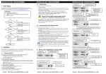
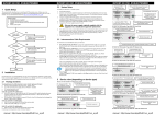
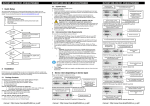
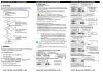
DDXI V1.00 DIGITAL DVI/VGA-KVM-EXTENDER
DDXI V1.00 DIGITAL DVI/VGA-KVM-EXTENDER
2.2
System Setup
Connect to PS/2 keyboard and
mouse using supplied cables
1 Quick Setup
To install your DDXI - DVI KVM Extender system:
This section briefly describes how to install your KVM extender system and optimize the video
signals. Unless you are an experienced user, we recommend that you follow the full procedures
described in the rest of this manual. Refer to the command summary when following this procedure.
1.
2.
4.
Connect Remote unit to KVM.
Connect Local unit to CPU or switch.
Connect Local and Remote units with matching interconnection cable
(CATx, Multimode or Singlemode fiber).
Power up the system.
3.
4.
No
Yes
Connect the interconnect cable to the INTERCONNECT socket(s) as shown below (K4391W), (K437-1W/K438-1W) or (K442-3U/K443-3U).
Connect the 6V power supply to power the unit.
Only use the power supply originally supplied with this
equipment or a manufacturer-approved replacement.
Do you
have a flat screen
(TFT)?
5.
Yes
Carry out the Monitor Setup procedure (please
refer to its manual and see page 40 in this manual).
Programming connector –
for firmware upgrades
DVI-I Connector – DVI/VGA output –
connect to Remote console monitor
Connect to 6V
Power supply
Using the supplied CPU KVM cable(s), connect the keyboard, monitor(s) and mouse
connectors on the computer (or KVM switch) to the corresponding connectors on the Local unit
as shown below (K439-1W), (K437-1W/K438-1W) or (K442-3U/K443-3U).
Ensure that you attach the keyboard and mouse connectors to the correct ports. The keyboard
connector is purple; the mouse connector is green.
INTERCONNECT – carries video
and data signals – connect to
Remote unit
Connect to Local
console keyboard
and mouse
Connect to CPU’s
keyboard and
mouse sockets
If your PC does not have a PS/2 mouse port, an active serial converter will be
required
6.
7.
8.
Do you have a
DVI source?
Switch off all devices.
Connect your keyboard, monitor(s) and mouse to the Remote unit as shown below (K439-1W),
(K437-1W/K438-1W) or (K442-3U/K443-3U).
K437/K438-1W Remote Unit
No
Do you have a
DVI monitor?
INTERCONNECT – carries video and data
signals – connect to Local unit with Fibre cable
These ports may also be attached to the CPU side of a KVM switch in order to
have a Remote CPU. However, if you are attempting to use the extender
between cascaded KVM switches this may not work. Please contact Technical
Support to discuss your application.
Install system
1.
2.
3.
DDXI V1.00 DIGITAL DVI/VGA-KVM-EXTENDER
For a dual access system, connect the keyboard, mouse and monitor for the Local console to the
appropriate ports on the Local unit. The ports may also be used to feed into a KVM switch.
Connect the Interconnection cable from the Remote unit to the INTERCONNECT socket on
the Local unit as shown below (K439-1W), (K437-1W/K438-1W) or (K442-3U/K443-3U).
Power up the system.
Connect 6V
Power supply
Connect to Local
console monitor
Yes
Connect to CPU
video card output
DVI-I Connectors
3 Device View (depending on device type)
Programming
connector – for
firmware upgrades
K437/K438-1W Local Unit
No
Carry out VGA Input Setup procedure
(please follow the instructions on page 42).
Connect to PS/2 keyboard and
mouse using supplied cables
INTERCONNECT – carries video and data
signals – connect to Local unit with CATx cable
4xUSB connectors for
keyboard, mouse and other
devices, for example, printer
Connect 5V
Power supply for
USB high power
INTERCONNECT – carries
video and data signals –
connect to Local unit
Done
2 Installation
For first-time users, we recommend that you carry out a test placement, confined to a single room,
before commencing full installation. This will allow you to identify and solve any cabling problems,
and experiment with the KVM extender system more conveniently.
Programming connector –
for firmware upgrades
DVI-I Connector – DVI/VGA output –
connect to Remote console monitor
Connect to 6V
Power supply
Programming connector –
for firmware upgrades
K439-1W Remote Unit
2.1
Package Contents
You should receive the following items in your extender package (all types) If anything is missing,
please contact Technical Support:
•
Extender Local/Remote unit.
•
2x 6V DC 12W universal power supply for Local/Remote unit.
•
2x DVI-I to VGA adapter (DVI-I dual link male to HD15 female) connector.
•
1x VGA to DVI-I adapter (HD15 male to DVI-I dual link female) connector.
•
Programming cable (DB9 female to RJ11 4p4c).
•
User manual (Quick Setup).
•
2x German-type power cord.
All PS/2 models are supplied with:
•
KVM CPU cable set (1.8m) with PS/2 (6-pin mini-DIN male-to-male) keyboard and mouse
connector and DVI-I video (DVI-I dual link male-to-male) connector
All USB types are supplied with:
•
DVI-I video cable (DVI-I dual link male-to-male)
•
USB cable (USB type A to type B)
•
5V DC 12W universal power supply for Remote unit
(only required when connecting two or more High Power USB
•
US-type power cord (additional)
manual : http://www.ihse.de/pdf/b437-1w_e.pdf
INTERCONNECT – carries video
and data signals – connect to
Remote unit
Connect to 6V
Power supply
Connect to Local
console monitor
Connect to Local
console keyboard
and mouse
Connect to CPU
video card output
DVI-I Connectors
DVI-I Connector – DVI/VGA output –
connect to Remote console monitor
Connect to 6V
Power supply
K439-1W Remote Unit
Connect to CPU’s
keyboard and
mouse sockets
Programming
connector – for
firmware upgrades
K439-1W Local Unit
INTERCONNECT – carries video
and data signals – connect to
Remote unit
Connect 6V
Power supply
Connect to Local
console monitor
USB input – connect to CPU
Connect to CPU
video card output
Programming
connector – for
firmware upgrades
DVI-I Connectors
K442-3U/K443-3U Local Unit
manual : http://www.ihse.de/pdf/b437-1w_e.pdf
manual : http://www.ihse.de/pdf/b437-1w_e.pdf
DDXI V1.00 DIGITAL DVI/VGA-KVM-EXTENDER
3.1
DDXI V1.00 DIGITAL DVI/VGA-KVM-EXTENDER
You can adjust the following properties using the OSD:
Diagnostic LEDs
Each Extender unit is fitted with four indicator LEDs: Communication Error, Link Status, Device
Ready and Video Signal. The Indicator LEDs are located in the same positions on all models in the
DDXI - DVI KVM Extender range. The Communication Error and Link Status LEDs are to the left
and right, respectively, of the Interconnect sockets. The Device Ready and Video Signal LEDs are
next to the Power socket.
As an example, the location of the LEDs is shown below for K439-1W Remote and Local units:
Communication Error
DDXI V1.00 DIGITAL DVI/VGA-KVM-EXTENDER
Link Status
Communication Error
Link Status
Adaptation to analog signal sources (VGA/RGB) – see also manual, page Fehler! Textmarke
nicht definiert..
Color temperature
Brightness/contrast
Saturation
OSD operation, factory reset.
•
•
•
•
•
4.1
Opening the OSD
You can access the OSD in two ways:
Using the keyboard attached to the Remote Unit:
Using our small WINDOWS™ program with a serial connection to the programming port of
the LOCAL UNIT.
While the OSD is active, the mouse is locked and only menu keystrokes are allowed at the keyboard.
To indicate that the OSD mode is active, the status LEDs (Num Lock, Caps Lock and Scroll Lock)
are flashed. There is a summary of OSD commands.
•
•
4.1.1 Using the keyboard attached to the Remote Unit
Video Signal
(Green)
Figure 1
Device Ready
(Red)
Device Ready
(Red)
Video Signal
(Green)
Diagnostic LEDs on Remote (left) and Local (right) units
Type the following key sequence at the Remote console keyboard:
<Ctrl> + <Shift> + < I >
Note. On some keyboards, <Ctrl> is replaced by <Strg>.
DDXi V1.00
DVI/VGAKVM-Extender
To navigate within the OSD:
LED
Appearance
Diagnostics
Communication
Error
Off
Flashing
No communication error for >60 minutes
Indicates number of communication errors during
previous 60 minutes:
slow
medium
fast
10-100 (CATx)
100-1000 (CATx)
>1000 (CATx)
1-2
3-10
>10
(Fiber)
(Fiber)
(Fiber)
Error counter cleared automatically 60 minutes after previous communication error.
Link Status
On
Flashing
Link connection is locked
Interconnection cable not connected or not
functioning
Device Ready
(Red LED)
Off
On
Device not ready
Device ready
Video Signal
(Green LED)
Off
On
No video signal or valid mode detected
Attached and valid mode detected
•
•
•
•
Use the left and right arrow keys to highlight a submenu and/or function.
Press the <ENTER> key to select the highlighted submenu or function.
Select the Exit icon to go back to the previous menu level.
Press the <ESC> key to exit the OSD mode.
4.1.2 Using our WINDOWS™ program attached to the
Local Unit
On all devices, you can use our small WINDOWS™ program, running on a WINDOWS™
computer for OSD access:
•
Download the program from our server
•
•
Connect the programming cable to the programming port of the Local unit.
Connect the programming cable to the serial port of your computer, where the program is
running.
Start the program and follow the on-screen instructions.
Type in the following key: <ENTER>
•
•
When the OSD starts, it displays information about the attached device and firmware version, for
example:
4 Device Control
If you are using the DVI output from your video card and the DVI input to a TFT monitor, no
adjustment should be required. In other cases, when the video signal is converted between analog
and digital formats, either by the Local unit and/or the monitor, you may need to optimize the video
signal using the Extender’s on-screen display (OSD).
Version information
Screen resolution and
refresh rate
Modul Name
Version
Date
Type :
K437-1W
K438-1W
K439-1W
K442-3U
K443-3U
(Quick Setup)
: DVI-KVM-12lo
: Vers.1.3
: 03/05/15
To navigate within the OSD:
•
Use the <L> and <R> keys to highlight a submenu and/or function.
•
Press the <S> key to select the highlighted submenu or function.
•
Select the Exit button to go back to the previous menu level.
Press the <X> key to exit the OSD mode.
Main menu icons
Submenu/command icons
Menu title
Figure 2
OSD Utility
manual : http://www.ihse.de/pdf/b437-1w_e.pdf
manual : http://www.ihse.de/pdf/b437-1w_e.pdf
manual : http://www.ihse.de/pdf/b437-1w_e.pdf