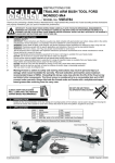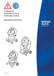
1
INSTRUCTIONS FOR:
INFRARED PARAFFIN/KEROSENE/ DIESEL
HEATER 28/37kW 230V
MODEL No: IR37.V3
Thank you for purchasing a Sealey product. Manufactured to a high standard, this product will, if used according to these instructions,
and properly maintained, give you years of trouble free performance.
IMPORTANT: PLEASE READ THESE INSTRUCTIONS CAREFULLY. NOTE THE SAFE OPERATIONAL REQUIREMENTS, WARNINGS & CAUTIONS. USE THE PRODUCT
CORRECTLY AND WITH CARE FOR THE PURPOSE FOR WHICH IT IS INTENDED. FAILURE TO DO SO MAY CAUSE DAMAGE AND/OR PERSONAL INJURY AND WILL
INVALIDATE THE WARRANTY. KEEP THESE INSTRUCTIONS SAFE FOR FUTURE USE.
Read instruction Wear protective
manual
gloves (refuelling)
1.1.
ELECTRICAL SAFETY
WARNING! It is the responsibility of the owner and the operator to read, understand and comply with the following:
You must check all electrical products, before use, to ensure that they are safe. You must inspect power cables, plugs, sockets and any other connectors for wear or damage. You must ensure that the risk of electric shock is minimised by the installation of appropriate safety devices. A Residual Current Circuit Breaker (RCCB) should be incorporated in the main distribution board. We also recommend that a Residual Current Device (RCD) is used. It is particularly important to use an RCD with portable products that are plugged into a supply which is not protected by an RCCB. If in any doubt consult a qualified electrician. You may obtain a Residual Current Device by contacting your Sealey dealer.
You must also read and understand the following instructions concerning electrical safety.
1.1.1. The Electricity at Work Act 1989 requires that all portable electrical appliances, if used on business premises, are tested by a qualified electrician, using a Portable Appliance Tester (PAT), at least once a year.
1.1.2. The Health & Safety at Work Act 1974 makes owners of electrical appliances responsible for the safe condition of those appliances and the safety of the appliance operators. If in any doubt about electrical safety, contact a qualified electrician.
1.1.3. Ensure that the insulation on all cables and on the appliance is safe before connecting it to the power supply. See 1.1.1. and 1.1.2. and use a Portable Appliance Tester.
1.1.4. Ensure that cables are always protected against short circuit and overload.
1.1.5. Regularly inspect power supply cables and plugs for wear or damage and check all connections to ensure that none is loose.
1.1.6. Important: Ensure that the voltage marked on the appliance matches the power supply to be used and that the plug is fitted with the correct fuse - see fuse rating at right.
1.1.7. DO NOT pull or carry the appliance by the power cable.
1.1.8. DO NOT pull the plug from the socket by the cable.
1.1.9. DO NOT use worn or damaged cables, plugs or connectors. Immediately have any faulty item repaired or replaced by a qualified electrician. When a BS 1363/A UK 3 pin plug is damaged,cut the cable just above the plug and dispose of the plug safely.
Fit a new plug according to the following instructions (UK only).
RECOMMENDED
a)Connect the GREEN/YELLOW earth wire to the earth terminal ‘E’.
FUSE RATING: 5AMP
b)Connect the BROWN live wire to the live terminal ‘L’.
c)Connect the BLUE neutral wire to the neutral terminal ‘N’.
d)After wiring, check that there are no bare wires, that all wires have been correctly connected, that the cable outer insulation extends beyond the cable restraint and that the restraint is tight.
Double insulated products, which are always marked with this symbol , are fitted with live (brown) and neutral (blue) wires only. To rewire, connect the wires as indicated above.
DO NOT connect either wire to the earth terminal.
1.1.10. Products which require more than 13 amps are supplied without a plug. In this case you must contact a qualified electrician to ensure that a suitably rated supply is available. We recommend that you discuss the installation of an industrial round pin plug and socket with your electrician.
1.1.11. If an extension reel is used it should be fully unwound before connection. A reel with an RCD fitted is preferred since any appliance plugged into it will be protected. The cable core section is important and should be at least 1.5mm², but to be absolutely sure that the capacity of the reel is suitable for this product and for others which may be used in the other output sockets, we recommend the use of 2.5mm² section cable.
1.2.
GENERAL SAFETY
DANGER! Risk of carbon monoxide poisoning. Failure to provide proper ventilation could result in serious illness or death.
Check that the heater is in sound condition and good working order. Take immediate action to repair or replace damaged parts.
Use recommended parts only. Unauthorised parts may be dangerous and will invalidate the warranty.
Only use paraffin, diesel or kerosene to fuel this heater, in accordance with instructions contained in this manual.
Locate heater on a level and stable surface.
WARNING! Only use heater in well ventilated areas. Ensure continuous ventilation is provided to the heater operating area via windows and doors etc. If people are not required to be present in the heated area, the volume of air to be heated (mtr³)/heat output (kW) ratio must be at least 10:1 and people must be advised not to remain in the heated area for prolonged periods. If people are required to be present in the heated area, the volume of air to be heated (mtr³)/heat output (kW) ratio must be at least 30:1. Ventilation must be to the outside of the premises in which the heater is to be operated. The total open area (mtr²) must be at least 0.003 times the total heat output (kW). The volume concentration of oxygen (O ) in the heated room, must always remain above 17%.
²
WARNING! DO NOT use the heater near flammable material, liquids, solids, gases or compressed gas cylinders etc.
DO NOT stand or place any object less than 3m from the heater output and keep the heater a minimum of 2m from any walls or objects.
DO NOT use the heater in closed rooms, living areas, basements or below ground level.
DO NOT allow untrained persons to operate the heater and DO NOT operate the heater without the safety guard.
DO NOT move or handle the heater when hot, without wearing protective gloves. Never move the heater whilst it is operating.
CONTINUED OVERLEAF
© Jack Sealey Limited
Original Language Version
IR37.V3
Issue:4(I) - 18/02/15
DO NOT leave the heater unattended for prolonged periods of time when in use. Switch the heater off and unplug from the mains before leaving work area.
DO NOT fill the fuel tank whilst the heater is running or still hot. DO NOT over-fill the fuel container. Wipe up any spilt fuel immediately.
DO NOT obstruct the air inlet (rear) and air outlet (front) of the heater and DO NOT use duct work in front or at the rear of the heater.
DO NOT allow children or animals near the heater when in use, or whilst still hot.
WARNING! RISK OF ELECTRIC SHOCK. DO NOT expose the heater to water spray, rain, dripping water or wind.
DO NOT operate the heater when you are tired or under the influence of alcohol, drugs or intoxicating medication.
DO NOT touch the heater outlet or cone when in use, or for a period of time after it’s switched off, as these are VERY hot and will take time to cool down.
DO NOT switch the heater off by disconnecting it from the mains. ALWAYS set the switch on the burner to the ‘OFF’ position and allow the cooling cycle to finish, before disconnecting from the mains.
DO NOT use an external fuel tank. Only use the tank that is fitted to the heater, and only fill it when the heater has cooled down.
Ensure that the heater is correctly turned off
When not in use for an extended period, store in a safe, dry area, out of reach of children.
Important: This appliance is not intended for persons (including children) with reduced physical, sensory or mental capabilities, or lack of experience and knowledge, unless they have been given supervision or instruction concerning use of the appliance by a person responsible for their safety. Children should be supervised to ensure that they do not play with the appliance.
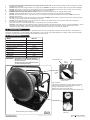
2. INTRODUCTION
Infrared heater suitable for well ventilated indoor applications. Clean burning unit operates on paraffin, kerosene or diesel. Unit produces an
impressive 125,000 Btu/hr on highest setting. 53ltr tank allows a max. of 20 hrs running time dependant on setting, making this unit extremely
economical. Complies with rigorous standards and is fitted with a safety cut-out.
3. SPECIFICATION
Model
IR37.V3
Heat Output
28 / 37 kW
Rating
95,000 / 125,000 BTU/hr
Fuel
Paraffin / Kerosene / Diesel
Running Time Per Filling (Max)
Fuel Tank Capacity
20 hrs
53 Litres
Heated Area
25000ft³ / 708m³
Voltage / Hz
230V / 50Hz
Rated Amps
5A
Net Weight
33 Kg
WARNING! This heater is not suitable for use with
Bio-Diesel; use of Bio-Diesel will damage the filter and seals.
Damage caused by use of Bio-Diesel will not be covered by warranty.
Green (Power on)
Flashing Red (Misfire)
Low
Setting
High
Setting
Power
Off.
3 Position Switch on
Control Panel
Tips on ignition:The photocell is sensitive to sunlight, ignite in the shade.
Listen for fan followed by pump, after switch position " "
Priming essential when new, see 5.5.4.
Observe the fuel level in the filter bowl.
Clean fuel requires clean reservoir and clean transfer cans.
Heater Module (under carriage removed)
© Jack Sealey Limited
Fig.1
Original Language Version
Fuel Gauge and
Filler Cap
IR37.V3
Issue:4(I) - 18/02/15
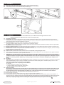
4. ASSEMBLY
4.1. Slide axle through Wheel Frame and attach wheels, washers and cotter pins (Fig.2).
4.2. Place main structure on Wheel Frame and fasten with nuts and bolts provided (Fig.3).
4.3. Attach Safety Guard to front of heater with bolts provided (Fig.4).
Fig.3
Fig.2
Fig.4
5. OPERATION
WARNING! This heater is not suitable for use with Bio-Diesel; use of Bio-Diesel will damage the filter and seals.
Damage caused by use of Bio-Diesel will not be covered by warranty.
5.1. Principles of Operation
5.1.1.Fuel System: This heater is equipped with an air pump that operates off the electric motor. The pump forces air through the air line
connected to the fuel tank, drawing fuel to the nozzle in the burner head. Air also passes through the nozzle where it mixes with the fuel and is sprayed into the combustion chamber as a fine mist.
5.1.2.Quick-Fire Ignition: A transformer sends high voltage to a two pronged spark plug.
The spark ignites the fuel/air mixture as it is sprayed into the combustion chamber.
5.1.3.Air System: A fan is turned by the heavy duty motor, which forces air around and into the combustion chamber, where it is super-heated and forced out the front of the chamber.
5.1.4.Electrical System Protection: The heater’s electrical system is protected by a circuit breaker that protects the system components from damage. If the heater fails, check the fuse first, and replace if necessary.
5.1.5.Flame Sensor: The heater uses a photocell to see the flame in the combustion chamber. Should the flame extinguish, the sensor will stop
electrical current and the heater will shut off.
5.1.6.Tip-over Sensor: The heater uses a tip-over sensor.
5.2. Fuel: the heater operates with paraffin, kerosene or diesel fuel. DO NOT use any other type of fuel.
5.3. When used in the construction or agricultural industries ensure that the safety regulations in force are adhered to with regard to distances from flammable materials and any other specified substances.
WARNING! Air contaminants taken into the heater may affect the heat output, damage the unit and may cause health problems.
Example: Bodyshop filler dust/paint overspray will damage the motor bearing, clog the filter and compressor and contaminate the combustion chamber causing flame flutter and health hazards. Please note that any parts damaged by filler dust/paint overspray will not be covered by warranty. Additionally, a cleaning charge will be made for any heaters damaged by filler dust/paint over
spray.
5.4.Ventilation:
WARNING! Only use the heater in well ventilated areas. Careful consideration must be given to the placing of the heater to provide safe and comfortable heating. Ensure continuous ventilation is provided to the heater operating area. A ventilation opening must run to the
outside of the premises in which the heater is to be operated.
The heater requires a fresh air opening of at least 2800cm².
For Example:
- A two car garage door should be open at least 11cm.
- A single car garage door should be open at least 16cm.
- Two 76cm windows should be open at least 20cm.
5.5. Starting the Heater.
NOTE: If air has entered the fuel line; possible when new, when left standing for a long period or when the tank level has fallen too low, priming may be necessary (see 5.5.4). It is preferable to start the heater outdoors for the first time, to allow any oils left over from the manufacturing process and transporting to be burnt off in a safe environment. Run it for 10 minutes on this first burn.
5.5.1.Carefully fill the fuel tank with clean approved fuel until fuel gauge (Fig.1) points to 'F'.
5.5.2.Ensure the fuel cap is secure.
5.5.3.Plug the power cord into a suitable power socket. If using an extension lead see Section 1.1.11.
5.5.4.Turn the power knob in Fig.1 from "O" to the " " setting. The green "power indicator" lamp will illuminate, the fan will run followed in 15 seconds by the pump. Inside the next 30 seconds the heater will ignite. If the heater does not ignite the red "Misfire" lamp will illuminate and flash. Switch the unit off "O" and wait approximately 20 seconds before attempting to ignite again; this 20 seconds will allow the PCB to recalibrate. Allow for up to 5 ignition (priming) cycles. On successful ignition, if required, increase the heat by turning the knob to setting " ".
© Jack Sealey Limited
Original Language Version
IR37.V3
Issue:4(I) - 18/02/15
5.5.5. When switching from one heat level to another during operation, it may cease operating and go into the misfire sequence. If this happens, turn the power knob to the "O" position and immediately turn it to the desired heat level.
Note: The electrical components of this heater are protected by a fuse mounted in the PCB. If the heater fails to fire, check this fuse first, and replace if necessary. Also check the power source to ensure that the correct voltage is being provided to the heater.
5.6. Tilting Feature.
5.6.1.Loosen the hand screws on the main frame of the heater, position the heater in the desired position, and tighten the hand screws to secure the heater in the tilted position.
5.7. To Stop the Heater.
5.7.1.Turn the power knob to the "O" position. Combustion will stop, and the Cooling Cycle (approx. 5 minutes in duration) will begin.
5.7.2.When the Cooling Cycle is completed (fan stops running), it is safe to unplug the heater.
WARNING! Unplugging the heater before the Cooling Cycle has finished may cause overheating, possible damage to the heater and heat plate, and will invalidate the warranty.
5.8. To Restart the Heater.
5.8.1.Wait ten seconds after the cooling cycle has completed.
5.8.2.Turn the power knob to the position and wait 10 seconds before adjusting heat level if required.
5.8.3.Be sure to follow all starting procedure precautions.
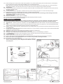
6. MAINTENANCE
Use only original equipment replacement parts. Isolate power before any maintenance. The use of alternate or third party components
can cause unsafe operating conditions, and will invalidate the warranty. We suggest following a maintenance schedule as follows.
6.1. Fuel/Fuel Tank - Flush every 200 hours of operation or as needed. DO NOT use water to flush the tank. Use fresh kerosene/paraffin/diesel only.
6.2. Filters - The Fuel Filter and Oil Filter should be cleaned at least twice per heating season by rinsing them in clean kerosene/paraffin/diesel. This procedure should also be followed if the fuel is found to be contaminated (Fig.5).
6.3. Nozzle - Nozzles should be cleaned or replaced at least once per heating season. This procedure should also be followed if the fuel is found to be contaminated.
6.3.1.To clean dirt from nozzle, blow compressed air through nozzle front. It may be necessary to soak the nozzle in clean kerosene/paraffin/diesel to help loosen any particles (Fig.6).
6.4. Spark Plug - Clean and re-gap every 600 hours of operation, or replace as needed (Fig.7).
6.4.1.After removing the Spark Plug, clean the terminals with a wire brush.
6.5.Photocell - The Photocell should be cleaned at least once per heating season or more depending on conditions.
6.5.1.
Isolate power before using a cotton swab dipped in water or alcohol to clean the lens of the Photocell (Figs.8 and 9).
6.6. Long Term Storage.
6.6.1.Unscrew the Drain Bolt and drain fuel into a suitable container (Fig.10).
6.6.2.Using a small amount of kerosene/paraffin/diesel, rinse and swirl the fuel around the fuel tank. Empty the tank completely.
6.6.3.Never store leftover kerosene/paraffin/diesel over the summer. Using old fuel can damage the heater.
6.6.4.Store heater in a dry, well ventilated area.
6.6.5.Be sure that the storage area is free of dust and corrosive vapours. Repack the heater in the original shipping material. Keep this User’s Manual in an easily
Fig.6
accessible place.
Fig.7
Fig.5
Fig.8
Fig.9
Fig.10
© Jack Sealey Limited
Original Language Version
IR37.V3
Issue:4(I) - 18/02/15
7. TROUBLESHOOTING
Although this heater operates with
diesel fuel, when the temperatures
are below 0°C, diesel additives are
required to maintain the diesel's
viscosity. Typically diesel can cloud
in freezing conditions and will start to
gel. You will need additives for your
fuel in these conditions.
Kerosene/Paraffin does not start to
gel until the ambient temperature is
around -40°C.
1. Dirty Fuel Filter.
1. Clean/replace Fuel Filter.
2. Nozzle Dirty.
2. Clean/replace Nozzle.
3. Photocell Dirty.
3. Clean/replace Photocell.
4. Photocell not installed properly.
4. Adjust Photocell position.
5. Photocell Defective.
5. Replace Photocell.
6. Improper electrical connection between Circuit
Board and Photocell.
6. Check wiring connections
(See Wiring Diagram, Fig.10).
7. Cooling Fan is obstructed.
7. Check to make sure cooling fan is not obstructed.
1. No fuel in fuel tank.
1. Fill tank with fresh fuel.
2. Corroded Spark Plug or incorrect plug gap.
2. Clean/replace Spark Plug.
3. Dirty Fuel Filter.
3. Clean/replace Fuel Filter.
4. Dirty Nozzle.
4. Clean/replace Nozzle.
5. Moisture in Fuel/Fuel Tank.
5. Rinse out fuel tank and fill with clean fresh fuel.
6. Improper electrical connection between
Transformer and Circuit Board.
6. Inspect all electrical connections.
(see Wiring Diagram, Fig.10).
7. Transformer Wires not connected to Spark Plug.
7. Re-attach Transformer wires to Spark Plug.
8. Defective Transformer.
8. Replace Transformer.
Fan does not operate when heater
is plugged in and Power Switch is
in the " "/" "
1. Broken electrical connection between Circuit Board
and motor.
1. Inspect all electrical connections.
(see Wiring Diagram, Fig.10).
2. Not enough amps available to power heater.
2. Use a new extension cord or try another
electrical socket.
Heater does not turn on and the
lamp is not lit.
1. Temperature limit sensor has overheated.
1. Turn Power Knob to "O" and allow heater to cool
for 5 minutes. Turn Power Knob back to (" ").
2. No electrical power.
2. Check power cord and extension cord to ensure
proper connection. Test power supply.
3. Fuse break down.
3. Check/replace Fuse.
4. Improper electrical connection between
Temperature Limit Sensor and Circuit Board.
4. Inspect all electrical connections.
(See Wiring Diagram, Fig.10).
1. Incorrect pump pressure.
1. Ensure pump pressure is adjusted correctly.
2. Poor fuel quality.
2. Ensure fuel is not old or contaminated.
Heater will not operate, or motor
runs for short time.
Poor combustion and / or soot
production.
Solution
Possible Cause
Problem
Heater fires, but shuts down after a
short period of time.
Environmental Protection
Recycle unwanted materials instead of disposing of them
as waste. All tools, accessories and packaging should be
sorted, taken to a recycling centre and disposed of in a
manner which is compatible with the environment.
When the product becomes completely unserviceable and
requires disposal, drain off any fluids into approved
containers and dispose of the product and the fluids
according to local regulations.
WEEE Regulations
Dispose of this product at the end of its working life
in compliance with the EU Directive on Waste
Electrical and Electronic Equipment (WEEE). When
the product is no longer required, it must be
disposed of in an environmentally protective way.
Contact your local solid waste authority for recycling
information.
NOTE: It is our policy to continually improve products and as such we reserve the right to alter data, specifications and component parts without prior notice.
IMPORTANT: No liability is accepted for incorrect use of this product.
WARRANTY: Guarantee is 12 months from purchase date, proof of which will be required for any claim.
Sole UK Distributor, Sealey Group,
Kempson Way, Suffolk Business Park,
Bury St. Edmunds, Suffolk,
IP32 7AR
© Jack Sealey Limited
Original Language Version
01284 757500
www.sealey.co.uk
01284 703534
[email protected]
IR37.V3
Issue:4(I) - 18/02/15