1
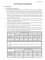
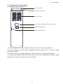
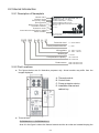
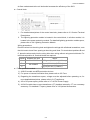
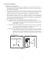
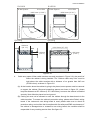
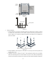
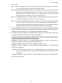
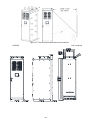
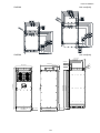
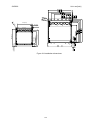
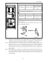
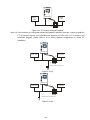
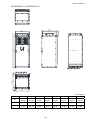
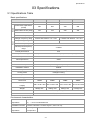
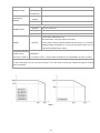
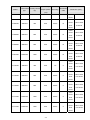
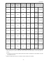
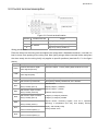
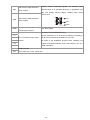
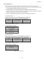
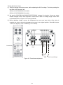
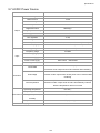
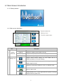
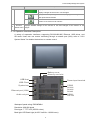
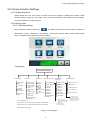
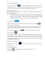
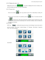
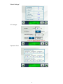
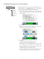
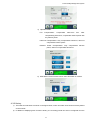
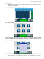
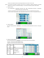
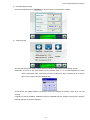
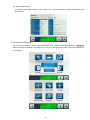
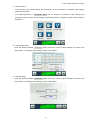
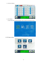
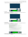
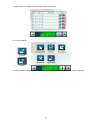
6* Before You Start Please carefully read and be aware of the relevant safety information before operating this product for your and the product's safety. ; Please make sure that the power is off before configuring wires or installing the DANGER Static VAR Generator (SVG). ; Wait at least 10 minutes after turning off the AC power, as high voltage still exists inside the Static VAR Generator (SVG) and is extremely dangerous. Please make sure that the DC voltage drops to 0V before configuring wires or installation. ; The IC components on the Static VAR Generator's internal circuit board are susceptible to damage from electrostatic discharge. Please do not touch the circuit board with bare hands. Unauthorized alteration of components or circuits within the Static VAR Generator (SVG) should be avoided. ; The Static VAR Generator (SVG) and its components should not be installed near heat sources and flammable objects. ; If working under humid or live wire conditions is unavoidable, please stand on dry rubber mats or wooden boards and wear insulated gloves. ; All models come packaged with a User Manual and 2 keys. Please keep them safe CAU TION as we are unable to provide replacements if the keys are lost or stolen. If you need help unlocking the device, please ask for assistance at a local dealer, or contact Delta's Industrial Automation Business Unit. ; Read and follow all instructions in this User Manual before installing, operating, or servicing the product. Please keep the User Manual, do not discard as it will be needed for further use. ; Before installation or maintenance, wear appropriate safety clothing, follow safety operating procedures, and use proper testing equipment as electric spark may damage the eyes, burn skin, damage equipment, or ignite combustibles. ; Only specialists from the manufacturer or authorized dealers may perform maintenance on the Static VAR Generator (SVG). Installation, wiring, and maintenance of the Static VAR Generator (SVG) may only be performed after the content of this manual is clearly understood. ; Have certified electrical professionals confirm that the Static VAR Generator (SVG) has been properly grounded to prevent injuries caused by leakage current. ; Even if the Static VAR Generator (SVG) is currently inactive, the main circuit terminals of the Static VAR Generator (SVG) can still carry dangerous voltage. ; If unpacked and used for over 3 months, the ambient temperature of the storage environment must not exceed 30°C as the capabilities of the electrolytic capacitors deteriorate easily when stored at a high ambient temperature without power. Please I do not leave the device powered off for a period longer than 1 year. ; Notes for the disinfection and disinfestation of packaging materials for transportation and installation (including wooden crates, planks, cardboard boxes, etc.): 1. When disinfecting or disinfesting packaging materials, such as crates or cartons, please do not fumigate to avoid damaging internal components. 2. Please use alternative environmental disinfection or disinfestation methods. 3. High-temperature usage: Let the packaging sit for at least 30 minutes in temperature above 56°C. 4. Fumigation should be avoided. Any damage caused by fumigation will not be covered by the warranty. NOTE The pictures and corresponding descriptions in this manual will feature the product with the outer casing or safety shields removed or disassembled to better explain the product in detail.As for the actual product in operation, please be sure to correctly install the outer casing and wirings in accordance with the rules and regulations, and operate the product following the instructions in the manual to ensure your safety. The illustrations in the manual may slightly differ from the actual product for demonstration purposes, but will not affect the rights and interests of the customer. When product documentation is updated or modified, the latest edition can be downloaded from the industrial automation product page on the Delta Electronics website. II Installation Checklist The following table provides installation details so as to enable quick and convenient assembly by to a professional electrical engineer. These steps can prevent human errors that cause unnecessary harm. NOTE Only qualified electrical engineers should adjust the equipment. Carefully read and follow the manual's Before You Start safety instructions. Ignoring the safety instructions can cause injury or death. Installation of Equipment □ Is the equipment being installed in a well ventilated, indoor area with a relative humidity of less than 90% without condensation? □ Is the operating environment temperature maintained at -10~45°C (SVG300AXXA-XX model); -10~40°C (SVG500AXXA-XX model)? □ Installation Complies with Degrees of Pollution: Degree 2 (for a factory environment) and contamination-free substances without e-waste contaminated dust particles. □ The location of the equipment must be approved for fire safety, must be clean, must not be within the vicinity of corrosive gases, and must not vibrate. □ Is there any weight or items stacked on top of the Static VAR Generator? □ Is it placed on level ground? Electrical Installation □ The equipment is grounded □ The equipment's input voltage value is consistent with the supply voltage □ Is the wiring for the input terminals correct? □ Has the power cable been properly chosen? Refer to the User Manual. □ The input terminal must be connected to the fuse and isolation switch. Refer to the User Manual. □ Does the voltage value of the equipment's transformer match the voltage supply? □ Is the orientation of the CT installation correct? "Current transformer grid terminal: K (S1); Load terminal: L (S2)" □ Is the installation of the CT diameter and length correct? Please refer to the User Manual. □ Confirm that there are no other conductors and assembly parts inside the Static VAR Generator (SVG). □ Confirm that the cover is back in place after adjusting the voltage of the transformer. Before Starting the Device □ Before starting the Static VAR Generator (SVG), determine whether the I/O of the power supply relay is in an uncharged state. □ When the power cable wiring is complete, check that the cabinet door is closed. □ When the power cable wiring is complete, to ensure safety, do not touch the cable. □ If the cable is exposed, please provide clear warning signs such as "Do Not Touch the Cable". III Turning On the Power Voltage □ Turn on the main breaker of the power transformer □ Turn on the device's circuit breaker/isolation switch and the transformer's circuit breaker □ After the power is on, check whether the fan is operating normally □ After the power is on, check whether the vent is blocked □ After the power is on, check whether the display of the power quality control system is normal □ After the power is on, check whether the touch screen of the power quality control system is normal IV Table of Contents 01 Product Overview ………………………………………………………………………………...1-1 1-1 Usage….……………………………………………………………………………………..…………1-1 1-2 Storage…….……………………………………………………………………………………..…..…1-1 1-3 Transportation…….………………………………………………………………………………….…1-2 02 Product Installation…………………………………….………………………………….…..…2-1 2-1 Installation……………………………………………………………………………….………………2-1 2-1-1 Installation Precautions…………………………………………..………………………………2-1 2-1-2 Description of Appearance…………………………………………………………………….…2-2 2-2 Internal Introduction……………………………………………………………………………...…….2-4 2-2-1 Description of Nameplate………………………………………………………….………..……2-4 2-2-2 Part Locations……………………………………………………………………………….….…2-4 2-3 Cabinet Installation……………………………………………………………………………….….…2-6 2-4 Wiring Installation……………………………………………………………………...……….….…2-11 2-4-1 Wiring………………………………………………………………………………………..……2-15 2-5 Exterior Dimensions…………………………………………….……………………………….……2-16 03 Specifications ………………………………...………………….……..…………………..…….3-1 3-1 Specifications Table……………………………………………………………………………………3-1 3-2 Optional Accessories……………………………………………………………….……………….…3-1 3-2-1 Current Transformer………………………………………………………….………………..…3-1 3-3 Control Terminal Descriptions……………………………………………………….………...…..…3-1 3-4 Lightning Protection Module………………………………………………………….…………….…3-1 3-5 Fans…………………………………………………………………………….…………....…….....…3-1 3-6 Transformer………………………………………………………………………….………….…...…3-1 3-7 AC/DC Power Source………………………………………………………………….………..….…3-1 04 Power Quality Management System…...………………………………………...………..…..4-1 05 Maintenance………………………………………………………………………………….….…5-1 V Product Overview 01 Product Overview 1-1 Usage The Static VAR Generator is used to compensate harmonics depending on the harmonic and the Static VAR Generator's compensation capacity so that compensation will not be affected due to insufficient capacity. An external harmonic current detection CT needs to be installed for the Static VAR Generator to perform harmonic treatment. To ensure the Static VAR Generator performs with maximum efficiency, please install the device in a well ventilated environment and do not block or cover the air vents. Refer to Figure 2-1a/ 2-1b. Please maintain the Static VAR Generator's operating ambient temperature at -10~45°C (SVG300AXXA-XX model); -10~40°C (SVG500AXXA-XX model). Abnormal operation could occur if the temperature exceeds this range. Upon receiving the product, please first examine the carton for any signs of abnormal damage during shipping. In such cases, please contact our local dealer or Delta sales immediately to help with relevant matters. Once you confirm that the Static VAR Generator's carton has no signs of abnormal damage, remove the manual located on the carton and have a professional technician install the Static VAR Generator according to the instructions. After removing the carton, please check and make sure the product nameplate matches the product model you purchased. Refer to 2-2-1 Description of Nameplate. Please keep the operating environment dust-free. Do not allow any fiber, paper scraps, sawdust, metal scraps or other foreign objects to enter the Static VAR Generator or attach to the cooling fans, as this will cause the Static VAR Generator to operate abnormally. When wiring the Current Transformer, please note the wiring positions for the input terminals "K1, K2, K3" and the output terminals "L1, L2, L3". Please do not connect the wires to the wrong terminals because the machine will not work. This product complies with the following safety and EMC standards International Standards Chinese National Standards IEEE519-1992 GB/T14549-93 (Quality of electric energy supply - IEC/EN61000-3-12 Harmonics in public supply networks) IEC/EN61000-3-4 SD 126-84 Provisional regulations on IEC/EN61000-3-2 management of power system harmonics IEC/EN61000-2-2 Regulations on the administration of electric IEC/EN61000-3-3 power dispatch to networks and grids IEC/EN61000-2-4 TOR D2 G5/4 D-A-CH-CZ 1-1 1-2 Storage If immediate installation is not needed, store the Static VAR Generator in a well ventilated area indoors with relative humidity <90% without condensation. The Static VAR Generator should be installed according to the degree of pollution: Degree 2 (for a factory environment) and clean circulating air. Clean circulating air is defined as air without contaminated substances or e-waste contaminated dust particles. This product is designed to maximize reliability. If installed and used correctly, this product should provide a lasting, hassle-free service life. Visual inspections should be conducted at least every 6 months to ensure the cables are fastened and to avoid the accumulation of dust, dirt, or other unrelated particles, as these will affect heat dissipation. The storage location must be qualified for fire safety, be dust-free, without corrosive gases in the surrounding area, and without vibration. Please do no stack heavy objects on top of the Static VAR Generator. Please do not place the Static VAR Generator on a slope or uneven ground to avoid damage the Static VAR Generator. Please do not let any fiber, paper scraps, sawdust, metal scraps or other foreign objects enter the Static VAR Generator or attach to the cooling fans. The iron grate at the Static VAR Generator's air inlet can get clogged by foreign objects. Please clean the iron mesh manually on a regular basis. Before cleaning the iron grate, the Static VAR Generator must first be turned off to ensure personal safety. Proper protective equipment such as insulating gloves or protective goggles must be worn before performing maintenance. 1-3 Transportation All models are floor-standing cabinets. When transporting and installing the Static VAR Generator, do not lay it flat, tilt it, or lift a side to avoid damaging the Static VAR Generator. When moving, do not tilt, lie flat, or lift by one side. The Static VAR Generator must be transported upright. Please be sure to adhere to the aforementioned guidelines to prevent the models from being damaged due to improper transportation. 1-2 Product Overview Unpacking Description Floor Cabinet Models (SVG300A43A-11 is shown in the figure below as an example) 1) With a flat-head screwdriver, pry open all 10 fasteners on both sides of the carton. (As shown in the figure below) 2) Remove the carton and 4 EPE from both sides. Note that the front of the cabinet is facing the lid of the carton (the direction as indicated by the elongated arrow) (see Figure 1-5 below). Open the outer lid of the model by the handle, and you will find the user manual and the keys for the outer lid attached to the inner side of the outer lid (see Figure 1-6 below). Please keep the keys safe as only 2 keys are included in each model. The keys cannot be replaced if lost. Figure 1-5 Figure 1-6 1-3 3) As shown in Figure 1-7(a) below, remove the 12 base-fixing M5 screws. As shown in Figure 1-7(b) below, remove the 8 base-fixing M5 screws. 4) With hoist rings [see Figure 1-8(a)(b) below], lift the Static VAR Generator and place into the designated position. (For more details on hoist ring devices please refer to 1-3-3 Hoist Ring Installation) Figure 1-8(a): Static VAR Generator + L-shaped iron plate Figure 1-8(b): Static VAR Generator 5) For detailed methods on installing floor cabinet models, please refer to 2-3 Cabinet Installation. Figure 1-7(a) Figure 1-7(b) Figure 1-8(a) Figure 1-8(b) 1-4 Product Overview Hoist Ring Installation SVG300AXXA-11/SVG500AXXA-11 Set up the lifting hole position Note how hoist rings are installed. Please avoid inappropriate installation that will cause the SVG lifting holes to deform. SVG300AXXX-XX Model Weight: 650 kg (1,433 lbs) ± 10% (margin of error) SVG500AXXX-XX Model Weight: 1,100 kg (2,425 lbs) ± 10% (margin of error) Please be aware of the lifting angle between the SVG lifting holes and the lifting hook. (For the purpose of the base-fixing iron plate, please refer to 2-3 Cabinet Installation) With base-fixing iron plate 1-5 Without fixing iron plate Product Installation 02 Product Installation 2-1 Installation 2-1-1Installation precautions Before installing the Static VAR Generator (SVG) cabinet, please make sure the Static VAR Generator's (SVG) input terminal system power is turned off to keep the wiring technician safe. When configuring wires for the power input terminal of the Static VAR Generator (SVG), please be aware of the position and status of the switches connecting the Static VAR Generator (SVG) and mains wirings. Wait at least 10 minutes after turning off the Static VAR Generator (SVG) until DC voltage of the Static VAR Generator (SVG) drops to 0V before disassembling to ensure the safety of installation personnel. Please read carefully and follow the installation procedures, and take precautions during installation. Study local electrical code, and make sure the input power matches the rated voltage of the equipment being installed. Check that the wirings are connected correctly on the power supply end and the control parts, and tighten the wiring screws. Refer to 2-4 Wiring Installation. It is strictly prohibited to lay flat, tilt, lift one side of the Static VAR Generator (SVG) when installing to avoid damaging the Static VAR Generator (SVG). When installing the current transformer, please note that the grid end of the current transformer should be connected to K (S1), and the load end to L (S2). For more details on the installation of the current transformer, please refer to 3-2 Optional Accessories. Air flow rate for cooling Model No. ※ 3 Flow Rate (cfm) Flow Rate (m /hr) External Internal Total External Internal Total SVG300A43A-11 631 411 1042 1073 699 1772 SVG300A63A-11 1235 411 1646 2098 699 2797 SVG500A43A-11 1236 521 1756 2100 885 2985 SVG500A63A-11 1236 521 1756 2100 885 2985 The table shows the required air flow rate for each model when installing single units in a closed space. ※ For multiple units, multiply the required air flow rate for single-unit installation by the number of units installed. SVG Power Dissipation Model No. Power Dissipation (watt) Loss External(Heat sink) Internal Total SVG300A43A-11 4857 2948 7806 SVG300A63A-11 7743 3292 11035 SVG500A43A-11 7891 6694 14585 SVG500A63A-11 10506 5662 16168 2-1 SVG Power Dissipation ※ The table shows the required heat dissipation rate due to heat loss for each model when installing single units in a closed space. ※ For multiple units, multiply the heat dissipation rate for single units by the number of units installed. ※ The heat dissipation data are calculated based on each model operating under rated voltage, current, and default carrier wave. 2-2 Product Installation 2-1-2 Appearance descriptions SVG300AXXA-XX/SVG500AXXA-XX Air flow outlet Install hoist r ing* a Air flow inlet Power Quality M anagement System* b Model nameplate* c Cabinet keykole* d *a For more details on hoist ring installation, please refer to 1-3-3 Hoist ring installation *b For more details on power quality management system, please refer to 04 Power Quality Management System *c For more details on nameplate descriptions, please refer to 2-2-1 Nameplate descriptions *d Two keys are attached inside the cabinet, which can be used to open/lock the cabinet. Please keep the keys in a secure location and do not lose them. 2-3 2-2 Internal Introduction 2-2-1 Description of Nameplate Model name Voltage range Frequency range Wiring phase Rated offset capacity Firmware version Protection level International certification labels Serial number MODEL:SVG300A43A-11 POWER VOLTAGE : 200- 480V POWER FREQUENCY : 5 0/6 0HZ PHASE CONNECTION:3PH+PE RATED COMPENSATION CAPACITY:XXX KVAR Ver sion : 1 .0 IP2 1 /NEMA 1 DELTA ELECTRONICS, I NC. MADE I N XXXXXXX XXXXXXXXXXXXXXXX Protection level 11: IP21& NEMA1 SVG 300 A 43 A - 11 Power protection device Wiring phase Model type Compensation Capacity Product name A: NFB 43 : 460V 3- Phase 63 : 690V 3- Phase A Ser ies 300: 300kVAR 500: 500kVAR Static VAR Gener ator Static VAR Gener ator 2-2-2 Part Locations ; The figures below are for illustrative purposes only. Actual models may differ from the images displayed. A: B: C: D: ; Thermal module Control block Power protection device Installation Manual and cabinet key Thermal block SVG300AXXA-11/ SVG500AXXA-11 Area A in the figure is where the thermal module and the air outlet are located.Keeping the 2-4 Product Installation air flow unobstructed at the air inlet/outlet increases the efficiency of the SVG ; Control block RS-485 port*2 1. For detailed descriptions of the control terminals, please refer to 3-3 Control Terminal Descriptions. 2. The lightning protection module is located in the control block; in all other models, it is located in the power protection module. For detailed lightning protection module specs, please refer to 3-4 Lightning Protection Module. Wiring precautions: Place the wires into the wiring hole and tighten the wirings with a flathead screwdriver, note that it is best to leave 5mm spacing at the wiring end. Note: For terminals at positions B and C, place the wires neatly into the wiring hole when wiring without using terminal blocks. For terminals at position A, terminal blocks are required. Position Suitable wire size A 24~10AWG B C ; 26~16AWG Torque 14.3Kg-cm(12.41 lb-in) (1.4N.m) 8Kg-cm(6.94 lb-in) (0.78N.m) 5Kg-cm(4.3 lb-in) (0.49N.m) Power protection module 1) All SVG models use NFB protection devices. 2) For specs on internal circulation fans, please refer to 3-5 Fans. 3) Regarding the transformer specs, voltage must be adjusted before powering on; for more detailed descriptions, please refer to 3-6 Transformer. 4) AC to DC power specs, please refer to 3-7 AC/DC Power Supply. 5) All SVG models have current transformer (CT) installed externally. CT is a necessary accessory. For detailed CT specs, please refer to 3-2 Optional Accessories. 2-5 2-3 Cabinet Installation SVG300AXXA-11/SVG500AXXA-11 ; Before beginning installation, please check the appearance of the model and confirm there is no visible damage. Please follow the installation instructions in the manual to ensure the safety of both the product and personnel. ; When taking out the cabinet from the carton, please note whether the base-fixing iron plates (L-shaped iron plates) need to be used in conjunction. If the base-fixing iron plates are not needed, they can be left on the carton's base when taken out (as shown in figure 1-8(b)). ; When installing the cabinet, make sure it is installed in a place that is well ventilated and dust-free. Do not let any fiber, paper scraps, sawdust, metal scraps, or other foreign objects enter the Static VAR Generator or become attached to the cooling fans, as this will cause the Static VAR Generator to not operate properly. ; When installing the cabinet, the cooling distances are shown in figures 2-1a &2-1b. 1. Head space: To ensure that the model achieves an Ingress Protection rating of IP54, the shortest distance for the space reserved for the replacement of the fans must be at least 400mm (15.75 inches). 2. Back space: If the user's installation requires wires coming in from the top, enough space must be reserved behind the cabinet for the power cable to come in. The shortest distance must be at least 200mm (7.87 inches). 3. Side space: The cabinet door opens from left to right, therefore the side of the cabinet cannot be placed directly against a wall; some space must be left on the side for the doors to open. The shortest distance from the side to the wall must be at least 275mm (10.83 inches), and the door must be able to open to at least 120°. SVG300&SVG500 IP54 Top s pac e Bac k s pac e ≥400mm (15.75") IP21/IP54 ≥200mm (7.87") Figure 2-1a 2-6 Product Installation S V G3 0 0 S V G5 0 0 IP21/IP54 S id e S p a ce ≥ 658.0mm ( 25.91") 788.1mm (31.03") 588.3mm (23.16") ≥ 485.0mm (19.09") 1 50 ° S V G3 0 0 IP21/IP54 S id e S p a ce 1 5 0° S V G5 0 0 Ca b le S p a ce IP21/IP54 Ca b le S p a ce ≥460m m (18.11") IP21/IP54 ≥694.0mm (27.32") ≥100mm (3.94") ≥99.0mm ( 3.90") Figure 2-1b 4. Cable entry space: When cable trenches are used (as shown in Figure 2-1b), be careful of where the cabinet is being installed. The "Cabinet cable entry hole" must be right above the cable trenches with a distance of no greater than 645 mm (25.39 inches), as shown in Figure 2-2. (A) At the location where the cabinet is going to be placed, some spaces must be reserved to support the cabinet. Reserved supporting spaces are shown in figure 2-2, please keep the distances at 55~100mm (2.16~3.94 inches), to ensure the cabinet is installed securely. Note: Must be placed on level ground. (B) Cooling air must not be allowed to enter the cabinet through the base board via the cable trenches. To ensure the cabinet's protection rating, please select Delta's wiring board. If the customer's own wiring board is used, please make sure to check its protection rating, and confirm that it complies with fire safety and EMC requirements. If the cabinet is damaged due to customer's own wiring board, the customer shall be responsible for any resulting service fees. See figure 2-3. 2-7 100mm [3.94in.] Power cable trench ≤645mm (”25.39") Cabinet cable entry hole 55mm [2.16in.] Doorknob Figure 2-2 Power cable Wiring board Figure 2-3 ; Cabinet installation: 1. During installation, the customer can decide whether the 2 base-fixing iron plates (L-shaped iron plates) are needed based on their available equipment and the use requirements, as shown in figure 2-4; A: keep the L-shaped iron plates on the cabinet; B: the L-shaped iron plates not needed. B A Base-fixing plate (L-shaped iron plate) Figure 2-4 2. During installation, follow Figures 2-5, 2-6, and 2-7 to securely mount the fixing holes and distance (Note 1 & 2). 3. Installation: As shown in Figures 2-5 and 2-7, after opening the cabinet door and cabinet sides, the base-fixing holes a1 and a2 located in the front of the cabinet and base-fixing holes a3 and a4 located in the back of the cabinet are Delta's cabinet installation fixing holes 2-8 Product Installation (Note 1 & 2). Note 1: Aperture of fixing holes a1 ~ a4: Ø 18mm; aperture of fixing holes a5, a6: Ø 14mm. You can use (Ø18) M16 or (Ø14) M12 studs for fixation. Note 2: Before using the base-fixing holes a3, a4 located in the back, remove the 38 S1-S19, M5 screws of the side boards as shown in Figure 2-5 to fix a3 and a4.Afterward, please screw the side boards back into their original position. Screw torque: 24 to 26 kg-cm [20.83 to 22.57lb.in] (2.35 to 2.55N.m).(Note 4) Note 3: If the sideboards get in the way, please lock the fixing holes in the back onto the L-shaped iron plates, as shown in c3 to c4 of Figure 2-7. Note 4: To remove the side boards, as shown in Figure 2-5, loosen the S1 to S3 screws first, and then remove the S4-S19 screws. Pull the board open approximately 45° to remove the board to facilitate fixing the base-fixing holes a3, a4 located in the back. Afterward, please screw the side boards back into their original position. 4. 5 other installation methods are also provided. Please select a suitable installation method. All other installation methods are not approved by Delta, and Delta will not be responsible for damages dealt to the cabinet due to inappropriate installation methods. 5. If a customer needs to elevate the cabinet because of the venue, please refer to Figure 2-8 to elevate the four sides to ensure the safety of the cabinet. In situations where the installation environment may cause the whole system to sway, please use installation method 4 as the fixing method. Installation 1: Refer to Figure 2-7, fix the base-fixing holes a1 and a2 at the front of the cabinet, as well as the top fixing holes a5 and a6 at the back. Installation 2: Refer to Figure 2-7, fix the L-shaped iron plate c1 to c4. Installation 3: Refer to Figures 2-6 and 2-7, fix the L-shaped iron plate c1, c2 and top fixing holes a5, a6 at the back. Installation 4: Refer to Figures 2-6 and 2-7, fix the base-fixing holes a1, a2 at the front of the cabinet, base-fixing holes a3, a4 at the back, and the top base-fixing holes a5, a6 at the back. Installation 5: Refer to Figures 2-6 and 2-7, fix the L-shaped iron plate c1 to c4 and top fixing holes a5, a6 at the back. 2-9 Figure 2-5 The two side boards and removal method SVG300 Unit: mm[inch] 2-10 Product Installation SVG300 Unit: mm[inch] SVG500 Unit: mm[inch] 770.0 [30.31] 676.0 [26.61] 664.0 [26.14] 136.0 [5.35] 124.0 [4.88] 803.2 [31.62] 816.6 [32.15] 13.4 [0.53] 800.0 [31.50] 825.0 [32.48] 2-11 105.0 [4.13] 2030.6 [79.94] 30.0 [1.18] 2042.6 [80.42] 2130.0 [83.86] 95.0 [3.74] 2036.6 [80.18] 940.0 [37.01] 830.0 [32.68] ] .55 [ 0 .0 14 .55] [ 0 14.0 SVG500 . 18 749.6 [29.51] ] 132.0 [5.20] 160.0 [6.30] 13.4 [0.53] 850.0 [33.46] 1 0.7 53.6 [2.11] 755.5 [29.74] 0[ 878.0 [34.57] Unit: mm[inch] Figure 2-6 Installation dimensions 2-12 Product Installation Figure 2-7 2-13 63.6mm [2.50in.] 63.6mm [2.50in.] 100mm [3.94in.] Cabinet cable entry hole 55mm [2.16in.] Doorknob Figure 2-8 Elevated base fixing figure 2-14 Product Installation 2-4 Wiring Installation Note 1: Please follow local laws and regulations for the wiring electrical regulations of the Static VAR Generator, Delta's Static VAR Generator will only take responsibility for those that comply with local laws and regulations for the wiring electrical regulations, all others are not covered by our warranty. Note 2: For DC drives and loads, a 3-phase AC reactor (at least 3%), or an isolated adapter must be installed between the Static VAR Generator's connection points and the load's AC input. Unless the load is a PWM-type drive of the diode rectifier, and integrated into a DC bus reactor, then it can be connected directly with the load's AC input terminals. Note 3: Install appropriate overcurrent protection device on top of the mains input distribution panel, the current capacity of the power cable and the system's required overload capacity should be considered when installing. IEC 60947-2 thermal magnetic circuit breaker is generally recommended when using a current of 125%. Note 4: For IT power grid systems, a level 4 protection unit must be installed at the Static VAR Generator's external input power distribution and external output power distribution. Note 5: When wiring the Static VAR Generator, please be aware that the length of the power cable must not exceed 200M. For other specifications such as the diameter of the cables, please refer to Note 9. Note 6: Before wiring, please check the position and status of the switches connecting the Static VAR Generator and mains wirings. Make sure the switches are turned off, and attach warnings to the switches, to prevent others from operating the switches. For details on the maximum current range, please refer to 3-1 Specifications. Note 7: [Ground protection wiring] When connecting the cabinet and the main grounding system, the shortest wiring route must be used. The cross-sectional area of the ground wire should be decided based on the level of AC power fault, the length of the power cable, and the type of protection. Please apply ground fault protection before wiring or turning on the power. Grounding circuits is extremely important; grounding has 3 main purposes: A. Electric Shock Prevention: When the insulating equipment deteriorates and becomes damaged, it causes power leakage, rise in electric potential for non-charged metallic parts, or the accumulation of charges in electrical equipment. Providing a low impedance circuit and directing the accumulated charges to the ground, so that the electric potential for non-charged metallic parts approaches the ground electric potential, thus lowering the risk of personnel injuries due to electric shocks. B. Fire and Explosion Prevention: Provides enough current carrying capacity, so that faulty circuit wouldn't generate sparks causing fires or explosions due to high impedance leakage. This current carrying capacity must be within the range allowed by the overcurrent protection equipment. C. Protective Equipment Activation: Provides a low impedance circuit for faulty current to flow through and activate overcurrent protection equipment or leakage circuit 2-15 breakers. Note 8: Wiring must be completed by a qualified electrician; if you have any questions, please contact your local dealer or Delta Industrial Automation Business Unit immediately. Please tighten the screws securely to prevent loose screws from generating sparks. 2-16 Product Installation Note 9: the following contents are wiring specifications SVG300 AXXA-11 R/L1, S/L2, T/L3, Type Minimum Wire diameter SVG300A43A-11 Torque (±10%) 400kg-cm (346lb-in) 2 4/0AWG (107.2mm ) *2 SVG300A63A-11 (39.2N.m) screw nut M12 UL installation must use 600V, 75 ˚C or 90 ˚C wire. Use copper wire only. Maximum wire diameter for models above: 500Kcmil (253mm2)*2 If users require the use of annular terminals, the terminal specs are shown in figure 2-9. Figure 2-10 shows the specs of insulated heat shrink tubes that meet the UL standards (600V, YDPU2). Figure 2-9 2-17 Figure 2-10 SVG500 A43A-11 R/L1, S/L2, T/L3, Type Minimum wire diameter Torque (±10%) 400kg-cm (346lb-in) SVG500A43A-11 2 300Kcmil (152mm )*4 (39.2N.m) screw nut M12 UL installation must use 600V, 75 ˚C or 90 ˚C wire. Use copper wire only. Maximum wire diameter: 500Kcmil (253mm2)*4 Type Maximum wire diameter Torque (±10%) 400kg-cm (346lb-in) SVG500A43A-11 500Kcmil (253)*2 (39.2N.m) screw nut M12 UL installation must use 600V, 75 ˚C or 90 ˚C wire. Use copper wire only. If a user requires the use of annular terminals, the terminal specs are shown in Figure 2-11. Figure 2-12 shows the specs of insulated heat shrink tubes that meet the UL standards (600V, YDPU2). Figure 2-11 2-18 Figure 2-12 Product Installation SVG500 A63-11 R/L1, S/L2, T/L3, Type Minimum wire diameter Torque (±10%) 400kg-cm (346lb-in) SVG500A6A-11 2 350Kcmil (177mm )*2 (39.2N.m) screw nut M12 UL installation must use 600V, 75 ˚C or 90 ˚C wire. Use copper wire only. Maximum wire diameter: 500Kcmil (253mm2)*2 Type Maximum wire diameter Torque (±10%) 400kg-cm (346lb-in) SVG500A6A-11 500Kcmil (253)*2 (39.2N.m) screw nut M12 UL installation must use 600V, 75 ˚C or 90 ˚C wire. Use copper wire only. If a user requires the use of annular terminals, the terminal specs are shown in Figure 2-11. Figure 2-12 shows the specs of insulated heat shrink tubes that meet the UL standards (600V, YDPU2). Figure 2-11 Figure 2-12 Note 10: An external current transformer (CT for short) needs to be connected to the Static VAR Generator, to check the load current waveform. The standard CT's rated frequency of 400Hz (accuracy over 3%) can be used. The CT's rated output current is 5 amps. Note 12: The phase sequence of CT detection signals (K, L) cannot be swapped, the Static VAR Generator must use 3 CT's in three-phase three-wire devices, installed separately in R-phase, S-phase, and T-phase. The arrows point towards load, the 3 CT's must all be in the same direction, any one in the wrong direction will lead to errors in the detection of current values. Note 13: When installing CT on a single or on multiple parallel connected Static VAR Generators, it can only be installed on the load side (as shown in figure 2-15).The number of Static VAR Generators connected in parallel is limited to 6.Open circuits on the secondary side are strictly prohibited. 2-19 Power supply side Delta SVG Load side L 1 ( S2 ) K1 ( S1 ) P1 P2 Figure 2-15 CT location schematic diagram Note 14: If the customer is using phase advancing capacitor cabinets, there are 3 ways to install the CT, as shown in figures 2-16 (a)(b).Note the direction of P1-P2, only 1 CT is shown in the schematic diagram, please refer to 2-4-1 Wiring diagram configuration for actual CT installation. DeltaSVG Po w e r su p p l y si d e L o a d si d e L 1 ( S2 ) K1 ( S1 ) P1 P2 Ph a se -a d va n ce ca p a ci to r Figure 2-16 (a) Delta SVG Po w e r su p p l y si d e L o a d si d e L 1 ( S2 ) K1 ( S1 ) P1 Ph a se -a d va n ce ca p a ci to r Figure 2-16 (b) 2-20 P2 Product Installation 2-4-1 Wiring ; Before wiring the main circuit, make sure the power grid and the Static VAR Generator have the same phase sequence, otherwise the Static VAR Generator may not function correctly. Open circuit on the secondary side is strictly prohibited, and the power cable for the main circuit must not exceed 200M. ; The number of Static VAR Generators connected in parallel is limited to 6. ; The current transformer may only be installed on the load side. Pay attention to the direction of positions P1ÆP2 when installing. ; Please use shielded twisted pair or shielded cable when wiring the current transformer. For detailed cable specs, please refer to 3-2-1 Current transformer. (1) Single Power Active Filter (SVG)+ current transformer (CT) P1 P2 P1 P2 S P1 Load s ide Power supply s ide T P2 R R/ L1 S/L2 T/ L3 K1 L1 Delta SVG K2 L2 K3 L3 (2) Multiple Power Active Filters (SVG)+ current transformer (CT) P1 P2 P1 S P1 R R/L1 S/ L2 T/L3 R/L1 S/ L2 T/L3 Delta SVG Delta SVG K1 L1 K2 L2 K3 L3 K1 L1 K2 L2 K3 L3 2-21 P2 P2 Load s ide Power supply s ide T 2-5 Outer appearance dimensions SVG300A43A-11; SVG300A63A-11 Unit: mm[inch] W W1 W2 H H1 D D1 D2 D3 Ø ?1 ?2 ?3 630.0 588.4 496.0 2130.0 2002.0 950.0 940.0 132.0 746.0 18.0 74.0 34.0 43.8 [24.80] [23.16] [19.53] [83.86] [78.82] [37.40] [37.01] [5.20] [29.37] [0.71] [2.91] [1.34] [1.72] . 2-22 Product Installation SVG500A43A-11; SVG500A63A-11 D2 D1 D D5 D4 H H1 W W1 D3 W2 Unit: mm[inch] Frame W W1 W2 H H1 D D1 D2 B1 830.0 [32.68] 788.4 [31.04] 696.0 [27.40] 2130.0 [83.86] 2002.0 [78.82] 845.0 [33.27] 940.0 [37.01] 950.0 [37.40] Frame D3 D4 D5 Ø ?1 ?2 ?3 ?4 B1 132.0 [5.20] 746.0 [29.37] 905.0 [35.63] 18.0 [0.71] 74.0 [2.91] 34.0 [1.34] 43.8 [1.72] 92.0 [3.62] 2-23 Specifications 03 Specifications 3-1 Specifications Table Basic specifications Product model number SVG300A43A-11 SVG500A43A-11 SVG300A63A-11 SVG500A63A-11 Frame (kVAR) Rated offset current (Amp) B A B 300 500 300 500 433 722 290 420 Current limit Nominal Current Carrier frequency 4kHz Voltage / frequency rating 3-Phase 200~480Vac -15~+10% 3-Phase 525~690Vac -15~+10% Operating voltage 170~528Vac 446~759Vac Input Output Rated offset capacitance A Rated frequency 50/60Hz Allowed power frequency 47-63Hz range Overall performance 97% Compensation range -1~1, capacitive to inductive continuously adjustable, and quickly switchable Fast response time 300us Full response time 20ms Communication interface RS485, Ethernet interface Communication protocol Modbus protocol, general power protocol Installation method Cabinet Cable entry method Lower / upper cable entry Cooling mode Intelligent cooling Number of parallel units 2~6 units CT range 150/5-10000/5 Noise level 75dBA Dimensions mm (width x height x depth) 75dBA 75dBA 630 x 2130 x 950 830 x 2130 x 950 630 x 2130 x 950 830 x 2130 x 950 Weight 650kg±10% 1100kg±10% 650kg±10% Protection level IP21(NEMA1) International certifications CE, UL, cUL, C-Tick Environment characteristics Ambient temperature -10℃ ~ +45°C for SVG300AXXA-XX, SVG500A43A-XX -10℃ ~ +40°C for SVG500A63A-XX Installation location IEC60364-1/IEC60664-1 Pollution degree 2, Indoor use only Ambient temperature 75dBA Storage / -25℃ ~ +70°C transportation 3-1 1100kg±10% Rated humidity Operation Max. 90% Storage / Max. 95% transportation Operation / Atmospheric pressure 86 to 106 kPa Storage Transportation 70 to 106 kPa IEC721-3-3 Pollution level Operation Class 3C2; Class 3S2 Storage Class 2C2; Class 2S2 Transportation Class 1C2; Class 1S2 0-1000 meters: rated capacity use 1000-3000 meters: using 1000 meters as the base, Height Operation for every 200m increase in altitude, decrease rated current by 2%, or lower the operating ambient temperature by 0.5°C.Corner Grounded systems can only be operated at altitudes below 2000m. Temperature derating 45°C and above, each 1°C output current is derated 2% for SVG300A43A, SVG300A63A, ° (maximum 50 C) SVG500A43A ° ° (as shown in Table 1) 40 C and above, each 1 C output current is derated 2% for SVG500A63A, as shown in Table 1 If the applicable environment is: dusty, sunlit, filled with corrosive or flammable gases, greasy, damp, dripping, turbulent, 2 the salt concentration in the air is at least 0.01mg/cm or for other harsh environments, cabinets with higher IP level will need to be ordered. Table 1 3-2 Specifications 3-2 Optional Accessories 3-2-1 Current Transformer Delta's Static VAR Generator requires 3 current transformers (or CT), which use the rated frequency for standard transformers of 400Hz (precision better than 1%); CT's rated output value must be 5A.Users can select suitable CT from table 3-1 CT model selection to install. Notes on CT model selection: (1) Be aware of the installation direction when installing CT's. The phase sequence of CT detection signals (K, L) cannot be swapped, the Static VAR Generator must use 3 CT's in three-phase three-wire devices, installed separately in R-phase, S-phase, and T-phase. The arrows point towards load. The 3 CT's must all be in the same direction, any fixed in the wrong direction will lead to errors in the detection of current values. (2) The ratio of rated primary / secondary current must be selected reasonably, the recommended primary current is 1.2-times (actual rated current); (3) The primary / secondary isolation voltage is 0.66V; select 5A as the secondary current; Magnified figure of the terminals (*3) Model Current ratio Primary current 1 (A)* (A) Secondary Output power Accuracy (VA) Dimension code Dimension (mm) Outer CT-A0300 300A/5A 300 2.5VA 1% A frame 115*110*46 Inner 51*50*32 frame CT-A0600 600A/5A 600 5VA 3-3 1% A Outer 115*110*46 frame 51*50*32 Model Current ratio Primary current 1 (A)* (A) Secondary Output power Accuracy (VA) Dimension code Dimension (mm) Inner frame Outer CT-B0300 300A/5A 300 5VA 0.50% B frame 155*110*46 Inner 51*50*32 frame Outer CT-B0600 600A/5A 600 5VA 0.50% B frame 155*110*46 Inner 51*50*32 frame Outer CT-B0800 800A/5A 800 5VA 0.50% B frame 155*110*46 Inner 51*50*32 frame Outer CT-B1000 1000A/5A 1000 5VA 0.50% B frame 155*110*46 Inner 51*50*32 frame Outer CT-C0300 300A/5A 300 5VA 1% C frame 186*110*46 Inner 121*50*32 frame Outer CT-C0500 500A/5A 500 5VA 0.50% C frame 186*110*46 Inner 121*50*32 frame Outer CT-C0800 800A/5A 800 5VA 0.50% C frame 186*110*46 Inner 121*50*32 frame Outer CT-C1000 1000A/5A 1000 5VA 0.50% C frame 186*110*46 Inner 121*50*32 frame Outer CT-C1200 1200A/5A 1200 5VA 0.50% C frame 186*110*46 Inner 121*50*32 frame 3-4 Specifications Current ratio Primary current Model 1 (A)* (A) Secondary Output power Accuracy Dimension (VA) code Dimension (mm) Outer CT-C1500 1500A/5A 1500 5VA 0.50% C frame 186*110*46 Inner 121*50*32 frame Outer CT-C1800 1800A/5A 1800 5VA 0.50% C frame 186*110*46 Inner 121*50*32 frame Outer 2 CT-C2500* 2500A/5A 2500 5VA 0.50% C frame 186*110*46 Inner 121*50*32 frame Outer CT-D1200 1200A/5A 1200 5VA 0.50% D frame 226*130*46 Inner 161*70*32 frame Outer CT-D1500 1500A/5A 1500 5VA 0.50% D frame 226*130*46 Inner 161*70*32 frame Outer CT-D1800 1800A/5A 1800 5VA 0.50% D frame 226*130*46 Inner 161*70*32 frame Outer CT-D2000 2000A/5A 2000 5VA 0.50% D frame 226*130*46 Inner 161*70*32 frame Outer CT-D3000 3000A/5A 3000 5VA 0.50% D frame 226*130*46 Inner 161*70*32 frame Table 3-1 CT Model selection table 1. * When selecting CT's, pick the model with current closest to the actual primary current value (peak rms current). For example: If the actual current is 280A, please select model: CT-A0300 as it's most suitable. The same logic applies to the rest. 2. * Model CT-C2500 does not have UL certificate. All other models are UL certified. 3-5 *3. CTsignal detection terminal, (K, L) labeled in the figure, is removable so that customers can easily replace the wiring. (4) Crimp terminal connectors must be used for CT's terminal lines, and securely tightened K(S1), L(S2) terminal wirings Terminal: K1,L1, K2,L2, K3,L3, Wire diameter 24~10AWG Pin insulated terminal Blade insulated terminal Applicable terminal block (used with figure 3-1 position A) W: 2.7mm W: 2.8mm L: 14mm L: 10mm (5) There is a limit on the length of CT cable; cables that are too long will cause the CT to decrease in accuracy. (6) When installing multiple parallel units, the length of each CT cable must be identical. CT cable selection Impedance Cable length Minimum load required by (Ω) (meters/feet) CT (VA) 4/#12 5.1 50/164 >6.3 10VA 6/#10 3.4 50/164 >4.2 7.5VA 2 wire gauge(mm /AWG) Recommendation The formula for the CT's fixed maximum load is: cable length (M) = [(VA)-1.25} / [25*(ohm/M)] (VA): 25*(ohm/M)* M+1.25; (ohm/M): impedance Range of cable length Impedance Cable length Minimum load required by (Ω) (meters/feet) CT (VA) 6/#10 3.4 <44m/ 147 5 6/#10 3.4 <73m/ 243 7.5 6/#10 3.4 <102m/ 340 10 6/#10 3.4 <161m/ 537 15 6/#10 3.4 <338m/ 1127 30 4/#12 5.1 <29m/ 97 5 4/#12 5.1 <49m/ 163 7.5 4/#12 5.1 <68m/ 227 10 4/#12 5.1 <107m/ 357 15 4/#12 5.1 <225m/ 750 30 2 wire gauge(mm /AWG) 3-6 Specifications 3-3 Control terminal description P6RS-485 port*2 Figure 3-1 Control terminal location Position A B C Suitable wire size 24~10AWG 26~16AWG Torque 14.3Kg-cm(12.41 lb-in) (1.4N.m) 8Kg-cm(6.94 lb-in) (0.78N.m) 5Kg-cm(4.3 lb-in) (0.49N.m) Wiring precautions: Place the wires into the wiring hole and tighten the wirings with a flathead screwdriver, note that it is best to leave 5mm spacing at the wiring end. Note [using wrings without terminal blocks and place the wires neatly into the wiring hole] only applies to specific positions (terminals B, C in the figure above). Terminal Description of Function E24V COM Common terminal for digital Factory setting (NPN mode) E24V±5% 100mA Factory setting E24V-COM short circuit control signals (Source) Common terminal for digital Common terminal for multi-function input control signals (Sink) MI1 Multi-function input terminal None (factory default), RUN/STOP, EF1. RESET* MI2 Multi-function input terminal None (factory default), RUN/STOP, EF1. RESET* Multi-function output contact 1 Resistive load (Relay normally open a) 5A(N.O.)/3A(N.C.) 250VAC; Multi-function output contact 1 5A(N.O.)/3A(N.C.) 30VDC (Relay normally closed b) Inductive load (COS 0.4) Multi-function output contact 2 2.0A(N.O.)/1.2A(N.C.) 250VAC; (Relay normally open a) 2.0A(N.O.)/1.2A(N.C.) 30VDC Multi-function output contact 2 Outputs various monitoring signals, such as in operation (Relay normally close b) (Running), in preparation (PLL OK), error display, warning Multi-function output contact 1 display, and standby ready common terminal (Relay 1) Factory default: none RA1 RB1 RA2 RB2 RC1 RC2 Multi-function output contact 2 common terminal (Relay 2) 3-7 MO1 Multi-function output terminal 1 (Optic coupler) Outputs various monitoring signals, via transistor (open collector).Such as in operation (Running), in preparation (PLL OK), error display, warning display, standby ready, factory default: none MO2 Multi-function output terminal 2 MO1 (Optic coupler) MO2 MCM MCM Multi-function output common terminal (Optic coupler) Max 48Vdc 50mA K1 Can use 3 current transformers (CT) L1 Current transformer is an accessory (necessary accessory); it K2 CT1~CT3 Output / Input signal can also be purchased and installed on your own. L2 contacts Be aware of the installation direction when installing CT's, K3 models purchased elsewhere may have labelsS1, S2 =K, L L3 (Delta equivalent) SG+ Modbus RS-485 SG- PIN 3: GND; PIN 4: SG-; PIN 5: SG+ 3-8 Specifications 3-4 Lightning Protection Module Lightning protection modules used by the full range of Static VAR Generators have the same specifications, with the following characteristics: Lightning protection module specifications FOR SVGXXXA43A-XX Powering system TT-TN Rated operating voltage Un (V) 380 Maximum continuous operating voltage Uc (V) 385 Standard discharge current In (8/20)KA Maximum discharge current Imax (8/20)KA L-N 20 N-PE 20 L-N 40 N-PE 40 Voltage protection level [L-N] Up (KV) 1.6 Voltage protection level [N-PE] Up (KV) 1.2 Circuit breaker Internal Internal overcurrent circuit breaker Internal Protection level IP20 Temperature range -40~+85℃ Relative humidity ≤95% Contact performance 150Vdc/2A Altitude 3000m FOR SVGXXXA63A-XX Powering system TT-TN Rated operating voltage Un (V) 510 Maximum continuous operating voltage Uc (V) 690 Standard discharge current In (8/20)KA Maximum discharge current Imax (8/20)KA L-N 20 N-PE 20 L-N 40 N-PE 40 Voltage protection level [L-N] Up (KV) 2.5 Voltage protection level [N-PE] Up (KV) 1.2 Circuit breaker Internal Internal overcurrent circuit breaker Internal Protection level IP20 Temperature range -40~+85℃ Relative humidity ≤95% Contact performance 150Vdc/2A Altitude 3000m 3-9 3-5 Fans Type Fans model number Number of fans SVG300A43A-11 AHB1748EHG 5 SVG500A43A-11 AHB1748EHG 7 SVG300A63A-11 AHB1748EHG 7 SVG500A63A-11 AHB1748EHG 7 Fans specifications Rated voltage 48Vdc Operating voltage 38.0~56.0Vdc Input current 1.30A (Max. 1.46A) Speed 4800±10% R.P.M. Noise level 64.0dB-A Installation level Complies with UL: CLASS A 3-10 Specifications 3-6 Transformer When adjusting the transformer, please note the following points in order to ensure safe use 1) When adjusting the voltage range of the transformer, make sure the voltage range is the same as the voltage of the Static VAR Generator's main circuit 2) When the transformer is not properly wired, do not start the Static VAR Generator 3) When the main circuit terminal of the Static VAR Generator is powered, please do not directly adjust the voltage range of the transformer to avoid danger 4) Refer to "Voltage adjustment steps" for instructions on adjusting the transformer For SVGXXXA43A-XX Rated primary voltage / frequency: 380/440/480Vac±10% 50Hz/60Hz Rated secondary voltage / frequency: 230Vac±10% 50Hz/60Hz Winding Circuit Description Rated Current PRI. 0/380/440/480V 3.93A SEC. 0/230V 6.5A Meets EN61558; CLASS F (155°C) Voltage ranges for adapters: Input voltage 200 ~ 230Vac±10% 380Vac±10% 440 Vac±10% 480 Vac±10% For SVGXXXA63A-XX Rated primary voltage / frequency: 525/575/690Vac±10% 50Hz/60Hz Rated secondary voltage / frequency: 230Vac±10% 50Hz/60Hz Winding Circuit Description Rated Current PRI. 0/525/575/690V 2.16A SEC. 0/230V 6.5A Meets EN61558; CLASS F (155°C) Voltage ranges for adapters: Input voltage 525Vac±10% 575Vac±10% 690Vac±10% Table 3-2 Voltage ranges 3-11 Voltage adjustment steps (1) Verify the voltage of the input power, before adjusting the SVG's voltage. The factory settings for the Static VAR Generator are: 380Vac for SVGXXXA43A-XX models; 690Vac for SVGXXXA63A-XX models. (2) We provide 230V/380V/440V/480V/525V/575V/690V voltages for selection. Users can select suitable voltages for their own equipment. Please refer to table 3-2 Voltage range. Please refer to the dashed lines in Figure 3-2 for wiring methods. (3) Before adjusting voltage, remove the transparent top cover and start wiring. After wiring is complete, be sure to return the transparent top cover to its original position. Screw M4: torque: 11.2 to 13.3 kg-cm [9.72 to 11.54lb.in] (1.1 to 1.3N.m). 0 Transformer 230 230 380 440 480 0 380 440 480 Figure 3-2 Transformer adjustment 3-12 Fac tory s ettings Specifications 3-7 AC/DC Power Source Model Output Input SE-600-48 DC voltage 48V Rated current 12.5A Current range 0~12.5V Rated power 600W Ripple and noise 200mVp-p Voltage adjustment range 43~56V Voltage precision ±1.0% Line regulation ±0.5% Load regulation ±0.5% Power up, rise time 1000ms, 50ms/230Vac; 1000m, 50ms/115Vac (full load) Hold time (Typ.) 20ms/230Vac 16ms/115Vac (at full load) Voltage range 90~132Vac/180~264Vac (switch on/off) or 254~370Vdc Frequency range 47~63Hz Efficiency (Typ.) 88% AC current (Typ.) 12A/115Vac 7.5A/230Vac Inrush current (Typ.) 30A/115Vac 60A/230Vac Leakage current Overloaded <2.0mA/240Vac 105%~125% of rated output power Protection mode: output shuts off and restores after restarting 57.6 to 67.2V Overvoltage Protection Protection mode: output shuts off and power can be restored after restarting 85°C ± 5°C (TSW1: heat sink that checks the power transistor) Over temperature Protection mode: output shuts off and is automatically restored after the temperature returns to normal Environment Operating temperature -20~+60℃ Operating humidity 20~90% RH, no condensation Storage temperature, -40~+85℃, 10~95%RH humidity ±0.05%/℃ (0~50℃) Temperature coefficient Safety regulation UL60950-1 3-13 Power Quality Management System 04 Power Quality Management System After starting up the Active Power Filter, the power quality management system will activate within 15 seconds, it will complete initialization and display the startup screen within 15 seconds, and then enter the main screen. The power quality management system uses a 7 inch (800*600) TFT LCD full color touch screen that can continuously monitor and read three-phase waveform data from the grid, load, and the output side of the Active Power Filter in real time, has password protection, supports multilingual display, store as many as 100 sets of error logs, export data history for management, support SD card and Ethernet monitoring and management. Before start using, please note the following points: The screen is touch-sensitive, when using the touch screen, please do not use sharp tools to operate the screen. While in use, if the screen needs to be cleaned, please wipe the screen with specialized cloth and cleaning fluid to keep the screen clear. The power quality management system has a power saving feature, in operation, if the system is idle for more than the preset duration of 10 minutes, it will automatically enter hibernation mode and turn off the screen. The display will return when touching the screen once and can be operated afterward. The hibernation time can be adjusted, the factory default is 10 minutes. To adjust the hibernation time, refer to [Language/Time] function setting. Delta power quality management system, has password protect control, users need to set the password, before they can set various functions. For more details on passwords, please refer to 4-3-1 Quick start. The power management system currently supports Traditional Chinese, Simplified Chinese, and English. This chapter uses screenshots from v1.04 for description purposes. If the following figures are different from those on your actual device, please refer to your actual device. Please contact Delta's factory personnel for assistance with any related problems. 1 4-1 Main Screen Introduction 4-1-1 Startup screen 4-1-2 Main screen description 1 3 2 1 Sy s tem s tatus bar 2 Setting ic ons 3 Func tion s tatus area 2 Item Description Model 1 System Capacity status bar Frequency Usage 2 Setting icons Displays the model number of the model in use (SVGXXXAXXA-XX) Displays the capacity of the model in use (A) Displays the frequency of the model in use (Hz) Displays the output usage of the model in use (%) Displays various function settings, for more details refer to 4-3 Detailed Descriptions of Function Settings When a warning message is displayed, the warning message can be disabled using the screen. Displays the current boot method as: "Auto" or "Manual" mode. Return to main screen Startup (ON/OFF) icon; a green light means the system is running, a red light means the system is off 2 Power Quality Management System Item Description Displays the menu in use, the factory default date and time; the display changes as the menu in use changes Displays various operating instructions, language switching function, and quick browse function Screen Lock: Click once to unlock it. 3 Function Displays detailed settings for the function in use and changes as the function in use status area changes 4-1-3 Operation Interface Description A variety of expansion interfaces, supporting RS-232/422/485, Ethernet, USB drives, and SD cards. Users can use remote monitoring through a network port (LAN), refer to "4-3-6 System Status" for detailed instructions on remote control. Battery cov er Memory card slot USB Host USB Client Power input terminal System key COM2 RS-232/ RS-422/ RS-485 Ethernet port (LAN) COM1 RS-232 Audio out port Waterproof panel rating: IP65/NEMA4 Resolution: 800*600 pixels Panel type: 7” TFT LCD (65,536 colors) Back light: LED Back Light (At 25°C half life> 10,000 hours) 3 Cooling: Natural cooling Memory Backup Battery: 3V Lithium Battery CR2032 * 1 USB Host can provide up to 5V/500mA of power, currently only supports FAT32 format. Weight: approximately 800g Dimensions (W*H*D) mm: 184*144*50 For more detailed descriptions on operations of the power quality control system, please contact Delta factory personnel. 4 Power Quality Management System 4-2 Various Function Settings 4-2-1 System status bar System status bar in the main screen is preset in the factory settings, it displays the system's model number, capacity, frequency, and usage. Users can see the system's current status from this display, which will update as the status changes. 4-2-2 Setting icons 4-2-2-1 Function settings 』, the display will show the screen below, for details on After touching the function setting key『 "Quick Start", "History", "Waveform", "Sys. Setting", " Advanced", and "Sys. Status" of this screen, please refer to 4-3 Detailed Descriptions of Function Settings Tree diagram Function settings P1 Quick start P1 History Main voltage setting Loop setting CT setting Operation mode setting Manual/Auto setting Advanced Settings Waveform System Settings Input voltage Time/Language Reset Function Shut-down history System specs D Control parameter P2 Diagnostic P2 Operation mode P1 Derating mode P2 Module status P2 Warning function P1 Harmonic Settings Repair record P2 External terminal P1 Parameter management P3 Remote setting P1 Communication setting P1 HMI setting Mains power Mains voltage Mains current Mains power factor Mains current THD Output current Current usage rate DC voltage Power supply current Rated compensation current Load current IGBT/Main board temperature P1: Set password P2: Not open for configuration, please contact Delta P3: Not open for configuration, please contact Delta (a ) L a n g u a g e se tti n g Tra d i ti o n a l C h i n e se / Si mp l i fi e d C h i n e se / En g l i sh (b ) Ti me se tti n g (c) Scre e n se tti n g D: Display function only Figure 4-1Tree diagram 5 System status (1 ) (2 ) (3 ) (4 ) (5 ) Syste m re se t Erro r re co rd P3 Pa ssw o rd re se t Mo d e l n u mb e r P3 Fa n sp e e d P1 4-2-2-2 Disabling warnings The warning disabling key『 』, is only for "WARNING" signals. Touching the icon will disable this mode. If an "error" signal appears instead, touching this key will not disable it. For details on how it can be disabled, please refer to 05 Maintenance and Service. 4-2-2-3 Manual/Auto mode Manual/Auto mode key: displays the current startup mode, for detailed settings please refer to 4-3-1 Installation Wizard Scenario 1: Normally, the startup mode is set to "Auto". In case of emergency, touch the screen manually to force the system to a stop. At this point, the screen will display "Manual" mode, but it only means the current startup has been manually stopped. The actual startup mode is still set to "Auto" mode. Please be aware of these conditions. Start mode: "Manual" The Static VAR Generator's startup mode is set to: "Manual". Users need to press " ", to startup the Static VAR Generator. If a warning/error dialogue box appears, users have to manually remove the dialogue box and press the "Disable warnings" button to complete the removal action. After completing the removal actions, users have to press " ", to startup the Static VAR Generator again. Start mode: "Auto" Auto start mode is selected. The Static VAR Generator will automatically restart in 30 seconds. If a warning/error dialogue box appears, the Static VAR Generator will automatically restart in 30 seconds and clear errors 10 seconds after the error occurs. The system will start operating automatically 30 seconds afterward. If users need to adjust the automatic restart time, please contact Delta factory personnel. 4-2-2-4 Return to the home screen Return to the home screen key『 』, at any screen, touch this key, to immediately return to the home screen. 4-2-2-5 Startup (ON/OFF) Startup key『 』, green light indicates: "ON", red light indicates: "OFF". ON: running; OFF: shut off. 6 Power Quality Management System 4-2-2-6 Display the menu in use Displays the menu in use『 』, only acts as a display of the menu currently in use, users can clearly see which menu they are operating. 4-2-2-7 Screen Lock Screen lock button " ": this key prevents anyone from inadvertently touching the function keys on the screen. For operation, press the " " button. The screen will show " unlocked icon, and users will be able to operate using the function keys .After the " unlocking, the screen will lock automatically after 5 minutes of standby. Users can determine the status on the screen. 4-2-2-8 HELP HELP key, 『 』, touching this key gives access to the following 6 menus that can be touched to access: "Shut Down", "Model Settings", "CT Settings", "Boot Mode", "Operation Time", and "Time/Language". "Shut Down" 7 "Model Settings" "CT Settings" "Operation Time" 8 Power Quality Management System "Boot Mode" 4-2-3 Function status area The factory default screen is as shown in 4-1-2 Main screen display, displays detailed settings for the menu in use, and changes as the menu in use changes. 9 4-3 Detailed Descriptions of Function Settings 4-3-1 Quick start Func tion settings Before using quick start, the screen will prompt for password entry, the default password is: "20120123".Password has to be entered Q uick start Main voltage setting Loop setting CT sett ing Operat ion mode setting correctly, before various function settings can be accessed. 1) Main Voltage Settings: Please enter the main voltage and frequency, based on the actual input power, if unsure, check with your local dealer. Manual/Aut o setting 2) Loop Settings: Customers can choose to set an open loop or close loop. Currently, only the open loop option is available. 3) CT Settings: CT Ratio: Please follow the specifications of the CT. CT Direction: Positive (P1-P2), Negative (P2-P1). When installing 3 CTs, their directions must be the same, if any one is installed incorrectly, please turn off the power before changing. Changing a CT with the power still on is not recommended as it will cause damage to the CT. Total Power Capacity: Enter the total power capacity of the CTs connected in parallel; at most 6 can be connected in parallel. 10 Power Quality Management System 4) Operation Mode: Full Compensation: Compensate harmonics first. After compensating harmonics, compensate reactive power with any leftover power. Harmonic Compensation: Only compensates harmonics, does not compensate reactive power. Reactive Power Compensation: Only compensates reactive power, does not compensate harmonics. 5) Boot Mode: The boot mode can be set to automatic or manual. 4-3-2 History 1) The lower tier selections are shown in the figure below, users can select each function's history based on their needs. 2) In addition to displaying each function's history, the recording period can also be configured from the 11 history screen (1, 5, 30, 60 days) 3) Exporting: Displays the total range sampled, users can select the storage method: "USB" or "SD Card". 12 Power Quality Management System 4-3-3 Waveform 1) Waveform function: Provides 4 items to monitor, and has settings "Save Waveform", "Harmonics", "Single Refresh", and "Refresh". 2) Horizontal Scale: Values 1~5; Vertical Scale: Values 0.1~4; 4-3-4 System Settings To enter various function settings under system settings, the screen will prompt for password entry, the default password is: "20120123".The various functions can only be displayed or set after successful password entry (as shown in the figure below). Note 1: The default password is: "20120123". This password can only access settings for basic functions. After entering the password, all functions can be accessed freely. If the system is inactive for more than 10 13 minutes, the password must be entered again before the functions can be used. Note 2: As functions are divided into different levels and are controlled by different passwords, the default password is "read only" for advanced settings. To access more functions, please contact Delta. 1) Operation Mode: Full Compensation: Compensate harmonics first. After compensating harmonics, compensate reactive power with any leftover power. Harmonic Compensation: Only compensates harmonics, does not compensate reactive power. Reactive Power Compensation: Only compensates reactive power, does not compensate harmonics. 2) Warning Settings Enter the default password, "20120123", to access warning related parameters as shown in the figure below. 3) External Terminal Settings Enter the default password, "20120123", to access various external terminal settings. "Positive": the terminal contact operation is ON. "Negative": the terminal contact operation is OFF. MI1 MI2 Setting RUN/STOP contents EF1 RESET RA1 Setting Running RA2 contents Ready(PLL OK) MO1 Error Indication MO2 Warning Indication Standby 14 Power Quality Management System 4) Communication Settings Enter the default password, "20120123", to access various communication settings. 5) Time/Language This function setting can display various firmware versions, and adjust 3 other settings as well. Time/Date: As shown in the figure below, use the function keys +/-/</> to make adjustments. Press "Save" afterward to save. To leave this screen, simply press "Quit". Pressing the X on the top right corner will also close this dialogue box. Screen Saver: The default setting is 10 minutes. Users can configure the settings. Value range: 10~120 minutes. Language: Currently available: Traditional Chinese, Simplified Chinese, English. Pressing the Language settings changes the system language. 15 6) System Specifications Provides the specifications sheets for the model in use, to get specifications for other models, refer to 03 Specifications 4-3-5 Advanced Settings To access these settings, please contact Delta personnel. Entering the default password, "20120123", allows the advanced settings to be "read only", as shown in the figure below. Only some of the settings can be configured. 16 Power Quality Management System 1) Reset Function In this function, only "System Reset" and "Password" can be configured. To configure other settings, please contact Delta. The default password is: "20120123", which can be changed in "Password". After changing the password, please remember and manage the password safely. If forgotten, please contact Delta for assistance. 2) Control Parameters Enter the default password, "20120123", allows "read only" access to these settings, as shown in the figure below. To configure these settings, please contact Delta. 3) Derating Mode Enter the default password, "20120123", allows "read only" access to these settings, as shown in the figure below. To configure these settings, please contact Delta. 17 4) Harmonic Settings 5) HMI Settings To leave this screen, touch the top right corner to return to the previous screen. 4-3-6 System status 18 Power Quality Management System 1) Shut-down History: This function records failures during operation; warnings are not included. Records 200 sets of occurrence time (hh:mm:ss), date (mm:dd:yyyy) and details of the failure. 2) Diagnostics Enter the default password, "20120123", allows "read only" access to these settings, as shown in the figure below. To configure these settings, please contact Delta. 3) Module Status: Enter the default password, "20120123", allows "read only" access to these settings, as shown in the figure below. To configure these settings, please contact Delta. 4) Repair Records: Records 5 sets of repair records. Enter the default password, "20120123", allows "read only" access to these settings, as shown in the 19 figure below. To configure these settings, please contact Delta. 5) Remote Settings Activate Disable To use remote monitoring, please contact Delta factory personnel for assistance with the settings. 20 Maintenance and Service 5 Maintenance and Service 5-1 Troubleshooting The following table shows errors that may appear on the Active Power Filter (APF). Through the display of the power quality management system, a beeping sound can be set as an external warning. Before the "warning/error dialogue boxes" listed in the following table are cleared, they will remain on the screen. The error messages will be recorded in the power quality management system, users can look them up in the "Shut-down History" (refer to 4-3-5 System Data for more details).After the warning screen is cleared, it will not be recorded in the "Shut-down History". Boot mode: Manual If a warning/error dialogue box appears, users have to manually remove the dialogue box and press the "Disable warnings" button to complete the removal action. Boot mode: Auto The Active Power Filter automatically restarts 6 seconds after the user presses the disable warnings button. If the warning appears in 3 consecutive restarts (default value), the system will not restart, and users will have to restart manually. The power quality management system can record 200 sets of error messages, and record the time and date of occurrence. In the following irregular situations, if there is a need to open the Active Power Filter, please note: (1) In such cases, please turn off the Active Power Filter's power first. (2) Before checking fuses to see if they are intact, please make sure the Active Power Filter's power is off, and has been off for more than 10 minutes. Before making contact, please check with a voltmeter that the bus capacitors are discharged. Panel display Description Solution Check whether the power supply voltage is normal R-phase voltage detection error Turn off the power and check whether the input contacts are loose, tighten up if necessary Restart the system. If the problem persists, send for repair Check whether the power supply voltage is normal S-phase voltage detection error Turn off the power and check whether the input contacts are tightened. Tighten again if necessary Restart the system. If the problem persists, send for repair Check whether the power supply voltage is normal T-phase voltage detection error Turn off the power and check whether the input contacts are tightened. Tighten again if necessary Restart the system. If the problem persists, send for repair Instantaneous large current Check whether the power supply voltage is normal sent through IGBT module Restart the system. If the problem persists, send for repair 5-1 Panel display Description Solution Check whether the power supply voltage is normal Check whether the system model number matches with the machine Output current exceeded safe Check whether the phase-locked frequency matches the operating during power supply frequency range Check whether the CT wiring is correct and in the correct operation phase sequence Check whether the system temperature is within operating range The level of input voltage Check whether the input voltage is within the rated voltage exceeds the preset level range, and monitor for voltage surges. While in operation, overvoltage on the high-voltage end of the Check whether the input voltage is within the rated voltage range, and monitor for voltage surges. internal DC voltage is detected. Overvoltage while turned off. Voltage detection hardware Check whether the input voltage is within the rated voltage range, and monitor for voltage surges. circuit error The level of input voltage unbalance exceeds the preset level The Check whether the power supply voltage is normal Turn off the power and check whether the input contacts are tightened. Tighten again if necessary Restart the system. If the problem persists, send for repair level of phase-locked Check whether the power supply voltage is normal frequency beats of the input Turn off the power and check whether the input contacts voltage exceeds the preset are tightened. Tighten again if necessary Restart the system. If the problem persists, send for repair level While in operation, a voltage lower than the rated voltage on Check whether the power supply input voltage is normal the internal high DC end is Check whether there has been a sudden overload detected. While turned off, a voltage lower than the rated voltage on Check whether the power supply input voltage is normal the internal high DC end is Check whether there has been a sudden overload detected. Check whether the ambient temperature is too high IGBT temperature exceeds the Check for foreign objects in the heat sink and whether the protection level fan is spinning Check whether there is enough room for ventilation 5-2 Maintenance and Service Panel display Description Solution Check whether the ambient temperature is too high Main board temperature Check for foreign objects in the heat sink and whether the fan is spinning exceeds the protection level Check whether there is enough room for ventilation Main board temperature detection circuit error Send for repair Press the RESET key to restore the parameters to factory settings Memory circuit error If this does not work, send for repair Press the RESET key to restore the parameters to factory Errors in the parameter ranges read from memory settings If this does not work, send for repair Voltage boost failure during operation Check whether the power supply voltage is normal Check whether the power supply voltage is normal Check whether the system model number matches with the machine Output current exceeded safe Check whether the phase-locked frequency correctly operating range during matches the power supply frequency Check whether the CT wiring is correct and in the correct operation phase sequence Check whether the system temperature is within operating range Check whether the power supply voltage is normal Cut off the power, check whether the wirings between Electromagnetic contactor transformer and power supply comply with the power supply voltage level acting irregularly Check whether the mains voltage is the same as the power supply voltage in the HMI main screen Cannot complete power supply phase-locking Check whether the power supply voltage is normal Check whether the main wiring frequency setting is the same as the power supply frequency 5-3