1
Installation & Servicing
Instructions
8G.51.08.00/04.08 Changes reserved.
Q-Solar
These instructions to be retained by user.
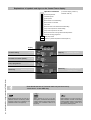
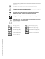
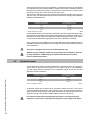
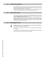
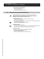
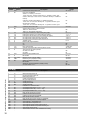
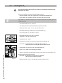
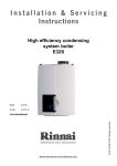
Explanations of symbols and signs on the Control Tower display.
Operation indication
0
1
2
3
4
5
6
7
8
9
A
Sun
Hot
(in the first display position by
technical read out)
No heat requirement
Ventilation phase
Ignition phase
Burner active on central heating
Burner active on hot water
Fan check
Burner off when room thermostat is demanding
Pump overrun phase for central heating
Pump overrun phase for hot water
Burner off because of to high flow water temperature
Automatic venting programme
Solar pump active
Maximum cylinder temperature achieved(>80°C)
display
Central heating
on / off
Domestic hot water (DHW)
on / off
Pump programme
on / off
Installation & Servicing Instructions ATAG Q-Solar
Mode key
2
Step key
Reset key
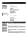
Selecting chapters
Selecting chapters
Unlocking the boiler
in case of error
From Good-read out to Technical read out (and vice versa):
- Press 5 sec. on the STEP key.
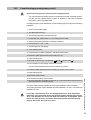
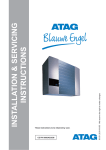
Water pressure is to low (<0,7 bar), FILL
indication remains continuously visible,
the boiler is taken out of operation. The
installation needs to be topped up.
Water pressure is to low (<1,0 bar),
flashing FILL will alternate with indication
of water pressure, boiler power of 50% is
possible. The installation needs to be
topped up.
Water pressure is to high (>2,8 bar), if
HIGH indication remains continuously
visible, the boiler is taken out of operation.
The installation pressure needs to be
decreased by draining water.
1
2
3
4
5
6
7
8
9
10
11
12
13
14
15
16
17
18
Introduction .................................................................................................................................................... 4
Regulations ................................................................................................................................................... 5
Scope of the supply ....................................................................................................................................... 7
Description of the boiler ................................................................................................................................ 7
4.1
Schematic lay out of the Q-Solar ....................................................................................................... 9
Mounting the boiler ...................................................................................................................................... 10
5.1
Dimensions .................................................................................................................................... 11
Connecting the boiler .................................................................................................................................. 12
6.1
Central Heating system .................................................................................................................. 13
6.2
Expansion vessel ............................................................................................................................ 14
6.3
Underfloor heating system (plastic pipes) ..................................................................................... 15
6.4
Gas connection ............................................................................................................................... 15
6.5
Hot water supply ............................................................................................................................. 16
6.5.1 Secondary DHW Circulation. .......................................................................................................... 17
6.6
Condensation drain pipe ................................................................................................................ 18
6.6.1 Condensate discharge ................................................................................................................... 18
6.7
Flue gas exhaust system and air supply system ........................................................................... 20
6.7.1 Flue system dimensions ................................................................................................................ 23
Solar circuit .................................................................................................................................................. 24
7.1
Expansion vessel solar circuit ........................................................................................................ 24
7.2
Filling and de-aerating the solar cicuit ........................................................................................... 24
7.3
Solar pump ...................................................................................................................................... 24
Electrical connection ................................................................................................................................... 25
8.1
Electrical connections between cylinder and boiler ....................................................................... 26
8.2
Outside sensor (optional) ............................................................................................................... 28
8.3
Solar absorber sensor .................................................................................................................... 28
8.4
Calibrating the sensors .................................................................................................................. 28
Boiler controls .............................................................................................................................................. 29
9.1
Explanation of the function keys ..................................................................................................... 30
9.2
Solar module ................................................................................................................................... 31
9.3
Functioning of the Solar module ..................................................................................................... 31
Filling and venting the installation ............................................................................................................... 32
10.1 Filling the cylinder (secundary DHW circuit) ................................................................................... 32
10.2 Central heating system (primary circuit) ......................................................................................... 33
Commissioning the boiler ......................................................................................................................... 34
11.1 Central Heating system .................................................................................................................. 34
11.2 Hot water supply ............................................................................................................................. 34
11.3 Solar circuit ...................................................................................................................................... 34
11.4 Adjustments .................................................................................................................................... 35
11.5 Activating factory settings (green key function) ............................................................................... 37
Isolating the boiler ...................................................................................................................................... 38
Commissioning ........................................................................................................................................... 38
13.1 Checking for contamination ............................................................................................................ 38
13.2 Checking of the zero pressure control ............................................................................................ 39
13.3 Checking the CO2 ........................................................................................................................... 40
Maintenance ................................................................................................................................................ 41
14.1 The frequency of maintenance ....................................................................................................... 41
14.2 Maintenance activities ..................................................................................................................... 41
14.3 Draining the installation .................................................................................................................. 43
14.4 User's instructions .......................................................................................................................... 43
14.5 Warranty .......................................................................................................................................... 43
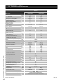
Technical specifications .............................................................................................................................. 44
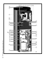
Parts of the boiler ........................................................................................................................................ 45
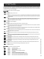
Error indication ............................................................................................................................................ 47
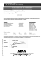
CE Declaration of conformity ....................................................................................................................... 48
The appliance should only be installed by a Competent Gas Installer.
Work on the boiler must be carried out by a competent person, (Ref: Gas
Safety Installation, Use and Regulations ) using correctly calibrated
instruments with current test certification.
Note:
Handling and storage packages:
- Handle with care. Note the instructions/symbols on the packages
Installation:
- Always read the installation manual before installing the system and putting the system into operation
Technical details:
- See page 10 for dimensions and page 41 for Technical specifications.
Installation & Servicing Instructions ATAG Q-Solar
Content
3
1
Introduction
These instructions describe the functioning, installation, use and primary maintenance
of ATAG central heating units for the United Kingdom and Ireland. Where necessary the
different regulations for each country are separately described.
These instructions are intended for the use of a Corgi registered installers or registered Bord
Gais installers in connection with the installation and putting into operation of ATAG units.
It is advisable to read these instructions thoroughly, well in advance of installation. Separate
instructions for use are supplied with the unit for users of ATAG central heating units. ATAG
is not liable for the consequences of mistakes or shortcomings which have found their way
into the installation instructions or user’s manual. Further, ATAG reserves the right to alter
its products without prior notification.
When delivering the unit, give the customer clear instructions concerning its
use; present the customer with the user’s manual and card.
Each unit is fitted with an identification plate. Consult the details on this plate to verify
whether the unit is compliant with its intended location, e.g.: gas type, power source
and exhaust classification.
On completion of the installation the installer or commissioning engineer must fill out and
complete the Benchmark commission section of the boiler log book and hand to customer
or end user for future record keeping. The Benchmark log book must also be filled out and
completed by the service agent following each service call, and returned to the customer.
A copy of the Benchmark commissioning certificate must be returned to ATAG Heating UK
Ltd along with the warranty registration card to register the appliance for the standard
warranty benefits
Installation & Servicing Instructions ATAG Q-Solar
Relevant Installation, Service and User manuals:
- ATAG Monopass
Flue system individual
- ATAG BrainQ
Digital room thermostat
- ATAG MadQ
Cascade-/Zone controller
4
Regulations
The following regulations apply to installation of ATAG central heating units:
The ATAG Q-Solar is only suitable as an individual heating appliance with
DHW supply for houses and small utility applications.
Legislation and Regulations.
Gas Safety (Installation and Use). All gas appliances must by law, be installed by a
competent person, eg. Members of CORGI and in accordance with the current Gas Safety
Regulation. Failure to install appliance correctly could lead to prosecution.
In addition to the above regulations this appliance must be installed in compliance with the
current IEE Regulations, the Building Standards (Scotland Consolidation) Regulations.
Regulations and bye laws of the Local Water Authority and the Current Health and Safety
Regulation.
Ireland:
- Irish standard 813
- Domestic gas installations
The current, Electricity at Work Regulation must be complied with and also be in
accordance with the relevant and current editions of the British Standards.
The ATAG Q boiler is a certified appliance and must not be modified or installed in any
way contrary to this Installation Manual.
Manufacturers instructions must not be taken in any way as overriding statutory
obligations.
The ATAG Q is a central heating solar unit with an integrated hot water function. These
units must be connected according to these instructions and all installation norms in
respect of the part of the unit to be connected.
Observe the following rules of safety:
- All work on the unit must take place in a dry environment.
- ATAG units must never be in operation without their housing, except in connection
with maintenance or adjustments (see Chapter 13 and 14).
- Never allow electrical or electronic components to come into contact with water.
Carry out the following tasks during maintenance, etc. to an already-installed unit:
- Shut down all programmes
- Close the gas tap
- Remove the plug from the wall socket
- Close the stop cock of the unit’s intake connection
Take note of the following when maintenance or adjustments are needed:
- The unit must be able to function during these activities; for this reason, the unit’s
supply voltage, gas pressure and water pressure must be maintained. Ensure that
these is not a source of potential danger during these activities.
Following maintenance or other activities; always check the installation of all
parts through which gas flows (using leak-detection fluid).
Following maintenance or other activities, always replace the housing and
secure it with the screw behind the door at the front of the casing.
Any electrical immersion heater installed MUST contain a thermal cutout device that will
require to be manually re-set should it operate.
Installation & Servicing Instructions ATAG Q-Solar
2
5
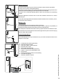
The following (safety) symbols may be encountered in these installation instructions and
on the unit:
This symbol indicates that the unit must be stored away from frost.
This symbol indicates that the packaging and/or contents can be damaged as
a result of insufficient care taken during transport.
This symbol indicates that, whilst still in its packaging, the unit must be
protected from weather conditions during transport and storage.
KEY-symbol. This symbol indicates that assembly or dismantling, must be
carried out.
ATTENTION symbol. This symbol indicates that extra attention must be paid
in connection with a particular operation.
Useful tip or advice
Gas pipe (yellow)
Solar flow pipe (yellow)
CH-flow pipe (red)
Solar return pipe (orange)
CH-return pipe (blue)
Condensate drain pipe (blue)
Cold water pipe (blue)
Expansion vessel pipe (red)
Installation & Servicing Instructions ATAG Q-Solar
Hot water pipe (red)
6
Scope of the supply
Thermal Absorber
The thermal absorber is not a
standard part of the delivery.
The thermal absorber should
be obtained from a third party.
The thermal absorber should
fit to the specifications of the
Q-Solar.
The supplied absorber
sensor PT100 ø6mm should
be mounted in the correct
position in the absorber.
Please contact the supplier
of the absorber.
4
The boiler is supplied as a 2 part system. The supplied kit is composed as follows:
Part 1:
- Cylinder(3 coils) with casing.
- Drain valve for boiler.
- Fill and drain valve for solar circuit.
- Safety valve for solar circuit.
- Expansion vessel solar circuit 18 litre.
- Solar pump with non return valve.
- Flow restrictor
- Thermometer /thermomanometer.
- Modulating 3-way valve (VC6940 Solar/CH).
- Thermostatic mixing valve.
- Temperature and pressure relief valve.
- DHW pressure reducing valve.
- DHW single check valve.
- DHW expansion vessel.
- DHW expansion relief valve.
- Tundish.
- Installation manual.
Part 2:
-
Boiler with casing and integrated:
Automatic de-aerator;
Safety valve;
3-way valve (VC2010 CH/DHW);
Fitting 28mm (3x);
T-piece 22 x 1/2" x 22 + draining valve;
Absorber sensor PT100 ø6mm;
Installation manual;
Operating manual;
Warranty card;
Benchmark logbook.
Description of the boiler
Room sealed boiler
The boiler retreives its
combustion air from
outside then discharges
the flue gasses to the
outside.
Condensing
Retrieves heat from the
flue gasses. Water
condensates on the
heat exchanger.
Modulating
Higher or lower burning
according to the heat
demand.
The ATAG Q-Solar boiler is a room sealed, condensing and modulating central heating
boiler, with or without an integrated hot water facilities which uses thermal solar power.
The boiler is provided with a compact stainless steel heat exchanger with smooth
tubes. A well thought out principal using durable materials.
The boiler burns gas for supplying warmth. The heat is transferred in the heat
exchanger to the water in the central heating system. By cooling down the flue gasses
condensate is formed. This results in high efficiency. The condensate, which has no
effect on the heat exchanger and the function of the boiler, is drained through an
internal siphon.
The boiler is provided with an intelligent control system (CMS Control Management
System). The boiler anticipates the heat demand of the central heating system or the hot
water facility.
When an outside sensor is connected, the boiler reads it and works weather dependantly.
This means that the boiler control measures the outside temperature and flow
temperature. With this data the boiler calculates the optimal flow temperature for the
installation.
Installation & Servicing Instructions ATAG Q-Solar
3
7
Stainless
Super solid kind of
steel which keeps its
quality for life. It will not
rust or erode in contrast to composition
materials, like aluminium.
The Q-Solar functions in combination with a thermal absorber. The solar circuit is a closed
pressurised glycol circuit.
The cylinder is specifically designed and constructed for this purpose. The cylinder
should not be used for other purposes.
Solar functioning in short:
The solar pump is activated as soon as the temperature of the absorber is approx. 10ºC
higher than the temperature in the cylinder ('T > 10ºC: pump on). The glycol will be
transported from the cylinder through the absorber and back. The glycol is heated in the
absorber. The heat is transferred to the sanitary water through the solar coil in the
cylinder.
The pump is deactivated as soon as the temperature of the absorber is approx. 2ºC higher
than the temperature in the cylinder ('T < 2ºC: pump off). The pump is also deactivated
if all of the sanitary water in the cylinder has reached a temperature of 80ºC. This means
that there is no chance of overheating! In addition, the cylinder is provided with a T&P valve
and the solar circuit is provided with a pressure relief valve.
The heating circuit is supplied with solar warmth from the CH coil in the middle of the
cylinder. This is especially suitable for low temperature installations, like under floor
heating systems. When the cylinder has sufficient hot water and there is a heat demand
for the heating circuit the modulating 3-way valve will be activated. The heating circuit will
be supplied by water across the CH coil of the cylinder. If the heat demand is larger than
the availability in the cylinder, the heating circuit will be heated by the gas fired boiler.
Explanation of the type indication:
ATAG Q38SC380N
Q = Type
38 = Nominal load in kW
SC = SolarCombi
380 = content of the cylinder
N= Not vented glycol solar circuit
The boiler has been tested according to valid CE* standards and has a CE* certificate
and SEDBUK A-rating.
Installation & Servicing Instructions ATAG Q-Solar
Statement: No banned materials including asbestos, mercury, CFC's have not or will not
be included in the product.
8
1.
2.
3.
4.
5.
6.
7.
8.
9.
10.
11.
12.
13.
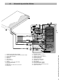
Schematic lay out of the Q-Solar
Stainless steel OSS heat exchanger
Control Management System (CMS) with Solar module
3-Way valve (CH/DHW)
Boiler pump
DHW coil
DHW sensor
CH-Solar sensor
CH coil
Modulating 3-way valve (CH-Solar)
CH-Solar return sensor
Solar coil
Drain valve and relief valve solar circuit
Solar pump
14.
15.
16.
17.
18.
19.
20.
21.
22.
23.
24.
25.
Expansion vessel
Cylinder sensor Solar (Delta-T)
Absorber sensor Solar (Delta-T)
Cylinder drain valve
DHW circulation pipe
Thermostatic mixing valve
Adjustable flow restrictor
Solar asorber
Pressure/temperature gauge
Pressure/temperature gauge
Temperature and pressure relief valve
High limit thermostat
Installation & Servicing Instructions ATAG Q-Solar
4.1
9
5
Mounting the boiler
The room where the boiler will be placed must always be frost free. To prevent heat loss
the boiler should be placed as close as possible to the absorber and, if possible, as close
as possible to the most used DHW tap(s).
It is NOT necessary to have a purpose provided air vent in the room or internal space in
which the boiler is installed. Neither is it necessary to ventilate a cupboard or
compartment in which the boiler is installed, due to the extremely low surface
temperature of the boiler casing during operation. Therefore the requirements of BS 6798,
Clause 12, and BS5440:2 may be disregarded.
The Q-Solar is a floor standing (upright) boiler. The floor on which the boiler will be placed
must be flat and of sufficient strength in order to be able to carry the boiler weight with its
total water content.
Above the boiler there must be at least 250 mm working space in order to be able to fit
a coaxial flue system or a twin supply. Take account of enough space around the boiler
in order to make connections to the boiler and installation, and allowing for access to
carry out repair and replacement of components.
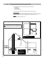
-
First position the cylinder [section 1] in the desired place and adjust it
vertically using the adjustment foot at the bottom of the cylinder.
Slide the supplied fittings (3x 28mm) on the pipe connections on which the boiler (colli
2) has to be connected. Take note of the right position (see figure 1).
Lift the boiler (Section 2) and hang it on the 2 suspension points at the top of the
cylinder. Ensure that the boiler is correctly attached to these points.
When removing the plastic sealing caps from the pipes, contaminated testing
water may be released.
Lift the boiler only by the boilers rear wall.
Installation & Servicing Instructions ATAG Q-Solar
Lifting and carrying precautions:
- Lift only a manageable weight, or ask for help.
- When lifting the boiler, bend the knees, and keep the back straight and feet apart.
- Do not lift and twist at the same time.
- Lift and carry the boiler close to the body.
- Wear protective clothing and gloves to protect from any sharp edges.
10
-
Slide the fitting upwards until the touch rim and tighten the nuts.
Move the gas pipe and expansion vessel pipe upwards and connect them.
Use only approved fittings on the gas supply.
Fittings
Figure 1
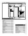
5.1
Dimensions
Ceiling
Flue system
ø80/125: min. 250 mm
ø100/150:min. 480mm
Wall
150
Q-Solar
Boiler type
Q25SC380
Q38SC380
Dimensions Q-Solar (See Table 1 and 2)
Figure 2
A Height total
1860
B Height cylinder
1830
C Width
660
D Depth
1040
E Left side / Flue gas
415
F Back side / Flue gas
920
G Centre to centre flue gas and air supply
120
H Condensate pipe c
480
J Expansion vessel pipe e
525
K Flow pipe solar absorber i
560
Q25SC380
Q38SC380
mm
Q-Solar
Boiler type
L Return pipe solar absorber u
610
M CH return pipe r
670
Air supply / Flue gas
N CH flow pipe a
730
Flue gas
P DHW pipe w
790
Gas pipe - g
ø 15x½"int.
CH flow pipe - a
ø 28x1"ext.
ø 28x1"ext.
ø 125/80
ø 80
Q Cold water pipe k
840
R Gas pipe g
930
CH return pipe - r
S DHW Circulation pipe z
870
Condensate pipe - c
T Supply cable
1040
Cold water pipe - k
ø 22x¾"ext.
DHW pipe - w
ø 22x¾"ext.
ø 32
U Supply cable
675
V Pipes c and e
744
Flow pipe solar absorber - i
ø 22
W Pipes i, u, r, a, w and k
766
Return pipe solar absorber - u
ø 22
X Pipe g
796
Expansion vessel pipe CH - e
ø 22
Y Front cylinder casing
970
DHW circulation pipe - z
ø 22
Dimensions
Table 1
Connection diameters
Table 2
Installation & Servicing Instructions ATAG Q-Solar
mm
11
6
Connecting the boiler
The boiler has the following connection pipes, which can be connected left or right to the
boiler by means of turning the knee fitting (all connections are positioned to the left
from factory);
-
The central heating pipes.
These can be connected to the installation by means of the supplied compression
fittings(1xT-piece) 28 mm x1" and the 28mmx480mm pipes. The supplied drain valve
can be fitted on the T-piece in the return pipe;
-
CH expansion vessel pipe.
On this 22mm x480mm pipe and 22mmx3/4" fitting the CH expansion vessel should
be mounted;
-
The gas pipe.
This can be fitted to the boiler with a 1/2"x15mm fitting to the boiler.Outside the boiler
the gas pipe has to be provided with a manual gas valve within 1M of the boiler;
-
The condensation drain pipe.
It consists of an oval 24 mm plastic pipe. The drain pipe can be connected to this
by means of a tundish. The drain pipe is provided with a syphon. The drain pipe can
be connected (glued) outside the boiler to a 32 mm PVC drain;
-
Cold and hot water pipes.
These consist of 22mm copper pipes and can be connected to the installation by
means of compression fittings.
-
Absorber pipes.
These consist of 22mm heat resistant insulated copper pipes. The complete
absorber circuit has to be connected with heat resistant 22mm copper pipe with the
supplied T-pieces 22mmx22mmx1/2". The supplied thermometer and
thermomanometer should be fitted to the T-pieces.
-
The flue gas exhaust system and air supply system.
It consists of a concentric connection 80/125 mm.
Installation & Servicing Instructions ATAG Q-Solar
It is recommended that isolation valves are fitted to all heating and hot water
connections to facilitate ease of future maintenance.
12
It is advisable to spray-clean all of the unit’s connecting pipes and/or to
spray-clean/blow-clean the installation before connecting it to the unit.
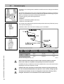
6.1
Central Heating system
Connect the central heating system according to local regulations.
The boiler pipes can be connected to the installation by means of compression fittings.
Reducers should be used for connecting to thick-walled pipe (welded or threaded).
Install the drain valve with the T-piece in the CH return pipe within reach.
It is not necessary to install a heat trap in the central heating pipes. This is already present
in the cylinder.
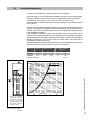
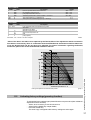
The boiler has a self-adjusting and self-protecting control system for the load and the pump
capacity. This means the temperature difference between the flow and return water is
checked. Table 3 shows the water displacement which supplies the circulation pump at
certain installation resistance.
If the installation resistance is higher than the stated value the pump will rotate at
maximum pump capacity and the load will be adjusted until an acceptable temperature
difference between flow and return water has been obtained. If, after this, the temperature
difference remains too much then the boiler will switch itself off and wait until an
acceptable temperature has arisen.
If an unacceptable temperature is detected, then the control will repeatedly try to achieve
water flow, and if this does not work then the boiler will switch off.
Boiler type
Pump type
Water flow rate
permissible installation
resistance
UPER
l/min
l/h
kPa
mbar
Q25SC380
20-60
16,2
972
32
320
Q38SC380
20-70
24,6
1478
16
Installation resistance
100%
UP
H(m)
160
Table 3
ER 2
0-70
Q38SC380
100
%U
25
%
PER
2060
UP
ER
UP
ER
Q25SC380
20
-7
0
20
-6
0
Q(m³/h)
*
When an external
installation pump is
connected to terminal
points 4,5,6 in the
Control Tower the pump
will switch parallal to
the boiler pump.
External installation pump
with low velocity header
Figure 3
pump index lines
Graph 1
Installation & Servicing Instructions ATAG Q-Solar
25
%
13
If the capacity of the boiler pump is insufficient, an extra external pump can be installed
in combination with a low velocity header in series with the boiler. The electrical side of
this external circulation pump can be connected in the Control Tower, by which means
this pump switches at the same times as the boiler pump.
The maximum absorbed current consumption of the external circulation pump may be
230 W (1 Amp). The extra external pump must be selected according to the installation
resistance and required flow.
installation height above
the expansion vessel
pre-charge pressure
of the expansion vessel
5m
0,5 bar
10 m
1,0 bar
15 m
1,5 bar
choice of expansion vessel
table 4
As standard the boiler is provided with a water filter in the return pipe of the boiler. With
this, possible contamination of the central heating water is prevented from ending up in
the boiler. The boiler is also provided with an internal safety valve set at 3 bar. This is
connected to the waste discharge together with the condensation discharge.
If all, or a large part of the radiators are provided with thermostatic radiator valves it is
advisable to use a pressure difference control (bypass) in order to prevent flow problems
in the installation.
The boiler is designed to be used on sealed systems only.
Additives in the installation water are only permitted in consultation with the
country distributor. ATAG Heating UK Ltd recommend the use of either
Fernox or Sentinel products.
6.2
Expansion vessel
Installation & Servicing Instructions ATAG Q-Solar
The central heating system must be provided with an expansion vessel. The expansion
vessel which is used should be geared to the water content of the installation.
The pre-charge pressure depends on the installation height above the mounted
expansion vessel. See table 5.
14
installation height above
the expansion vessel
pre-charge pressure
of the expansion vessel
5m
0,5 bar
10 m
1,0 bar
15 m
1,5 bar
choice of expansion vessel
table 5
All Q-Solar boilers are provided with an expansion vessel connection. This pipe is
connected between the three way valve and boiler pump. This prevents the expansion
water produced during heating or hot water operation from being closed off from the
expansion vessel, when the thermostatic radiator valves are fully closed.
In connection with correct functioning of the boiler it is necessary for the
expansion vessel to be connected to the expansion vessel pipe of the boiler.
6.3
Underfloor heating system (plastic pipes)
When connecting or using an underfloor heating system, designed with plastic pipes, or
plastic pipes are used elsewhere in the installation,one should ensure that the plastic
pipes used comply with the DIN 4726/4729 standard. It is set out in this standard that
the pipes may not have oxygen permeability higher than 0.1 g/m³.d at 40°C. If the system
does not comply with this DIN standard, the underfloor heating component will have to
be separated from the central heating appliance by means of a plate and frame heat
exhanger.
Take care that a system with platic pipes is well de-aerated and remains well de-aerated.
No recourse can be made to the terms of the warranty in the event of failure
to observe the regulations pertaining to plastic underfloor heating pipes.
Gas connection
Determine the correct diameter of the gas line and connect it to the boiler along with a
gas isolation valve within 1M of the boiler.
United Kingdom:
The gas supply must comply to the current Gas Safety Installations & Use Regulations.
Ireland:
- Irish standard 813
- Domestic gas installations
The connection to the appliance must include a suitable method of disconnection and a
gas control cock must be installed adjacent to the appliance for isolation purposes. The
nominal inlet working gas pressure measured at the appliance should be 20 mbar for Nat
gas (G20).
Make sure that the gas pipe work does not contain dirt, particularly with new
pipes.
When the boiler has to be converted from natural gas to LPG, ATAG can supply
conversion kits for this purpose. Special instructions are supplied with the kit.
Always check the installation of all of the parts through which gas flows
(using leak detection fluid)
Installation & Servicing Instructions ATAG Q-Solar
6.4
15
6.5
Hot water supply
Connection of the drinking water installation should be done according to the national
water laws.
Balanced
water supply
DHW expansion
vessel (blue)
safety group
Figure 4
The sanitary water pipes can be connected to the installation by means of compression
fittings. The cold water inlet must be provided with the supplied DHW safety group (see
figure 4) consisting of (counted in the water flow direction):
- Pressure reducing valve with integral strainer
- Check valve
- Core unit
- Expansion vessel 6bar (potable water, blue)
- Expansion valve with tundish
The cylinder is provided with a temperature and pressure relief valve (T&P valve) on top
of the cylinder (see figure 5).
Install the tundish of the T&P valve according figure 7 and table 6.
T&P valve
Figure 5
installation of the T&P valve tundish
Installation & Servicing Instructions ATAG Q-Solar
tundish
16
Figure 6
Figure 7
Valve
outlet
size
Minimum size
of discharge
pipe (D1)
Minimum size of
discharge pipe
from tundish (D2)
28mm
up to 9m
1.0m
G 3/4"
22mm
35mm
up to 18m
1.4 m
42mm
up to 27m
1.7m
dimensions discharge pipes T&P valve
Maximum resistance
allowed, expressed as a
length of straight pipe
Resistance created
by each bend or
elbow
table 6
Above mentioned items may be used for their specific purposes only and
have to be visible to occupants and kept away from electrical devices.
If a DHW secondary circulation line has to be installed take account of the extra volume
regarding the size of the expansion vessel.
Cylinder relief valve connections should not be used for any other purpose and
no valve should be fitted between the expansion valve and the storage cylinder.
Thermosat and thermal cut-out are integrated in the boiler and may not be
changed. Therefore it is not allowed to fit an immersion heater.
Take account of the hardness of the water. Take precautions to prevent
scaling in the cylinder.
In regions with a water hardness value higher than 267ppm (2,67 mmol/l),
calcium deposits should be removed from the cylinder on a regular basis. If
problems occur when using sanitary water with a chlorine content higher
than 150 mg/l, no recourse can be made to the terms of the warranty.
The hardness of the water is variable in Great Brittain and Ireland. The water company
can provide exact information about this.
Secondary DHW Circulation.
In case of long DHW pipe runs one can connect a secondary circulation pipe to the QSolar. This improves the comfort because the waiting times can be reduced to a few
seconds
The return of this pipe is connected to position Z on the Q-Solar.
The pump of this secondary circulation is not part of the delivery and has to be sourced
elsewhere. Please make sure that this is a DHW circulation pump.
It is good practice to put a time clock on the pump so that it only runs during hours of
possible hot water usage.
Installation & Servicing Instructions ATAG Q-Solar
6.5.1
17
6.6
Condensation drain pipe
ATAG boilers produce condensate. This condensate must be drained otherwise the
boiler will not function.
The collecting condensation drain pipe should be connected to the drain by means of an open
connection. This means the possibility of drain gases ending up in the boiler is prevented.
The drain connection should have a minimum diameter of 25mm.
Connect the condensation drain pipe according to the local regulations.
The following components are connected to the collective condensation drain pipe:
- Condensation discharge;
- Safety valve;
Draining of the condensation water to the external rain guttering is not
permitted in view of the danger of freezing.
Before putting the boiler into operation fill the siphon with 300 ml of water.
The condensate pipe must be run using suitable corrosion resistant materials
(eg. plastic).
6.6.1
Condensate discharge
ATAG Condensing boilers have the top SEDBUK band A Classification for high energy
efficiency in heating and domestic hot water.
All ATAG wall hung gas fired condensing boilers contain a syphonic condensate trap to
collect and realease condensate.
The ammount of condensate formed is determind by the type of boilers and the water
temperature produced by the boiler.
Condensate pipework.
Use plastic pipe work of a diameter no less then 25mm.
Installation & Servicing Instructions ATAG Q-Solar
Routing of the pipe work,
18
Wherever possible, the condensate pipework should be routed internally to prevent
freezing.
The condensate pipework must fall at least 50mm per metre towards the outlet and take
the shortest possible route
Support the pipe at least every 50 cm for near horizontal sections and 1 metre for vertical
sections
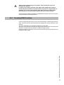
External pipework
A
The pipework should be kept to a minimum and the route as vertical as possible.
Do not exceed 3 metres outside the dwelling.
Terminate as close to the ground or drain as possible (below the grating and above the
water level) while still allowing for safe dispersal of the condensate.
Connection of a condensate drainage pipe to a drain may be subject to local building
controls.
100mm
Min.
B
L
C
75mm
Min.
F
D
Pipework subjected to extreme cold or wind chill conditions should be in a 40mm
diameter pipe.
A
Protect all external pipework with weather resistant insulation and, if necessary, box in,
to reduce the risk of freezing.
Making it safe.
L
C
D
A
Condensate pipework must not leak, freeze or block up.
Condensate traps must be filled before firing the boiler to prevent the possibility of
potential harmfull flue products evacuating via the condensate route.
Do not dispose condensate into a water recovery system where it is recaimed for reuse.
Condensate can be discharged into a rainwater hopper which is part of a sewer carrying
both rain water and foul water.
Final discharge options.
E
The condensate pipe can only terminate into any one of the five areas as shown in the
diagrams on this page.
C
A
B
C
D
E
F
G
H
J
K
L
A
100mm
Min.
B
C
L
75mm
Min.
D
F
-Condensate from boiler syphon/trap
-Sink with internal overflow
-25mm dia. Plastic condensate pipe
-External drain or gully
-Internal soil and vent stack.
-Servicable condensate trap (75mm min.)
-300mm x 100mm dia. sealed plastic tube.
-Ground level
-Drainage holes facing away from the building
-Lime stone chippings
-Weather resistant insulation
A
100mm
G
H
12mm
L
300mm
25mm
C
25mm
G
50mm
H
K
J
25mm
Min.
400mm
MIN.
25mm
Installation & Servicing Instructions ATAG Q-Solar
450mm
Min.
UP TO 3
STOREYS
19
6.7
Flue gas exhaust system and air supply system
The flue gas exhaust system and air supply system consists of:
- Flue gas pipe;
- Air supply pipe;
- Roof or wall terminal.
The flue gas exhaust system and air supply system must comply with:
United Kingdom:
The flue gas outlet and air supply installation must comply with the current regulation
requirements. BS 715, BS 5440-1:2000 and BS5440-2:2000 and BS 715.
Ireland:
- Irish standard is 813 section 9.10.1
All flue gas parts, which are outside the fire
resistant cover, need to be in stainless steel.
PP
SS
Air filter
Open boiler
BoilerClass B
Free exhaust area
Installation & Servicing Instructions ATAG Q-Solar
SS
PP
20
PP
PP
SS
PP
PP/MW
PP/MW
PP/MW
Boiler Class C
Permitted only
when the air
intake and the flue gas
outlet are in the same
pressure area.
Room sealed system
Open boiler en roomsealed system
figure 8
The appliance connection diameter is 80/125 mm, to which the flue gas outlet and air
supply system can be fitted, with or without elbow pieces. The maximum permissible
pipe length is set out in Table 8.
It is also possible to use a parallel pipe connection of 2x 80mm. In this case a seperate
cover 125mm should be ordered. Art.nr. S4323410.
We advise building a simple flue gas and air supply system using table 7. For further
information about the available components of the flue gas and air supply system we
recommend you consult the Monopass Flue systems.
The ATAG flue gas system is meant and designed soley for use on ATAG central heating
boilers adjusted for Nat gas or LPG. The maximum flue gas temperatures are below 70°C
(full load 80/60°C)
The proper operation can be influenced harmfully by changes of, or adjustments to the
correct set up.
Possible warranty claims will not be honoured if incorrect changes result in non
compliance with the installation manual or local rules and regulations.
The flue gas systems described in this document are solely suited for ATAG central
heating boilers of the ATAG boiler range. For this purpose the CE Certificate has been
supplemented under the Gastec nr: 0063BQ3021, 0063AS3538 and 0063AU3110.
The flue gas system should be built up using only ATAG program products.
Combinations with other brands or systems without written permission from ATAG
Heating is not permitted and will invalidate any warranty.
Horizontal flue systems should always be installed sloping towards the boiler, in order
to avoid condensate lying in the flue system.
The minimum gradient is 50mm/Mtr. With the condensate running back to the boiler the
risk of ice forming at the terminal is reduced.
minimum
distance
terminal position for fan assisted boiler
A
figure 9
directly below an open window or other opening
mm
(e.g. air brick)
300
B below gutters, soil pipes or drain pipes
mm
75
C below eaves
mm
200
D below balconies or car port roof
mm
200
E from vertical drain pipes and soil pipes
mm
75
F from internal or external corners
mm
300
G above ground or below balcony level
mm
300
H from a surface facing a terminal
mm
600
I
from a terminal facing a terminal
mm
1200
J
from an opening in the car port (e.g. door
window) into dwelling
mm
1200
K vertically from a terminal on the same wall
mm
1500
L horizontally from a terminal on the same wall
mm
300
M horizontally from a vertical terminal to a wall
mm
300
Dimensions
Installation & Servicing Instructions ATAG Q-Solar
The terminal should be located where dispersal of combustion products is not impeded
and with due regard for the damage or discolouration that might occur to building products
in the vicinity (see fig 9).
table 7
21
In certain weather conditions condensation may also accumulate on the outside of
the air inlet pipe. Such conditions must be considered and where necessary
insulation of the inlet pipe may be required.
In cold and/or humid weather water vapour may condense on leaving the flue terminal. The effect of such ‘plumeing’ must be considered.
The terminal must not be located in a place where it is likely to cause a nuisance.
For protection of combustibles, refer to IS 813 section 9.10.1. where the terminal is
less than 2m (6.6ft) above a pavement or platform to which people have access
(including) any balcony or flat roof the terminal must be protected by a guard of
durable material.
A suitable guard is available from the country distributor.
Where a terminal is fitted below a window which is hinged at the top, and/or
where the hinge axis is horizontal, and the window opens outwards, the
terminal should be 1m below the bottom of the window opening.
If the boiler is to be located under stairs, a smoke alarm meeting the
requirements of I.S. 409 or equivalent must be fitted.
The flue must be terminated in a place not likely to cause a nuisance.
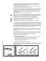
For horizontal sections, the outlet system should always be fitted on an incline (50
mm/m) sloping down towards the appliance so that no condensation water is able to
accumulate in the outlet system. The chances of icicles forming on the roof outlet is
minimised by causing the condensation water to run back towards the appliance. In
the case of horizontal outlets the inlet system should be fitted on an incline sloping
down towards the outside to prevent rainwater from coming in.
The appliance produces a white wisp of condensation (plumeing). This wisp of
condensation is harmless, but can be unattractive, particularly in the case of outlets
in outside walls.
At this time there are 2 different ways of connecting the flue gas/air intake system.
The flue gas duct for the 60/100, 80/125 and 100/150 are push fit connections, see
figure 11. The air intake for the 60/100 is a clamp ring connection.
These two types are not interchangeable.
Installation & Servicing Instructions ATAG Q-Solar
Cutting the pipe goes as follows:
- Take out the inner tube by turning it until it releases from its security position;
- Cut just as much from the air intake part as from the flue gas part;
- Take off the burrs from the cutting edge to prevent cutting the seals;
- Click the pipes back together again.
22
Use silicon based grease to simplify the fitting
When mounting the flue gas system, pay attention to the flow direction. An arrow on
the product points this out. It is not permitted to mount a system upside down and
will lead to complaints.
minimum height flue
Figure 10
Dismantlement and shorten pipes
Figure 11
6.7.1
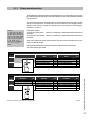
Flue system dimensions
The flue diameter is determined by the total length of the run, including for the connection
pipe, elbow fittings and terminal covers etc and the type and number of boilers installed
into the system.
An undersized flue pipe can lead to disorders. Look at table 8 for the choice of the system
and the correct diameter. The table below shows the maximum flue lengths with the
different boiler outputs. A longer flue gas length can be achieved by increasing the
diameter to ø 100mm.
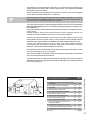
Example:
A 25kW with a concentric
flue gas system ø80/125mm
has according to the table a
maximum flue straight length
of 31m In the system that is
going to be put in there are
2 x 45° bends, so the
maximum flue gas length is
31 – ( 2 x 1.1 ) = 28.8
meters.
Explanation table 8:
Two pipe flue gas system: maximum noted length = distance between boiler and roof
terminal A
Concentric flue gas system: maximum noted length = distance between boiler and roof
terminal B
When using bends the noted value behind every bend should be deducted from the
maximum straight length.
Pipes with 60/100 diameter are only permitted on wall terminals in combination
with ATAG boilers upto 25kW.
Two pipe flue system + chimney lining
ø80mm
Maximum straight lenth 80
87° bend resistance length
45° bend resistance length
Maximum straight lenth 80
87° bend resistance length
45° bend resistance length
16-25 kW
26-38 kW
A
in m
31
-1,5
-0,8
18
-1,5
-0,8
ø100mm
Maximum straight lenth 100
87° bend resistance length
45° bend resistance length
Maximum straight lenth 100
87° bend resistance length
45° bend resistance length
A
in m
40
-1,8
-0,9
39
-1,8
-0,9
B
in m
31
-2,8
-1,1
13
-2,8
-1,1
ø100/150mm
Maximum straight lenth 100/150
87° bend resistance length
45° bend resistance length
Maximum straight lenth 100/150
87° bend resistance length
45° bend resistance length
B
in m
40
-2,6
-1,1
34
-2,6
-1,1
ø60/100mm
16-25 kW Maximum straight lenth 60/100
87° bend resistance length
45° bend resistance length
26-38 kW
Dimensions flue gas system and air supply system
Table 8
Installation & Servicing Instructions ATAG Q-Solar
Concentric flue system
B
in m
ø80/125mm
12 Maximum straight lenth 80/125
-1 87° bend resistance length
-1 45° bend resistance length
Maximum straight lenth 80/125
87° bend resistance length
45° bend resistance length
23
7
Solar circuit
The cylinder of the Q-Solar is provided with a system to connect to a glycol solar system.
The cylinder can be recognized by the type name on the data plate of the cylinder.
SC380N
N = non vented. This system is a pressurised closed system. The system has to be filled
with glycol. Follow the instructions of the supplier of the solar absorber.
7.1
Expansion vessel solar circuit
The cylinder of the Q-Solar is provided with an 18 liter expansion vessel. Take this into
account when designing and calculating the solar circuit.
7.2
Filling and de-aerating the solar cicuit
Filling and de-aeration of the solar circuit should be executed according to the
instructions of the supplier of the absorber.
When the system is filled and de-aerated the switch (Solar) on the Control Tower must
be switched on (1).
When the boiler has to be operated without connection to a solar circuit, the switch
[solar] on the Control Tower should be switched off [0] and the flat cable should be
removed from the Solar Module. The Solar Module [PCB] is situated inside the
Control Tower.
7.3
Solar pump
The solar pump is factory set at a pump head of 4 mtr. When necessary the pump can
be set to a pump head of 6 mtr. In this case the electrical bridge in the connection terminal
on top of the solar pump should be changed according to figure 12.
Installation & Servicing Instructions ATAG Q-Solar
Pump head 4 Meter:
Pump head 6 Meter:
24
Bridge between 2-6
Bridge between 2-7
connection terminal solar pump
Figure 12
8
Electrical connection
The appliance complies with the CE Machinery Directive 89/392/EEC. The EC Low Voltage
Directive 72/23/EEC and the EC EMC Directive 89/336/EEC.
A 230V -50Hz mains electrical supply is required fused externally at 5A.
The installation must continue to comply with:
United Kingdom:
- IEE regulations and Part P.
- the national rules for electrical installations.
Ireland:
- the ECTI national rules for electrical installations
The appliance must be connected to an earthed socket. This must be visible and within
reach.
The following general stipulations also apply:
- No changes may be made to the wiring of the appliance;
- All connections should be designed in accordance with the enclosed regulations.;
- Should it be necessary to change it, the mains power supply cable may only be
replaced with an ATAG mains power supply cable (item No. S4320100).
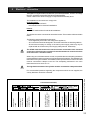
The ATAG room thermostat and controls must be connected to their allocated
connections. All other types or makes of room thermostats or controls which are
used must have a Volt free contact.
When using an on/off thermostat or control, it is possible that an anticipating resistance
must be installed in order to prevent too high temperature fluctuations. As a standard rule
this means mercury thermostats. This resistance wire is present in the Control Tower and
must be connected to clamps 23 and 27. The anticipating resistance in the room
thermostat has to be set at 0.11 A.
The high limit thermostat of the cylinder must be connected to clamps 24 and 25.
Connection terminalQ
24 Volts
maximum 100 mA
High limit thermostat
On/off thermostat or
control (Volt free)
ATAG outside sensor
internal or external
three-way valve motor
and cylinder sensor
230 Volts
230 Volts for
external control
230 Volts for
external pump
mains power
supply
Connection terminal
ATAG
room thermostat
tabel 6
boilercombinaties
Figure 13
Installation & Servicing Instructions ATAG Q-Solar
For more detailed questions regarding the components which are not supplied, the
country distributor should be contacted.
25
8.1
Electrical connections between cylinder and boiler
The following components should be connected according to figure 14 and 15:
A
-
B
-
C
-
D
-
E
-
F
-
G
-
Solar absorber sensor T 7
Pass sensor cable through cable feed A to the side of the cylinder. Connect wires
from the absorber to the connector with the green wires. Follow the instructions
of the supplier of the absorber.
Solar cylinder sensor T 6
Pass the red sensor cable through cable feed B and connect the wires to the
connector with the red cables.
CH - Solar sensor T 8
Pass the white and grey sensor cable through cable feed C and connect the wires
to the CH - Solar sensor T 8 on the cylinder.
CH - Solar return sensor T 9
Pass the white and black sensor cable through cable feed C and connect the wires
to the CH - Solar return sensor T 9 on the CH return pipe.
Modulating 3-way valve (VC 6940 CH-Solar)
Pass the connector with yellow, purple and blue cable through the cable feed D
and connect it to the actuator of the modulating 3-way valve.
Solar pump
Pass the cable from the solar pump through the cable feed E and connect it to
the connector behind the Control Tower.
DHW sensor T 3
Pass the sensor cable through the back side of the boiler E and connect it to the
DHW sensor on the cylinder.
Caution! When the solar circuit is in operation the solar circuit pipes can
reach high temperatures (> 120°C).
Prevent physical contact and contact with electrical wiring.
The solar pipe lines should be insulated with UV and temperature resistant material.
Installation & Servicing Instructions ATAG Q-Solar
Follow the instructions of the supplier of the absorber for correct installation.
26
cable feed through
cable feed through
electrical connections
Figure 14
Figure12
15
figuur
27
Installation & Servicing Instructions ATAG Q-Solar
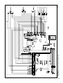
electrical diagram
figure 16
8.2
Outside sensor (optional)
Place the outside sensor on a north facing wall. The outside sensor should be placed in
such a way, that sun, snow and/or air streams of ventilation do not have any adverse
influence. Do not place the sensor on a chimney.
Connect the outside sensor with a 2-core cable of 0,75mm2 on connection points 18 and
19 of the connection terminal in the Control Tower (see figure 13 and 16)
8.3
Solar absorber sensor
The PT100 absorber sensor T7 (green) is part of a kit comprising the PT100 Solar cylinder
sensor T6 (red) and the delta-T control in the Solar Module. The functioning of the DeltaT control is described in chapter 9.2 and 9.3.
Connect the absorber sensor according to chapter 8.1. The sensor cable can be
lengthened to a maximim of 10 meters of 2 core cable of 0,75mm2. If the sensor cable
is lengthened with more than 10 meters of cable the sensor must be calibrated to get
equal resistance values (see chapter 8.4)
8.4
Calibrating the sensors
Calibrating the sensors is only necessary when a sensor cable is lengthened
to more than 10 meters of 0,75mm2 cable.
On the Delta-T controla (Solar module) are 2 PT100 sensors (cylinder T6 and absorber
T7) connected.
Installation & Servicing Instructions ATAG Q-Solar
When a sensor cable is lengthened to more than 10 meters a parameter adjustment has
to be made. Please contact ATAG Heating for guideance.
28
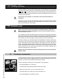
9
Boiler controls
The boiler is provided with a fully automatic microprocessor control, called CMS Control
Management System. This control simplifies operation by undertaking all major control
functions. Initially when power to the unit is switched on it will remain on standby. There
is no indication Led on, untill one of the programme keys is pressed. The control panel
display will show the relevant state. When the installation is empty of water the display
will show FILL.
The various parameters can be called up in two ways:
The Good-state or standard read out
The first way shows a simple display read out.
The boiler in operation will always show 'Good'. When a message is necessary this will
be shown instead of Good.
Technical read out
The second way is a technical read out. In normal situations the following will be shown:
• on the left the status in which the boiler is active;
• on the right the flow temperature;
• the water pressure in the installation.
When a message (error or blocking code) is necessary this will be shown instead of the
technical read out..
To switch over from the Good-state to the Technical read out (and vice versa):
- Press for 5 sec. on the STEP-key.
When the system has been filled the automatic venting program starts, when a programme
has been selected, by pressing the key for Central Heating, DHW or pump programme
(
,
of
). The programme takes 17 minutes and stops automatically. After this
the unit will function normally. (See also 'Filling and venting the boiler and installation).
Installation & Servicing Instructions ATAG Q-Solar
On a call for heating or hot water the control system will select the required water control
temperature. This water temperature is called the T-set value. On a call for central heating
the boiler ignites first at low output. The output is then changed slowly to match the load
required. The boiler operates in this way to avoid excessive water noises and temperature
overshoot. On a call for hot water supply the T-set value of central heating return water
temperature is monitored. Depending on the amount of sanitary water which is withdrawn
from the DHW cylinder, the central heating return water temperature, from which the input
is adjusted, will vary.
29
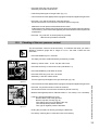
9.1
Explanation of the function keys
When the pump is
switched on continuously
it can lead to undesired
heating up of the central
heating system during
the summer.
-
Central Heating programme key.
Switching the Central Heating on or off (Led on/off);
-
Hot Water programme key.
Switching the Domestic Hot Water (DHW) facility on or off (Led on/off);
-
Pump programme key.
adjusts the pump to continuous water circulation in the central heating system (Led
on), or according to the pump overrun times on the relevant programs (Led off);
•
Mode-key.
After briefly pressing, a selection of the data chapters can be retrieved.
After pressing for 5 seconds it is possible to enter the code as described in chapter
11.3;
Step-key.
After briefly pressing, the water pressure can be retrieved and pages per chapter
can be retrieved.
After pressing for 5 seconds it switches from the Good-state to technical read out and
vice versa;
Reset-key.
After briefly pressing, for:
- unlocking errors;
- ending the access code;
After pressing for 5 seconds an operating stop is made, for example, for activating
the automatic venting programme.
•
•
Installation & Servicing Instructions ATAG Q-Solar
Some keys have other functions.These functions are only active when according to the
procedure described in chapter 11.4, adjustment has to be changed or data must be
retreived from the CMS.
The other functions are:
30
-
Central Heating programme key :
-
Hot Water programme key:
Pump programme key :
-
Step-key:
+ function.
- function.
store-function, which means that by means
of this key a modified setting is confirmed.
scrolling in a data chapter.
9.2
Solar module
In the Control Tower, next to the CMS for the boiler, is the Solar Module [Delta-T controller]
to control the solar circuit. This control is completely separate from the boiler control and
can be switched off with the switch on the Control Tower.
Functioning of the Solar module
The Delta-T control of the Solar module functions in combination with 2 solar sensors.
One is situated on the cylinder, the second one is situated in the absorber (follow the
instructions of the supplier)
The inputs for the sensors have a temperature range of -40°C to +175°C. The maximum
temperature difference between cylinder and absorber amounts to -80°C to +175°C. The
Delta-T controller works on the basis of the measured temperature difference between
the sensor in the cylinder and the absorber. The absorber pump is activated if the
temperature in the absorber is approx. 10°C higher than the temperature in the cylinder.
The absorber pump switches off automatically as soon as this temperature difference has
dropped to approx. 2°C.
The pump also switches off automatically as soon as the cylinder has reached a
temperature of 80°C. The controller allows the pump to restart once the temperature of
the cylinder has dropped to 75°C.
When there is a heat demand on CH and the cylinder contains sufficient heat (solar) the
modulating 3-way valve will pass to the CH circuit via the Solar CH coil in the cylinder.
Sensor T8 and T9 will measure the temperature difference and together with the standard
data from the CMS it decides if heat may be retreived from the cylinder or that the boiler
has to fire. DHW demand is always priority and if the cylinder contains insufficient heat
due to insufficient solar influence, the boiler will operate.
Installation & Servicing Instructions ATAG Q-Solar
9.3
31
10 Filling and venting the installation
Fill the following parts of the installation:
- cylinder (secondary DHW circuit)
- solar circuit (see page 21)
- central heating system (primary circuit)
10.1
Filling the cylinder (secondary DHW circuit)
Do not manually open the temperature and pressure relief valve or
expansion relief valve for venting purposes (any foreign matter in the
pipework may cause damage to the valve seats).
To fill the hot water cylinder:
- Open the isolation valve in the cold feed supply to the cylinder;
- Open all hot water outlet taps;
- Close the hot water taps as water runs freely out of each. This will remove any air within
the cylinder and outlet pipework;
- Swich on the boilers DHW programme button.
To flush the cylinder:
- Allow the cylinder to fully heat up;
- Turn off the boilers hot water programme, and open all hot water outlet taps until the
water runs cold. This will flush the cylinder and pipe work through.
Installation & Servicing Instructions ATAG Q-Solar
To drain the cylinder:
The cylinder can be drained by means of the drain tap fitted.
- Close the cold feed supply isolation valve;
- Open all hot water outlet taps;
- Open the cylinders drain tap until water stops flowing.
32
Central heating system (primary circuit)
Do not use boiler pressure relief valve for venting purposes.
-
The complete primary heating system must be flushed out with cold and hot water.
Fill and vent the central heating system as detailed in the boiler installation
instructions. Use only potable water.
For filling or topping up the installation you use the filling loop according to the following
procedure:
1 Switch on the power supply;
2 The diplay will show FILL;
3 All functions off (heating, DHW and pump);
4 Push briefly the 'STEP'-button: P x.x = water pressure in bar;
5 Open the filling loop (Indication on display increases);
6 Fill up slowly to 1.5 to 1.7 bar;
7 STOP appears on the display;
8 Close the filling loop;
9 De-aerate the complete installation, start at the lowest point;
10 Check the water pressure and if necessary top it up;
11 Close the filling loop;
12 Activate the functions in use (heating
, DHW
and/or pump
);
13 If A xx appears on the display, wait for 17 minutes.
Do not press the Reset button as this restrarts this process;
14 Check the water pressure and if necessary top it up to 1,5 to 1,7 bar
15 Close the filling loop;
16 Press the ‘STEP’-button;
17 Be sure that the filling loop is closed.
18 After the automatic de-aeration programm (A xx) is finished the boiler will return to
the Good state or Technical read out.
Check the water pressure regularly and top up the installation when necessary.
The working pressure of the installation should be between 1.5 and 1.7 bar when the
installation is cold.
It can take a while before all air has disappeared from a filled installation.
Especially in the first week noises may be heard which indicate the presence
of air. The automatic air vent in the boiler will make this air disappear, which
means the water pressure can reduce during this period and therefore topping up with water will have to be done.
Installation & Servicing Instructions ATAG Q-Solar
10.2
33
11 Commissioning the boiler
Before the boiler is fired, ensure that the boiler and the system are well vented and free
of air. Purge the gas line between the gas meter and the boiler and carry out a gas
soundness test as specified in the current Gas Safety Installation & Use Regulations.
The boiler does not require adjustment of the burner pressure and air quantity because
it is self adjusting and is factory set at the correct value.
11.1
Central Heating system
Provided there is a heat requirement from the thermostat or control, the central heating
programme will be put into operation by means of the
key (central heating
programme). The circulation pump will start circulating and the boiler will start the
burner.
11.2
Hot water supply
Provided there is a heat requirement from the cylinder, the hot water programme will be
put into operation by means of the
11.3
key (hot water programme).
Solar circuit
Switch on the solar circuit by means of the (solar) switch on the Control Tower. When
the temperature differnce between absorber and cylinder >10°C the solar pump will
switch on and will function according to the control of the Solar module described on page
28.
Installation & Servicing Instructions ATAG Q-Solar
When the boiler has to be functioning without the connected solar circuit, the switch
(solar) on the Control Tower should be switched off (0) and the flat cable should be
removed from the Solar module. The Solar module (PCB) is situated on the back inside
the Control Tower.
34
11.4
Adjustments
When the boiler is installed it is in principal ready for use. All adjustments of the boiler
control are already pre-programmed for a heating system with radiators/convectors with
a flow temperature of 85°C. The adjustments are described in the Parameter chapter on
page 33.
In certain cases adjustment have to be altered in case of :
-
Lower flow temperature
Multiple boiler installations (cascade)
Read through the Parameter chapter to adjust the boiler to its installation.
Contact ATAG Heating in case of doubt.
Please follow the next procudere to alter adjustments:
Altering adjustments
STEP 1
Press the Mode-key for 5 secondss.
The display shows COdE followed by an arbitrary number;
STEP 2
Press by means of the + or the - key until the code C123 is shown;
STEP 3
Press the STORE-key to confirm the code (code blinks1 x).
Now you have acces to the installer level. There are 4 chapters:
•
PARA
Parameters
•
INFO
Information chapter (no adjustments possible)
•
SERV
Service chapter
•
ERRO
Error-chapter (no adjustments possible)
STEP 4
Press briefly the MODE-key to select one of the 4 chapters, i.e. PARA;
STEP 5
Press briefly once or more on the STEP-key to select a Parameter
(parameter visible on the left, value on the right) ;
STEP 6
Alter the value, if necessary/possible, by means of the + or the - key
STEP 7
Press briefly on the STORE-key to confirm the alteration.
When you have to change more values, repeat from step 5.
STEP 8
Press once or more on the MODE-key until StBY or Good is shown:
After a few seconds the text StBY will be replaced by the technical read-out
or Good-state (Depending from the position the acces code is keyed in)
When you want to return from an arbitrary position to the original read out press
once or more on the MODE-key until StBY is shown.
After 20 minutes if no single key is used, the display will return automatically to its original
read-out (Good state or technical read out)
Installation & Servicing Instructions ATAG Q-Solar
The content of the chapters is described on the following pages.
35
Parameter-Mode
PARA
Factory
1
70°C
2*
02
3
4*
5*
6*
7*
10*
11*
14
15*
23
31
36
43
45
48
49
89
.
max.
00
2.3
1.4
-10
0°C
0°C
5
0
-3°C
63°C
0
max.
0
25% (50%)
100%
00
.
Description
maximum flow temperature CH
type of CH installation:
radiators; air heating; convectors:
T max. flow 85°C; K factor heating line 2.3; gradient 5°C/min; gear
radiators with large surface areas or underfloor heating as additional
heating:
under floor heating with radiators as additional heating:
T max. flow 60°C; K factor heating line 1.5; gradient 4°C/min; gear
full under floor heating:
T max. flow 50°C; K factor heating line 1.0; gradient 3°C/min; gear
maximum power CH in kW
control principal with on / off thermostat:
100 % on / off thermostat
100 % on / off weather dependant
heating line K-factor (see also heating line graph)
heating line exponent (see also heating line graph)
heating line climate zone (see also heating line graph)
fine adjustment heating line day temperature
fine adjustment heating line night temperature
gradient speed
booster after night reduction:
no
yes
Frost Temperature
Cylinder temperature with external cylinder sensor
Type of three way valve cylinder
VC 2010 / VC 8010
VC 6940
Maximum power DHW in kW
No function
Minimum pump capacity (Q60S)
Maximum pump capacity Heating
Address of boiler in cascade
No function
ATAG Bus thermostat (BrainQ, MadQ, Smart)
Cascade boiler 1 to 8
.
Range
20 - 85°C
01
02
03
04
min-max
00
01
0.2 - 3.5
1.1 - 1.4
-20 - 0
-5 to 5°C
-5 to 5°C
0 - 15
00
01
-20 to 10°C
40 - 80°C
00
01
min-max
00 - 01
25-100 %
40-100 %
-01
00
00 - 07
.
Info-Mode
Installation & Servicing Instructions ATAG Q-Solar
INFO
.
36
Factory
.
1
4
5
7
8
16
17
18
20
21
22
23
24
25
26
32
37
46
200
201
202
203
204
205
°C
°C
°C
°C
°C
%
kW
kW
GJ
GJ
GJ
Std
Std
Std
Std
Std
Std
°C
°C
°C
°C
h
h
.
.
Description
.
.
flow water temperature T1
return water temperature T2
DHW temperature T3
outside temperature T4
flue gas temperature T5
actual power in %
actual power in kW
actual load in kW
indication bus communication
consumption total in GJ (.. x 33 = .. m3)
consumption CH in GJ (.. x 33 = .. m3)
consumption DHW in GJ (.. x 33 = .. m3)
total number of burner run hours
number of burner run hours CH
number of burner run hours DHW
total number of hours counter
total number of run hours pump CH and DHW
within how many hours is service required
Solar-Cylinder - Temperature T6
Solar-Absorber-Temperature T7
Solar-Cylinder-Temperature Heating coil T8
Solar-Cylinder-Return temperature Heating T9
Solar pump running hours
Total number of hours solar contribution to heating
.
Service-Mode
SERV
1
2
3
4
200
201
Value
OFF
OFF
OFF
OFF
0
0
Description
boiler in operation with burner function on
fan adjustable and burner off
pump adjustable with burner on
showroom position ON = active and OFF = non active
Solar pump Manual (1) / Automatic (0)
Three port valve solar-heating open (1) / closed (0)
Range
OFF - max.
OFF - max.
OFF - max.
ON - OFF
0-1
0-1
.
.
.
.
Error-Mode
ERRO
Value
Err.L - Err.5
1
2
3
°C
4
°C
5
kW
6
%
Description
Last saved error until 5 last predecessing errors
error code
operation status boiler
flow water temperature T1
return water temperature T2
load
pump capacity
Parameter-, Info-, Service- and Error-chapters
Table 9
outside temperature in °C
heating line adjustments Parameter Step 6 and 7
11.5
graph 2
Activating factory settings (green key function)
To activate the factory settings again please follow the next procedure (Note: all altered
adjustments will be set back):
- Select, when necessary, the technical read out;
- Select with the MODE-key chapter PARA;
- Press the STORE-key.
The word "Copy" will appear and the factory settings are active again.
Installation & Servicing Instructions ATAG Q-Solar
flow water temperature in °C
* Most of the data in this table can be optained by the BrainQ. Most of the adjustments which are stated in
this table are unnecessary when in combination with the ATAG BrainQ thermostat and will be taken care
of by the BrainQ itself and do not have to be adjusted. For further information regarding the BrainQ
thermostat, please refer to the ATAG BrainQ installation manual.
37
12
Isolating the boiler
In some situations it may be that the entire boiler must be switched off. By switching
off the three keys with the lamps for central heating, hot water and pump programme
,
or
), the boiler is switched off. Leave the plug in the wall socket, which
(
means the circulation pump and the three-way valve are activated once every 24 hours
in order to prevent jamming.
In the event of frost danger it is advisable to drain the boiler and/or the
installation.
Alternatively you can drain the central heating system, boiler and CBS cylinder. Please
contact your Installer. The cylinder can be drained almost completely (> 80%) using the
drain valve at the bottom of the cylinder .
13 Commissioning
Work on the boiler must be carried out by a competent person, (Ref: Gas
Safety Installation, Use and Regulations ) using correctly calibrated instruments
with current test certification.
To commission the boiler the casing has to be removed. The casing is locked with a
screw behind the door on the front, and the top of the casing is hooked behind a locking
edge. After removing this screw the casing must be lifted at the bottom by which means
it is released from the locking edge. Then the casing can be removed forward.
The boiler settings, such as burner pressure and adjustment of the air quantity are
unnecessary, due to the fact that the boiler operates with a so-called zero pressure
control. This means the correct gas quantity is controlled by the suction operation of
the fan. The fine adjustment which is carried out at the factory is once-only, which
means that adjusting of these values is unnecessary. When replacing the gas valve,
venturi and/or the fan, the zero pressure and the CO2 will require checking, and if
necessary, adjusting to the correct value.
Installation & Servicing Instructions ATAG Q-Solar
Always check the installation of all parts through which gas flows (using leak
detection fluid).
38
13.1
Checking for contamination
In order to be able to check the boiler for contamination in the following years it is advisable
to measure the maximum air displacement in the boiler when putting the boiler into
operation. This value can be different with each type of boiler.
In order to be able to measure this value follow the next procedure:
Test nipple
figure 17
-
Press the MODE-key for 5 seconds.
-
The diplay will show COdE followed by an arbitrary number;
-
Select by means of the + or the - key the code C123;
-
Press the Store-key to confirm the code (code blinks 1 x);
-
Press the MODE-key until SERV is shown;
13.2
-
Press the STEP-key until 2 is shown;
alternately 2 and OFF will be shown.
-
Undo the top test nipple on the gas valve (fig. 17);
-
Connect the hose of the digital pressure gauge to the top test nipple of the gas valve
-
Press the + key until the maximum value is achieved;
The fan will function to its maximum revolutions (burner stays off)
-
Measure the under pressure and write down this value.
At the next service visit this value may drop by 20% of its original value recorded on
commissioning. If this value has dropped by more than 20% the boiler requires full
maintanance.
-
Press the - key until OFF is shown (keep key pressed)
With this the procedure is finished.
Checking of the zero pressure control
Check point contamination
figure 18
-
Press the MODE-key for 5 seconds.
-
The diplay will show COdE followed by an arbitrary number;
-
Select by means of the + or the - key the code C123;
-
Press the Store-key to confirm the code (code blinks 1 x);
-
Press the MODE-key until SERV is shown;
-
Press the STEP-key once until 1 is shown;
alternately 1 and OFF will be shown.
-
Turn the upper top test nipple on the gas valve open (fig. 18);
-
Connect the hose of the digital pressure gauge to the top test nipple of the gas valve
-
Press the - key until the minimum value is achieved;
The fan will function to its minimum revolutions (burner is active)
-
Measure the negative pressure. Value should be +/- 0 to -4Pa (+/- 0 to -0,04 mbar).
-
If the zero pressure deviates too much:
Remove black cover of the gas valve
Remove cap with Torx key (fig. 19)
Turn slightly the Torx screw behind the cap:
Turn left is positive pressure deviation
Turn right is negative pressure deviation
-
Ending this procedure is done by pressing the Reset key.
-
Proceed by checking the Co2 value and correct if necessary.
Adjustment zero pressure
figure 19
Installation & Servicing Instructions ATAG Q-Solar
The zero pressure control is set at the factory. To measure this value you need a
difference pressure gauge with a range of +0,2 to -0,8 mbar. Follow the next
procedure:
39
13.3
Checking the CO2
The CO2 percentage is factory-set. This has to be checked at commissioning,
maintance and faults.
This can be checked by means of the following procedure:
- Remove the black cover of the gas valve by unscrewing the sealed screw.
-
Put the boiler into operation and take care that it can deliver its heat;
Tip: If there is no demand for heat on CH, turn the hot water tap completely open and
measure the CO2.
checkpoint CO2
Installation & Servicing Instructions ATAG Q-Solar
figure 20
40
-
Press the MODE-key for 5 seconds.
-
The diplay will show COdE followed by an arbitrary number;
-
Select by means of the + or the - key the code C123;
-
Press the Store-key to confirm the code (code blinks 1 x);
-
Press the MODE-key until SERV is shown;
-
Press the STEP-key once until 1 is shown;
alternately 1 and OFF will be shown.
-
Calibrate the CO2 meter ;
-
Place the lance of the CO2 meter into the check point (see fig. 20);
-
Press the + key until the maximum value (in kW) is achieved;
The boiler will burn on full load (value on display in kW)
-
Check Table 7 for the correct CO2 percentage (page 41)
-
Let the CO2 meter do its measuring procedure.
-
Adjust, if necessary, the adjustment screw to correct the CO2 value (see fig. 21).
Ending the CO2 measuring procedure:
- Press the - key until OFF is shown (keep key pressed).
With this the procedure has ended..
adjustment screw CO2
figure 21
-
Replace the black cover on the gas valve and fix it with the screw.
14 Maintenance
Maintenance or changes to the unit may only be carried out by an authorised technician.
14.1
The frequency of maintenance
We advise that an inspection is carried out every year with an overhaul every three years.
When doing this the circumstances of the boiler’s location must be taken into account.
From this one can determine whether to deviate from this advice.
Please contact the country distributor for further guidance on the frequency and
service requirements.
Maintenance activities
To carry out the maintenance activities please follow the next procedure:
- switch off the power supply;
- remove the screw behind the door on the front of the casing;
- Lift the casing and remove it towards the front.
The air box
- remove the transparant air box;
- clean the box with a cloth with a simple (non-abrasive) cleaning agent;
The fan unit and burner cassette
- remove the electrical connection plug from the gas valve and fan motor;
- loosen the nut of the gas pipe under the gas valve;
- replace the gasket by a new one;
- loosen the front cross head screw of the black plastic silencer;
- after this turn the two clamping rods ¼ turn and remove them by pulling them forward.
Note the right turning direction (red indicator);
- slightly lift the fan unit and remove it towards the front of the heat exchanger;
- remove the burner cassette out of the fan unit;
- check the burner cassette for wear, pollution and possible cracks. Clean the burner
cassette with a soft brush and vacuum cleaner. If burners are cracked replace the
complete burner cassette;
- replace the gaskets between burner and fan unit and the gasket between fan unit and
heat exchanger;
- check the venturi and the gas-air distribution plate for pollution and clean this part, if
necessary with a soft brush and vacuum cleaner. If the air box contains a lot of dirt
it is plausible that the fan itself is dirty as well. To clean this, the fan has to be removed
from the hood and the venturi. Clean the fan with a soft brush and a vacuum cleaner.
Replace the gasket and ensure that all gaskets of the fan parts are mounted correctly.
Heat exchanger
- check the heat exchanger for contamination. Clean this if necessary with a soft brush
and a vacuum cleaner. Prevent dirt falling down into the heat exchanger.
Flushing the heat exchanger from the top down is not permitted.
Refitting of the components is done in reverse order.
Make sure that during refitting of the clamping rods, they are put into the
correct position. They should be turned vertically.
Ignition electrode
The replacement of the electrode is only necessary when the electrode is worn off. This
can be checked by measuring the ionisation current. The minimum ionisation current has
Installation & Servicing Instructions ATAG Q-Solar
14.2
41
to be higher the 4µA on full load.
If the viewing glass is damaged the complete electrode must be replaced.
Replacement goes as follows:
- remove the electrical connections of the electrode;
- press the clips on both sides of the electrode to both sides and remove the complete
electrode;
- remove and replace the gasket;
Refitting of the components is done in reverse order.
Siphon and condensate tray
- first remove the condensate cup;
Check this for pollution. If there is no sign of strong pollution it is not necessary to clean
the condensate tray. If there is strong pollution in the cup it is necessary to remove
and clean the condensate tray;
- remove the inner siphon pipe which remains in the condensate tray;
- check the O-rings of the cup as well as those from the pipe and replace if necessary;
- clean both part by flushing it with clean water;
- grease the O-rings again with acid free O-ring grease to make fitting easier;
- if there is a leak at the siphon cup or tray the complete siphon unit has to be replaced
by S4451610;
- remove the plug from the flue gas sensor if present;
- turn the two short clamping rods ¼ turn and remove them by pulling them forward; Note
the right turning direction (red indicator);
- lift the flue gas pipe out of the condensate tray;
- press the condensate tray carefully downwards and remove it by pulling it forward;
- replace the gasket between condensate tray and heat exchanger with a new one;
- clean the condensate tray with water and a hard brush;
- check the condensate tray on leaks.
Refitting is done in reverse order.
Ensure that the gasket of the condensate tray seals completely.
Make sure that during refitting the clamping rods they are put in the right
position. They should be turned vertical.
Always replace all removed gaskets of dismanteled parts during the
maintenance activities.
Installation & Servicing Instructions ATAG Q-Solar
Put the boiler into operation and check the CO2 (see page 37).
42
Cylinder
The casing of the cylinder may be cleaned with a damp cloth and a little soap. Do not
use any abrasive or solvent material which could damage the case or fittings.
The following maintenance work has to be carried out by the competent installer.
-
-
-
Inspection of pressure/temperature relief valve and expansion relief valve. Manually
operate each valve by twisting the operating cap, and check if water flows unobstructed
via the tundish to the discharge point. ensure that both valves re-seat satisfactorily.
Check pressure of expansion vessel.
Turn off mains water supply and open nearest hot water tap to depressurise the
secondary water system.
Check the expansion vessel charge pressure gauge at the test point. If the pressure
is below 3.0 bar, top up with suitable air pressure pump.
Complete service section of cylinder commissioning checklist.
In the event that parts require replacement, use only genuine parts supplied
by ATAG Heating UK Ltd.
Please contact your installer or ATAG Heating UK Ltd. for further details.
14.3
Draining the installation
During servicing one of the following items has to be drained:
1. Central heating system - boiler
The central heating system and boiler can be drained using the fill- and drain valve
installed in the system. If service valves are installed (advised) the boiler can be
drained seperately from the rest of the installation via the drain valves on the service
valves.
2. Cylinder
The cylinder can be drained almost completely (> 80%) using the drain valve at the
bottom of the cylinder behind the bottom part of the casing.
3. Solar system
Refer to the instructions of the supplier of the absorber to drain the solar system.
14.4
User's instructions
Hand these instructions and the user manual to the user for retention and instruct in the
safe operation of the boiler and cylinder. Advise the user of the operation of the cylinder
temperature, and that normally a setting of max. which gives a stored water temperature
of approximately 60°C is adequate.
In hard water areas the DHW temperature setting should not exceed this
setting to avoid possible scale build-up.
Frost protection
Advise the user of the precautions necessary to prevent damage to the system and to
the building if the system does not remain operative during frost conditions.
Please ensure that if you are absent during a period of frost the central heating system
remains in operation and the rooms and CBS cylinder are kept above freezing point.
Finally, advise the user that for continued efficient and safe operation, the boiler and
cylinder should be serviced at least once a year by qualified servicing company. It is
important and strongly recommended that arrangements are made for a maintenance
agreement with a qualified servicing company to ensure regular servicing of the boiler and
cylinder.
14.5
Warranty
For warranty conditions please refer to the warranty card supplied with the boiler.
Installation & Servicing Instructions ATAG Q-Solar
Please contact ATAG Heating UK Ltd. for further details.
43
15 Technical specifications
Q-Solar
380 Litre
Installation & Servicing Instructions ATAG Q-Solar
Boiler type
44
Input Hs CH
Qn Input Hi CH
Qnw Input Hi DHW
Efficiency class according BED
Efficiency according EN677
(36/30°C part load, Hi)
Efficiency according EN677
(80/60°C full load, Hi)
Modulation range CH
(capacity 80/60°C)
Modulation range CH
(capacity 50/30°C)
Nox class EN483
CO2
Flue gas temp. CH
(80/60°C on full load)
Flue gas temp. CH
(50/30°C on low load)
Gas consumption G20 CH (DHW)
(at 1013 mbar/15°C)
Electr. power consumption max.
Electr. power consumption on part load
acc. EN677 incl. boiler pump
Electr. power consumption stand by
Current
Fuse rating
Degree of protection acc. EN 60529
Weight boiler (empty/filled)
Weight cylinder (empty/filled)
Weight total (empty/filled)
Width
Height
Depth
Water content CH
Water content DHW
Water content DHW effective
Water content Solar part
Input Solar part (80/30°C)
After run time pump CH
After run time pump DHW
PMS Water pressure min./max.
P Operating water pressure / nominal
DHW flow (at 38°C)
DHW flow (at 60°C)
DHW temperature (T in=10°C)
Heat up time 15° to 60°C (gas fired)
Reheat time (70% draw off)
DHW Expansion vessel charge pressure
DHW Expansion valve setting
Pressure reducing valve
Set opening temperature and pressure
of relief valves
Pump type boiler
Available pump height CH
Pump type solar system
CE product identification number(PIN)
Manufacturer
Technical specifications
Q25SC380N
Q38SC380N
%
25
22,5
22,5
38
34,2
34,2
%
109,8
109,6
%
97,5
97,4
kW
4.4 - 21.9
6.0 - 33.3
kW
4.9 - 23.9
6.8 - 36.3
kW
kW
5
9
%
°C
68
69
31
°C
m3/h
2,38
3,62
W
106
165
W
74
74
W
V/Hz
A
10
230/50
5
5
IPX0D
kg
kg
kg
mm
mm
mm
l
l
l
l
kW
min
min
bar
bar
l/min
°C
min
min
bar
bar
bar
50 / 53,5
75 / 478
125 / 531,5
660
1860
1040
3,5
380
150
230
10
5
1
1/3
1 / 3.5
28,6
16
60
37,5
21
60
19
18
3
6
3,5
95 / 7,0
K, bar
UPER
kPa
53 / 58
75 / 478
128 / 536
660
1860
1040
5
380
150
230
10
20-60
32
UPR15-60
20-70
16
UPR15-60
0063BQ3021
ATAG Verwarming Nederland BV
Galileïstraat 27 NL 7131 PE Lichtenvoorde
Table 10
16 Parts of the boiler
T2
4
G
T1
11
2
A
10
1
R
C
3
5
8
12
E
S
6
7
9
13 14
ATAG Q
1
2
3
4
5
6
7
8
9
heat exchanger
ignition unit
fan unit
air inlet damper
gas valve
safety valve
automatic air vent
ceramic burner cassette
air box
G
A
R
C
E
K
W
S
U
I
gas pipe
flow connection central heating
return connection central heating
condensate pipe
expansion vessel pipe
cold water pipe
hot water pipe
Cylinder return pipe
Flow pipe absorber
Return pipe absorber
figure 22
10
11
12
13
14
15
16
17
18
Z
T1
T2
T3
T4
T5
T6
T7
T8
T9
operating panel
type plate
Control Tower (CMS)
three-way valve
circulation pump
Modulating 3-way valve (Solar-CH)
Safety group
thermostatic mixing valve
Expansion vessel Solar circuit
DHW Circulation line connection
flow sensor
return sensor
cylinder sensor DHW (combi)
Outside sensor (optional)
Flue gas sensor (optional)
Cylinder sensor Solar (DT)
Absorber sensor Solar (DT)
CH-Solar sensor
CH-Solar return sensor
19
20
21
22
23
24
25
26
Solar pump
Relief valve solar circuit\
Drain valve cylinder
Fill- and drain valve solar circuit
Flow restricion
Single check valve DHW
Temperature and pressure relief valve
High limit thermostat
P1 water pressure sensor
See also page 41
Installation & Servicing Instructions ATAG Q-Solar
P1
45
T1
2
1
3
5
8
7
6
9
25
26
4
T2
P1
T3
10
14
11
12
13
G
Z
T8
K
W
A
R
15
17
T9
16
U
I
20
Installation & Servicing Instructions ATAG Q-Solar
E
46
C
24
23
18
T6
19
21
22
ATAG Q-Solar Q38SC380N
figure 23
17 Error indication
If an error is detected it is indicated on the display by means of blocking or error messages. A distinction should be
made between these two messages due to the fact that blocking can be of a temporary nature, however, error messages
are fixed lockings. The control will try its utmost to prevent locking and will temporarily switch off the unit by blocking
it. Hereunder is a list of some messages.
with a number in the last 2 positions.
Block 01:
External safety contact cut off
Block 11:
Maximum 'T of flow and return sensor in central heating has repeatedly been exceeded. During the block
normal operation of the hot water supply is possible. The pump continues to operate at minimum capacity
during the block.
Block 12:
Maximum 'T of flow and return sensor in domestic hot water has repeatedly been exceeded. During the
block normal operation of the central heating installation is possible. During the block the pump
continues to operate at minimum capacity.
Block 18:
Wiring T3 and T9 swapped
Block 60:
Incorrect parameter setting of the minimum or maximum power.
Block 67:
A 'T has been detected between flow and return sensor whereas the burner is not in operation. After the
'T has disappeared the block will disappear.
Block 80:
Maximum flue gas temperature has been exceeded (if present). The block will not be cancelled until the
flue gas temperature has arrived below the temperature.
Block 81:
The flue gas sensor is not connected although it was connected to the control. The burner is blocked until
the flue gas sensor is reconnected.
Block 82:
The flue gas sensor has short-circuited, heat requirement blocked and pump capacity at minimum.
Block 85:
The control has not detected a water flow. The venting cycle is started. If during this cycle water flow is
detected, the venting cycle is ended and the burner is released.
Block 88 and 89:
CH-Solar sensor (T8) open (88) or closed (89); boiler will functioning normally without solar circuit.
Block 90 and 91:
CH-Solar return ensor (T9) open (90) or closed (91); boiler will functioning normally without solar circuit.
Block 92 and 93:
Cylinder sensor (T6) open (92) or closed (93); boiler will functioning normally without solar circuit.
Block 94 and 95:
Absorber sensor (T7) open (94) or closed (95); boiler will functioning normally without solar circuit.
Block 97:
T1 - T6 too high; boiler will functioning normally without solar circuit.
Block 98:
T6 > T6 maximum
Error
with a number in the last two positions.
Error 00:
Error 01:
Error 02:
Error 04:
Error 05:
Error 19:
Error 28:
Error 92:
Error 94:
Poor flame-forming
short-circuit of 24 volt circuit
no flame-forming
adjustment or error for voltage interruption
error MCBA
maximum return temperature exceeded
number of revolutions not reported back from fan
loose connection on terminal block PT100 sensors
loose connection on terminal block PT100 sensors
Installation & Servicing Instructions ATAG Q-Solar
Blocks
47
18 CE Declaration of conformity
CE DECLARATION OF CONFORMITY
CE DECLARATION OF CONFORMITY
Hereby declares ATAG Verwarming Nederland BV that,
the condensing boiler types: ATAG
Q25SC380N
Q38SC380N
are in conformity with the provisions of the following EC Directives, including all amendments,
and with national legislation implementing these directives:
Directive
Gas Appliance Directive
Efficiency Directive
Low Voltage Directive
EMC Directive
Used standards
EN483:1999
EN677:1998
EN50165:1997
EN55014-1:2001
EN55014-2:1998
EN50165:1997
IEC61000-3-2:2000
IEC61000-3-3:1994
90/396/EEC
92/42/EEC
73/23/EEC
89/336/EEC
Report numbers
GAD
177021
ATAG Q
ED
177021
LVD
175073
EMC D
175073-EMC-1
Installation & Servicing Instructions ATAG Q-Solar
and that the products are in conformity with EC type-examination certificate number E0430, as
stated by KIWA-Gastec Certification BV, Apeldoorn, The Netherlands.
48
Date
:
Signature
:
Full name
:
1 January 2006
P. Kalverboer
CEO
49
Installation & Servicing Instructions ATAG Q-Solar
Ditributor for Ireland
Total Energy Management Ltd. • Unit 9
Phone:
091
769174
•
Fax
091
• Ballybritt
769485
•
Industrial
E-mail:
Estate • Monivea
[email protected]
•
Road Galway Ireland
Internet:
www.tem.ie
This renewed publication cancels all previous installation instructions. The company reserves the right to change the specifications and dimensions without prior notice.
Ditributor for UK
ATAG Heating UK Ltd. • Unit 3 • Beaver Trade Park • Quarry Lane Chichester West Sussex PO19 8NY
Phone: 01243 815 770 • Fax 01243 839 596 • E-mail: [email protected] • Internet: www.atagheating.co.uk
E. & O. E.