1
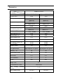
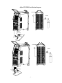
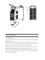
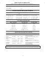
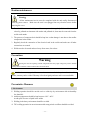
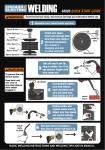
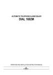
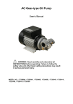
AHP WELDS USER MANUAL Alpha-TIG200X Contents 1. Safety ...................................................................................................................................... 2 2. About your AlphaTig 200X .................................................................................................. 3 3. Parameters ............................................................................................................................. 4 4. Panel Index ............................................................................................................................ 5 5. Setup Instructions ................................................................................................................. 6 6. Operating Instructions ....................................................................................................... 8 7. Polarity Recommendations ................................................................................................ ..8 8. Routine Maintenance .......................................................................................................... 11 9. Warranty .............................................................................................................................. 13 - 1 - Safety In welding and cutting processes protective measures should be taken to prevent injuries. For details refer to the safety protection guide for operation that meet the manufacturers’ requirements for accident prevention. Electrical Shock ·Grounding devices should be installed according to the applicable standards. ·Do not make contact with live parts or welding with exposed skin or with wet gloves or clothing. ·Make sure insulation exists between you and the ground and the work piece. ·Make sure that your operating position is in a safe state. Smoke ·Inhalation of smoke should be avoided. ·In arc welding a ventilator or exhaust should be used to avoid inhalation of welding gas. Arc light radiation ·Exposed skin should be covered when welding to avoid burns caused by exposure to the welding arc. A suitable welding helmet and filter lens to protect your eyes must be worn to avoid arc flash. ·Appropriate welding helmets or curtains should be used to protect spectators from injury. Fire ·Welding spark may lead to fire. Please make sure no combustibles exist near the welding area. Noise ·Protect your ears by wearing hearing protection. Warning This unit requires proper grounding!!! - 2 - About your AlphaTig 200X This welder adopts rectifiers designed with advanced inverter technology. The introduction of inverter TIG welders derives from inverter power theory and devices. The inverter TIG welding power uses high-power IGBTs to turn the working frequency of 50/60Hz to high frequency ( 20KHz or higher). Then voltage is reduced and current is regulated. A powerful DC power source can be produced by using the pulse width modulation (PWM) technology. The size and weight of inverter welders are reduced remarkably, while the efficiency is increased by 30% compared to older styled transformer based welders. This product is a multi-purpose unit composed of DC pulse TIG welder and AC pulse TIG welder, and DC Stick welder (MMA). This welder allows you the versatility of welding various types of metal including aluminum. Warning! This unit has a High Frequency start. This can interfere with some sensitive electronic components so care should be taken when in close proximity to such devises. - 3 - Parameters Model Alpha-TIG200X Parameter Power voltage Frequency (Hz) Rated Input Current (A) Output Current Regulation(A) No-load Voltage (V) Rated Working Voltage (V) 1phase AC110V±15% 1phase AC220V±15% 50/60 50/60 TIG:37.4 MMA:58.2 TIG:10-150 MMA:30-145 TIG:28 MMA:42.2 TIG:10-200 MMA:30-195 50-80 50-80 TIG:16 MMA:25.8 TIG:18 MMA:27.8 (-5+5)20-80% (-5+5)20-80% Pulse Time On(%) POST FLOW(S) 10-90 10-90 1-10 1-10 Pulse Frequency Hz 0.5-5 0.5-5 Base Value Current(A) 10-150 10-200 Arc Starting Current(A) 10-150 10-200 Arc End Amps Remote Control 10-150 10-200 Yes Yes high-frequency arc ignition high-frequency arc ignition Efficiency (%) 80 80 Load Duration Factor(%) 60 60 0.73 0.73 F F IP21 IP21 AC BALANCE Arc Ignition Mode Power Factor Class of Insulation IP code 67 Weight (lbs) 30 x12 x24.5 Overall Dimension(inches) Max welding thickness (inches) Pulse AMPS(PEAK) .5 ( 1/2") 10%-80% - 4 - 10%-80% Panel Index 1 Start Amp adjustment 11 Pulse switch ON/OFF 2 Amp meter 12 2T/4T switch 3 Peak Amp adjustment 13 AC/DC Function switch 4 Pulse Amps adjustment 14 TIG / MMA function switch 5 End Amp adjustment 15 Tig Torch Output 6 Post Flow adjustment 16 MMA ( stick) Output 7 Pulse time adjustment 8 Pulse frequency adjustment 9 Cleaning width adjustment (balance) 18 positive electrode output 10 Remote switch 19 Power switch 17 - 5 - Torch control switch socket/ Remote( pedal ) control socket Setup Instructions The welder is designed with a power voltage compensation. When power voltage fluctuates within a range of 15% of rated voltage, it will continue to operate. If a longer cable is used, we suggest using cable with a greater cross section in order to reduce line loss voltage. PLEASE NOTE: This Welder is designed to operate on Single Phase 110 and 220 Volt power sources. ( 110v 120v 220v 240v )with a plus or minus variant of 15% 1. Make sure that the vent of the welder is not covered or plugged to ensure the cooling fans can operate to their full potential . 2. Please ensure all fittings and connections from argon bottle to welder are secured correctly to prevent leaking. 3. When using a generator the unit should be grounded reliably with a grounding rod driven into the ground. 4. The Ground Clamp dinse connector is inserted into the work port on the welder and is turned clockwise to secure. The ground clamp is connected to a clean surface as close as possible to the welding operation to ensure a good ground. 5. Install the TIG torch copper nut connection (place supplied plastic sleeve on nut connection) from the torch cable connection to the TIG port, and tighten clockwise . 6. When the pedal switch is used connect the 5 pin plug of the pedal switch to the control outlet socket on the panel face. 7. For stick operation (MMA), select stick function on the TIG/MMA switch, make sure the Torch/Pedal switch is in the torch position. Connect the stick electrode holder to the Stick port (-) and the ground dinse is connected to the work port (+), these can be reversed for Stick function as the work port is positive and the stick port is negative. - 6 - Alpha-TIG200X Installation diagram Power supply Ar meter Gas cylinder Earth clamp Tig torch Work piece Power supply Ar meter Gas cylinder TIG wel din g to rch grou nd c lamp work piec e - 7 - Power supply Earth clamp Work piece Electrode holder Operating Instructions DC TIG welding 1. Turn the power switch ON, this is located on the back of the unit, the digital current meter and the cooling fans will turn on. 2. Open the valve on the gas cylinder and regulate the flow meter to the required value( 15 to 20 cfh). 3. If the AC/DC switch is on DC mode, and in tig function, welding such metals as stainless steel, iron and copper is possible. When in AC mode aluminum welding is possible 4. When torch/pedal switch is in the torch position the arc will be controlled by the torch switch. When the switch is in the pedal position the arc will be controlled by the pedal. 5. When the pulse switch is in the on position, you will need to set the pulse frequency for desired effect. 6. The pulse amps are a percentage of the main amps and this is to be set to what the required amps are for the type of material being welded. - 8 - 7. When you press the control button on the torch this will activate the solenoid valve and the high frequency in the machine, a sound will be heard with the argon gas flowing through the torch. If switched to pedal operation the pedal activates the flow and high frequency start. 8. The tungsten electrode of the welding torch is 2-4 mm from the work piece. 9. Using the Post flow control will protect the weld while it cools down by continuing the gas flow after the arc stops. 10. When 2T/4T switch is in the 2T position only the main amps will operate along with the post flow. In 4T position arc start amps and end amps will work. Do not use 4T function with the foot pedal. 11. When in 4T mode you press and release the switch an arc will start and continue to run until you press and release the switch again. AC TIG welding 1. If AC/DC switch is in AC mode, this process will weld aluminum and magnesium. All other metals require DC mode. 2. The AC balance (cleaning action) is used for oxidized aluminum. Care must be taken in choosing the correct tungsten size, as too much cleaning action can overheat the tungsten and melt it. DC STICK welding (SMAW) 1. For stick operation (MMA), select stick function on the TIG/MMA switch, make sure the Torch/Pedal switch is in the torch position. Connect the stick electrode holder to the Stick port (-) and the ground dinse is connected to the work port (+), these can be reversed for Stick function as the work port is positive and the stick port is negative. Warning: Inserting or pulling out any cable wire or plug while power is on will be hazardous and will damage the welder. - 9 - GENERAL POLARITY RECOMMENDATIONS* *Follow manufacturer of stick electrode for complete polarity recommendations TORCH POLARITY WORK POLARITY TIG (GTAW) - + STICK (SMAW) + - PROCESS TIG (GTAW) OPERATION GUIDE FOR STEEL (ALlIMINUM)* "As a general rule, set amperage using 1 amp for every .001" of metal thickness for aluminum. Less is required for DC. WELDING AMPS METAL THICKNESS TUNGSTEN DIA. Ar FLOW RATE (A) 1~3 mm/.040"~1/8" 1-3 mm/.040''-1/8'' 3~6 3-6 1-2 mm/.040"-3/32" 8-15 CFH /4-7lpm 40-80 (60-125) mm/1/8"-1/4'' 2-3 mm/3/32''-1/8'' 15-25 CFH/7-14lpm 80-200 (125-200) 6-10 mm/1/4"-3/8'' 150-200 (200-250) 3-6 mm/1/8''-1/4" 20+ CFH/10-15 lpm STICK (SMAW) OPERATION GUIDE METAL THICKNESS ELECTRODE SIZE WELDING AMPS < 1 mm/.040'' 1.5 mm/1/16'' 20-40 2 mm/.080" 2 mm/3/32" 40-50 3 mm/l/8" 3.2 mm/1/8'' 90-110 4-5 mm/3/16" 3.2-4 mm/1/8" 90-130 6-10 mm/1/4"-3/8" 4-5 mm/1/8"-5/32'' ll lf 130-200 , TUNGSTEN SELECTION GUIDE FOR AN INVERTER TYPE Pure PERCENT 100% Tungsten COLOR PROCESS RECOMMENDATION Green AC NOT RECOMMENDED! Do not use In an inverter. 2% Thorium Thoriated (slightly radioactive) Red AC/DC YES. Great for all purpose welding. Most eco nomica!. Ceriated 2% Ceria Orange AC/DC YES. Good for low amp use. Lanthanated 1.5% Lanthanum Gold AC/DC YES. Best alternative to 2% Thoriated. Tough performer. Lanthanated 2% Lanthanum Blue AC/DC YES. Slight advantage over 1.5% Lanthanated. Zirconiated 1% Zirconia Brown AC NOT RECOMMENDED! Do not use in an inverter. NOTE: Thoriated tungsten is slightly radioactive, but is commonly used in the US. Care should be used when grinding so as not to breath the dust. If you have concerns about Thoriated (red) tungsten, choose from Lanthanated or Ceriated tungsten. - 10 - Routine maintenance Warning: All the maintenance/service must be completed with the unit totally disconnected from any power source. Make sure the unit is not plugged into any electrical source before removing the cover. 1 Dust should be removed with dry and clean compressed air regularly. If the welder is used in a heavily polluted environment with smoke and polluted air, dust must be removed from the welder each month. 2 The pressure of compressed air should be kept low so that damage is not done to the smaller components in the welder. 3 Regularly check the connection of the electrical cord in the welder and make sure all other connections are secured. 4 Welder needs to be stored and used away from water, dirt or dust. Precautions Warning Opening the unit and exposing internal components that carry high voltage may lead to hazards and any direct or indirect contact could result in electrical shock. If within the warranty period the user carries out an unauthorized repair or alteration of the welder, warranty can be voided. Warranty is for the original purchaser and is non transferable. Preventative Measures 1. Environment 1)Welding operation should be carried out in a relatively dry environment with air humidity less than 90%. 2)Ambient temperature should be kept between -10C ~40C. Avoid spills of water or liquid in the welder 3)Welding in the dusty environment should be avoided. 4)TIG welding operation in an environment with strong winds or airflow should be avoided. - 11 - 2. Essentials for safety This welder has been equipped with over-voltage, over-current and overheat protection circuits. When the grid voltage, output current and machine temperature surpass the set standards, the machine will stop automatically. But excessive use (for example, when the voltage is too high) can still lead to the failure of the welder. Good ventilation! The vents on the welder must be kept clear of all obstructions to allow for good airflow through the unit. Keep at least 12 inches clear around the unit. No overload! Operators should remember that maximum welding amps relative to the duty cycle be observed at all times and welding amps should never exceed the maximum duty cycle. Over-cycling will shorten the life of the welder. No over-voltage! Power voltage is shown in the main performance parameter table. In general, the voltage auto-compensation circuit in the welder will ensure the welding current remain within the permissible range. If power voltage surpasses the permissible value, the welder will suffer damage. Operators need to be aware of this and take preventative measures. On the back of the welder there is a grounding screw with a grounding mark. The shell of the welder should be grounded securely with a grounding rod driven into the ground when using a with a clean power generator. Only a clean ‘Auto Voltage Regulated’ generator with a clean sine wave is recommended for this welder. If the welding machine exceeds the standard duty cycle, it will go into a protective state and shut down, which indicates it has exceeded the duty cycle. Excessive heating triggers the temperature control switch and shuts he welding process off. Under such circumstances do not turn off the power, let the cooling fan continue running to cool down the unit. When the temperature drops to the standard range, turn the welder off and turn it back on to continue welding. - 12- AHP WELDS 3 YEAR WARRANTY All new AHP welders, shall be warrantied to the original owner for a period to extend for 3 years from date of purchase against breakage, malfunction, or other unit failure resulting from manufacture defect. The faulty unit will either be repaired or an exchange will be made for a new or factory reconditioned unit at AHP Welds discretion. The customer must contact the technical support team to review unit failure so that the warranty claim can be established. Items such as electrodes, contact tips, nozzles, cups, shields, liners etc, considered to be consumable items, are NOT covered under warranty. Torches, foot pedals and spool guns are warrantied for a period of 6 months. Additionally, certain items such as torches, foot pedals and easily serviced parts may be individually exchanged without returning the entire unit assembly should a failure with these items occur, at AHP Welds discretion. AHP Welds will not be responsible for time/contract loss from unit failure, damages occurring from improper or unskilled operation, damages resulting from improper maintenance, improper wiring, poor quality power sources, abuse or neglect. Nor will AHP assume responsibility for the customer's failure to heed/read safety instructions, to read and understand operator's manual, obey occupational laws or to ensure the unit's safe operation complies with state or local laws, personal injury arising from the inherent risks involved with welding, including burns, electric shock or death. Warranty extends only to the machine, its accessories and parts contained inside as stated above. No other warranty is expressed or implied. For complete warranty please visit http://www.ahpwelds.com/return_warranty.php to register you unit for warranty please visit http://www.ahpwelds.com/product_registration.php [email protected] 925-271-2021 - 13 -