1
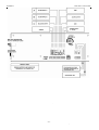
AUTOMATIC TELEPHONE ALARM DIALER
DIAL 1602M
OPERATION AND INSTALLATION INSTRUCTION MANUAL
ROGER s.c.
DIAL 1602 v1.0 25/11/1999
TABLE OF CONTENTS
POWER SUPPLY
TABLE OF CONTENTS................................................................ 1
INTRODUCTION.......................................................................... 1
OVERVOLTAGE PROTECTION .................................................. 1
INSTALLATION OF THE DIALER ................................................ 1
POWER SUPPLY......................................................................... 1
DIALER MEMORY KEEP-UP WITH A BATTERY......................... 1
STRUCTURE OF THE CONTROL INPUTS A, B and C ............... 1
CONNECTION OF THE ALARM LINES A AND B ........................ 1
CONNECTION OF THE BLOCKING LINE.................................... 1
CONNECTION OF THE TELEPHONE LINE ................................ 1
CONNECTION OF THE PGM OUTPUT ....................................... 2
DIALER CODES........................................................................... 2
INSTALLER CODE ................................................................ 2
USER CODE.......................................................................... 2
CONFIGURATION CODE ...................................................... 2
DURESS CODE..................................................................... 2
CODE ENTRY \ ALARM RESET .................................................. 2
DIALER TESTING ........................................................................ 2
SWITCHING ON THE POWER SUPPLY ..................................... 2
DIALER OPERATING MODES..................................................... 2
PROGRAMMING MODE .............................................................. 2
[1] Programming the numbers ................................................ 2
[2] Recording/Playing of Alarm Announcement....................... 2
[3] Installer/User Code............................................................ 3
[4] Programming of the date and clock ................................... 3
[5] Dialer configuration............................................................ 3
[6] Read-out of the Event List ................................................. 3
[0] Exit from the programming mode....................................... 3
BLOCKING MODE ....................................................................... 4
READY MODE ............................................................................. 4
ALARM MODE ............................................................................. 4
Single message dialer. ........................................................... 4
Double message dialer........................................................... 4
DURESS ALARM ......................................................................... 4
PAUSE MODE ............................................................................. 4
Single message dialer ............................................................ 4
Double message dialer........................................................... 4
TELEPHONE LINE LISTENING ................................................... 4
EXTERNAL CALL ANSWERING FUNCTION............................... 4
TECHNICAL SPECIFICATION ..................................................... 4
DRAWINGS.................................................................................. 4
The dialer requires DC power supply from 11 do 15V. A loss of
power supply results in resetting the dialer time and date, however,
the other information stored in the dialer memory is not lost. When
the allowable voltage (15V) is exceeded or the voltage polarity is
wrong, it may cause, besides burning the F1 fuse, damage to the
dialer.
DIALER MEMORY KEEPKEEP-UP WITH A BATTERY
The dialer is originally equipped with a 3V/120mAh battery, which
guarantees keeping up the memory for minimum 60 days in case
of a power supply loss. The memory stores the alarm telephone
numbers, alarm messages, history of events and dialer
configuration parameters. A power supply loss results only in
resetting the time and date. A lack or low battery (voltage lower
than 2.7V) at a power supply loss results in resetting the dialer
memory and restoration of the default parameters of dialer
configuration. The condition of the battery should be checked after
each loss of power supply but not less frequently than once per
year. If you want to reset the dialer programming and restore its
default values of codes and configuration parameters (which can
occur when you have forgotten the currently programmed access
codes), you should interrupt the battery supply of the dialer RAM
memory by inserting an insulation material strap under the battery
holding plate and switching off the power supply for 1 minute. If
after switching the power supply on again, the dialer displays the
message DIALER PROGRAMMING RESET, you should connect
the battery supplying the RAM memory and program the dialer. In
case of difficulties with resetting the RAM memory in the described
above method, you should repeat all the steps and additionally
close the JP7 jumper contacts for a moment with a metal object
after switching off the power supply and disconnecting the battery.
STRUCTURE OF THE CONTROL INPUTS A, B and C
Activation of the T1 transistor, when the line is programmed as
NO, results in a release of the line. In case the line is programmed
as NC, deactivation of the T1 transistor results in a release of the
line. The blocking line C is permanently configured as a NO type
line.
CONNECTION OF THE ALARM LINES A AND B
INTRODUCTION
Depending on the configuration of the alarm line (NO or NC),
different systems of the alarm line release are used. The alarm
criterion on the alarm input can be performed by giving the suitable
voltage or with a non-potential contact with a serial resistor.
Please note that the presented systems of the voltage release of
the line apply when the dialer and the releasing device have a
shared power supply minus (ground) cable and the use of the
control output with a signaling device is only an example of a
solution, the alarm input can be controlled from any other source of
power supply.
The alarm dialer transmits via telephone an announcement on an
occurrence of an alarm at the supervised facility. The DIAL 1602
can be configured as a dialer with one alarm message and ten
alarm telephone numbers or two messages and five alarm
numbers designated for each of the messages. The latter solution
allows for distinguishing the alarm type (e.g. burglary and fire) and
commencing a notification action suitable for the type of danger.
The DIAL1602 can be also used as a two-zone alarm exchange,
since it is provided with an alarm signaling output, an input to
connect a coder and the complete range of programming of delays
for an entry and exit from the facility, alarm times, etc.
CONNECTION OF THE BLOCKING L
LINE
INE
OVERVOLTAGE PROTECTION
The C blocking line is controlled in the identical manner as the
alarm line, programmed as NO. Programming the blocking line as
NC is not possible.
The DIAL 1602 is designed in such a manner that it is resistant to
overvoltage occurring in a telephone line up to 2kV. If a telephone
line is not provided with an efficient overvoltage and lightning
protection system, an atmospheric discharge may cause an
overvoltage in it, which could be much higher than 2kV. A repair
of damage caused by atmospheric discharges is not included in
the warranty. When there is danger of such damage, it is
recommended to install a special protective system connected in
between the dialer and telephone line.
CONNECTION OF THE TELEPHONE LINE
The telephone line wires are connected to the terminals no. 9 and
10, the telephone to the terminals no. 7 and 8. This method of
connection provides that during an alarm action, the telephone is
disconnected from the telephone line and therefore it is not
possible to block the telephone line by the wrong hang-up of the
speaker. The telephone can be also connected parallel with the
dialer, i.e. to the terminals no. 9 and 10 but in this case, in older
type telephones, you can hear the dialing tones generated by the
dialer and it will be also possible to block the telephone line, thus
the dialer, by the wrong speaker hang-up.
INSTALLATION OF THE DIALER
Electronic elements used in the device are sensitive to static
potentials. The elements cannot be touched or handled with any
tools. The dialer should be installed in an enclosed room, far from
any sources of moisture and heat. Power supply should be
connected after completion of all electrical connections.
-1-
ROGER s.c.
DIAL 1602 v1.0 25/11/1999
CONNECTION OF THE PGM OUTPUT
Note !
The captions in the following part of the text in "[ ]" brackets are
also messages which are displayed on the dialer display at various
stages of its use and operation.
test the RAM memory. If the dialer programming has been lost, the
[First start of dialer] message is displayed, and then [DIALER
PROGRAMMING LOST !] / [ ENTER DEFAULT CODE]. Then
you should press the [#] key and after message [Enter code] is
displayed, you should enter the default installer code, i.e. 1234;
end the code entry with the [#] key. The dialer will go to the
programming code. If after switching on, the power supply the
RAM test is successful, the message [Dialer Restart] will be
displayed and the device will switch to the ready mode. The
pulsing display signalizes a necessity of programming the time and
date. After a restart, despite resetting the time and date, the RAM
memory is not reset and the dialer monitors the alarm inputs and is
ready to handle the alarm in the A or B line.
DIALER CODES
DIALER OPERATING MODES
The dialer has four codes. Each of the codes, except for the
duress code, can include up to 6 digits. A code can be
programmed as a blank one, then after a request [Enter code] you
should only press the [#] key. The codes are also used for
changing various operation modes of the dialer (see "Schematic of
changing the modes").
The DIAL 1602 can operate in one of the following operating
modes:
- programming mode
- blocking mode
- ready mode
- alarm mode
- pause mode
The PGM output signalizes switching the dialer into the condition
of a loud alarm. It can also signalize switching into the ready mode
(see the dialer configuration). It is an "open collector" type output
and can be added with an additional relay to activate signaling
devices. The maximum current at the output should not exceed
500 mA.
INSTALLER CODE
The default setting is 1234. It is used to exit the current operation
mode (together with the alarm mode) and to enter the
programming mode.
PROGRAMMING MODE
You can go to the programming mode from any mode by entering
the installer code.
[#] – starts the code entry
[Installer code][#]
USER CODE
The default setting is 1111. It is used to interrupt the alarm action,
enter or exit the ready mode.
You can enter one of the 6 programming procedures by selection
of the suitable key (1..6). You can exit any of the procedures by a
single or double use of the [#] key.
If you change the dialer configuration from a single message dialer
to a double message dialer or inversely during the dialer
programming, you must enter the configuration procedure no. [5]
and select the proper option prior to programming the telephone
numbers and pre-recording the announcement(s).
CONFIGURATION CODE
The default setting is 1234. It is used to enter the dialer
configuration procedure in the programming mode.
DURESS CODE
Entering the sequence of characters [*][digit][*] in the blocking or
ready mode, results in activation of the duress alarm. The digit
between the [*] symbols is preset as [0] and can be reprogrammed
during the dialer configuration procedure.
[1] Programming the numbers
In case of a single message dialer, you can program up to 10
telephone numbers (maximum a 16-digit number) marked from L1
to L10 in the list. In case of a double message dialer, you can
program up to 5 numbers in the list "A" (from A1 to A5) and up to
5 numbers in the list "B" (from B1 to B5). You use the [*] key to go
to the next number in the list. Any numerical key resets the old
number and starts a stand-by mode of waiting for the new number
digits.
You end the number entry with the [*] key. The [#] key used during
entering the telephone number digits enters the character "P"
(pause). The character makes the system wait for a dial tone. If the
signal is recognized, the device starts dialing the next digits of the
number. If the dialer does not recognize the continuous signal
within 4 seconds, it unconditionally starts dialing the next digits of
the telephone number. You can skip the telephone number
programming function when getting to the last number in the list
(L10 or B5) or earlier by pressing [#]. The character P in the
telephone number is used when dialing long distance connections
(e.g. 0P22340967), when you expect a long time of waiting for an
telephone exchange tone or if for any other reasons you have to
force an interruption in dialing (which is often required for older
type subscriber telephone exchanges).
CODE ENTRY \ ALARM RESET
If you want to enter the user or installer code, you should stop the
current mode with the [#] key. The system will display the following
message [Enter code
_ ], then you should enter the correct
installer or user code and end it with [#]. The program allows three
attempts of entering the code. After the third unsuccessful attempt,
the program blocks the keypad for 3 minutes and records the
[Wrong code entered] message in the event list. If within 30
seconds from the moment of displaying the [Enter code] message
the code is not entered, the attempt will be qualified as the wrong
code. You can interrupt the alarm action or a pause after it by
entering the installer or user code. The alarm action can be also
interrupted by releasing the C blocking input for a time longer than
200 ms.
DIALER TESTING
Each time the dialer enters the ready mode, it previously tests the
telephone line, A and B alarm inputs and microprocessor system.
The telephone line tests check if a telephone exchange tone
exists. The alarm line test checks if there are no alarm tones in the
lines during the test. The microprocessor system test verifies its
correct operation. The test end is signalized with displaying the
[Negative tests N] message, where the number N stands for the
quantity of negative tests. The test results are recorded in the list
of events.
[2] Recording/Playing of Alarm Announcement
Note !
After each time a new announcement is recorded, you should
listen to it using the headphone output to make sure the
announcement is readable and, if needed, repeat recording.
You should record alarm announcement(s) by speaking to the
built-in microphone from a distance of about 20cm. The start of
recording is signalized with an acoustic tone. The recording is
ended automatically after the available recording time has elapsed
(14s for a single message dialer or 7s for a double message
dialer). The duration of an announcement can be shortened by
pressing [#]. You can exit the Record/Play procedure with the [#]
key.
SWITCHING ON THE POWER SUPPLY
After the power supply has been switched on, the dialer checks the
value of the power supply voltage and if it is too low, the [Low
power supply voltage] message is displayed. Until its value
reaches the suitable level, the dialer will not go to the next steps of
the start procedure. When the power supply voltage is higher than
9.5V, the dialer will display the [Roger DIAL1602] message and
-2-
ROGER s.c.
DIAL 1602 v1.0 25/11/1999
[3] Installer/User Code
To reprogram the code, you should first determine which code will
be changed ([0] or [1] key) and then, by pressing any numeric key,
reset the old code and enter the new one ending it with [#]. If you
press [#] again, you will exit the code setting procedure.
alarm line blocking from the moment the notification action was
stopped, which was initiated in this line. It is shared by both alarm
inputs. In case of a single message dialer, both alarm lines are
blocked for the pause time regardless in which one the alarm was
initiated (min.000min. max 255min.).
[Duress code *0*]
The digit between the * characters is programmed.
[Configuration code 1234]
By pressing any numerical key, you reset the old code and then
enter the new code. You end the code entry by pressing the [#]
key.
[4] Programming of the date and clock
By using [*], you can move the pulsing cursor at the position which
is to be programmed. The first two digits specify the day of a
month, the next two – the month, the remaining ones – the hour
and minutes, you finish setting the date and time by pressing [#].
[5] Dialer configuration
You enter the dialer configuration procedure after you have
previously entered the valid configuration code. The dialer
configuration is performed by selecting the suitable options, which
are presented on the display. The pulsing cursor indicates the
currently set option. By pressing [*], you go to the next elements of
the configuration procedure. By using the [#] key at any moment,
you enter the completed changes to the memory and exit the
configuration. You change the current option by selecting [0] or [1].
When setting the times (delay, alarm and pause), [0] deducts one
unit and [1] adds one unit to the current value.
If you change the single message option to the double message or
inversely, the dialer notifies about resetting the previously
programmed announcement numbers and about a necessity of
their reprogramming, after the exit from the configuration
procedure.
[6] Read-out of the Event List
The program remembers the last 100 events regarding the alarm
action and keypad operation. The description of an event is
arranged so that the event date and time are displayed first and
than its description is displayed. The event list starts with the last
event. You can read out the event history using the following
navigation keys:
[2] displays an earlier event
[8] displays a later event
[4] moves the event description to the left
[6] moves the event description to the right
[5] returns the event description to its beginning
You can also go to a later event by using the [*] key. You exit the
event history read-out by pressing [#].
Note !
"[ ]" brackets contain the text of the messages displayed by the
dialer, whereas the default (manufacturer's) values are put in bold.
Dialer configuring procedure.
[Alarm message number: 0-1 messages 1-2 messages]
Option selection; 1 message 14s and 10 alarm telephone numbers
in the L1-L10 list or 2 messages 7s each and two telephone
number lists: A1-A5/B1-B5, five alarm numbers each.
TYPE OF EVENT
[Ready mode]
[Blocking mode]
[Alarm A]
[Alarm B]
[Pause in alarm NN minutes]
Note !
If you change the dialer configuration from a single message to a
double message dialer or inversely, the previously programmed
telephone numbers and pre-recorded alarm announcements will
be reset.
[MN notification: O.K.]
[Input A activation time: 0-200ms 1-2sec.]
[Input B activation time: 0-200ms 1-2sec.]
The minimum alarm duration time in the line A(B) required for
initialization of the alarm action.
[Line type A : 0-NC 1-NO]
[Line type B : 0-NC 1-NO]
Alarm line type NO/NC
[Line A delay: 000s]
[Line B delay: 000s]
An alarm line delay is the time from the moment of an alarm line
release to the moment when the dialer enters the alarm condition.
(min.000s max.255s).
[Silent alarm in line A: 0-NO 1-YES]
[Silent alarm in line B: 0-NO 1-YES]
When an alarm line is set as silent, the PGM output is not
activated during an alarm and the dialer only performs the action of
telephone notification.
[Output delay 000s]
This is a delay prior to switching to the ready mode (min.000s max
255s).
[Ready mode activation confirmation: 0-NO 1-YES]
The function activates the PGM output for 0.3s at the moment the
dialer switches to the ready mode.
[Blocking mode allowed: 0-NO 1-YES]
When the blocking mode is allowed, the dialer can be used as a
double line alarm exchange (see BLOCKING MODE).
[Should dialer answer external calls: 0-NO 1-YES]
see EXTERNAL CALL ANSWER FUNCTION
[Telephone exchange type: 0-PULSE 1-DTMF]
It specifies the method of dialing when cooperating with a
telephone exchange.
[PGM output alarm time PGM 000s]
It specifies the duration of PGM output activation from the moment
a loud alarm is switched on (min.000s max. 255s).
[Pause between alarms 000min.]
In case of a double message dialer, it specifies the duration of
[Installer code entered]
[User code entered]
[Configuration code entered]
[Wrong code entered]
[Negative dialer test]
[Dialer test O.K.]
[MN telephone
programming]
[Dial restarted]
[DIALER SWITCHED OFF]
[Time setting]
[User code change]
[Installer code change]
[Configuration change !]
[Input C alarm interrupted]
INTERPRETATION
the dialer is in the ready mode
the dialer is in the blocking mode
an alarm in the line A
an alarm in the line B
the dialer is in the NN minutes
pause mode
a connection with the number N in
the list M was made
the correct installer code was
entered
the correct user code was entered
the correct configuration code was
entered
despite three attempts the correct
code was not entered
a dialer test when switching to the
ready mode found errors
a dialer test when switching to the
ready mode did not find errors
the number N in the list M was
programmed
the dialer power supply was
switched on, RAM memory test
O.K.
power supply was lost
the date and clock were
programmed
the user code was reprogrammed
the installer code was
reprogrammed
the dialer configuration parameters
were changed
the alarm action was interrupted by
releasing the blocking input C
[0] Exit from the programming mode
Prior to an exit from the programming mode, the system checks if
any telephone numbers and recorded announcements are stored
in the dialer memory. If there are not any, the dialer displays the
appropriate message. The system automatically exits the
programming mode, if you do not press any key for 3 minutes.
From the programming mode the dialer goes to the blocking mode
-3-
ROGER s.c.
DIAL 1602 v1.0 25/11/1999
Double message dialer
When the notification procedure is completed, the dialer switches
to the pause during which it blocks the alarm input from which the
alarm was initiated, monitors the other alarm input and is ready to
start the alarm action from the line, provided it is initiated. During
the notification action both alarm inputs are blocked. After the
pause time has elapsed, the system returns to the ready mode and
stops blocking both alarm inputs.
(if it is allowed) or direct to the ready mode. See the schematic of
changing the dialer modes.
BLOCKING MODE
The blocking mode, if allowed in the configuration procedure,
enables a use of the dialer as a double line alarm panel. In the
blocking mode the dialer ignores the alarm condition in the lines A
and B. However, if such a condition occurs, the dialer displays the
name of the line in which the alarm was initiated. You switch to the
blocking mode (if it is allowed) from the alarm mode, pause mode
or ready mode by entering the user code or by going to the
programming mode (see the schematic of changing the dialer
modes).
TELEPHONE LINE LISTENING
Using the headphone output, in addition to listening to the alarm
announcement, you can listen to the notifications, since the
telephone line tones are retransmitted to the headphone output.
READY MODE
EXTERNAL CALL ANSWERING FUNCTION
In this mode the program monitors the alarm inputs. When an
alarm is recognized in an alarm line, the system starts counting of
the time delay for the specific line and then it goes to the alarm
mode. Each time the ready mode is activated, which is performed
after entering the user code, it is preceded by performing the
system testing procedure and counting the output delay. When the
blocking line C is released in the ready mode, the alarm inputs A
and B are blocked. The lines A and B remain blocked as long as
the line C remains released. The release condition of the blocking
line C is signalized by displaying the letter C on the dialer display.
The function allows you to obtain remote information if there was
an alarm activated at the facility where the dialer is installed. You
can get such information by dialing the dialer telephone number. In
this function the dialer, being in the ready mode, after recognition
of 8 call tones, connects into the telephone line and transmits an
acoustic signal for 20s. If no alarm occurred at the facility from the
time the dialer went to the ready mode, the transmitted acoustic
signal is a two-second acoustic tone, repeated cyclically. If there
was an alarm at the facility, which was not reset, the dialer
transmits a signal, which is modulated in the identical way as the
signal preceding the alarm announcement.
ALARM MODE
TECHNICAL SPECIFICATION
Single message dialer.
After recognition of the alarm condition in the line A (B), the dialer
begins counting the A (B) input delay. If you do not enter the
correct user or installer code during the counting of the input delay,
the dialer will start dialing the numbers in the list L1..L10, in the
sequence the numbers were put in the list. After making the
connection, the dialer transmits the alarm tone and announcement
five times, then it goes to the next number. The described action is
repeated twice. During the alarm action any signals in the alarm
inputs A and B are ignored.
Power supply
Input current in ready mode
Dimensions L x W x H
Temperature range
DRAWINGS
Double message dialer
In this case the alarm mode initialization algorithm is identical as
for the single message dialer. The difference is that if an alarm
was activated in the input A, the system dials the numbers from
the list A1..A5 and the announcement A is transmitted. If an alarm
was activated in the line B, the system dials the numbers from the
list B1..B5 and the announcement B is transmitted. During the
alarm action the dialer displays two letters informing about the type
of the current alarm action and the name of the alarm input, which
initiated the alarm, to the right from the caption Ready.
Alarm types:
AG – loud alarm
AC – silent alarm
AN – duress alarm
(activates the PGM output)
(does not activate the PGM output)
(silent alarm in the line A)
DURESS ALARM
You can initiate the duress alarm in the Blocking or Ready mode
by entering the duress code:
[*] digit [*]
Regardless the line A programming as silent or loud, or the dialer
configuration as single message or double message, the duress
alarm is performed silently and corresponds the alarm initialization
in the line A. Following the completion of the duress alarm, the
dialer goes direct to the Ready mode.
PAUSE MODE
Single message dialer
When the notification procedure is completed, the dialer switches
to the pause during which it blocks both alarm inputs. After the
pause time has elapsed, the system returns to the ready mode and
stops blocking both alarm inputs.
-4-
11V..15V
typically 45mA
215 X 95 X 27
0..50 C˚
ROGER s.c.
DIAL 1602 v1.0 25/11/1999
-5-
ROGER s.c.
DIAL 1602 v1.0 25/11/1999
Schematic of changing the DIAL1602 dialer operating modes.
NOTE !
Pause after the duress alarm equals 0 minutes.
(INSTAL. CODE-Installer code; USR. CODE-User Code)
-6-