1
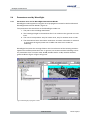
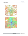
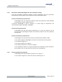
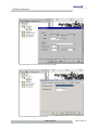
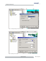
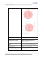
User Manual
For Forsk Atoll
<1.5>
REF: RP/WAVECALL/06-2001N01/OG
Abstract
This document describes the installation of the propagation model WaveSight
COM component of Forsk Atoll engineering tool, and provides technical
information about the data and parameters required by WaveSight.
WaveSight User Manual Atoll
Company Information
Address
Lausanne
Wavecall SA
Science Park of the
Swiss Institute of Technology
PSE-B / EPFL
1015 Lausanne
Phone +41 21 693 84 05
Fax
+41 21 693 84 06
Amsterdam
Wavecall BV
NZ Voorburgwal 66/III
1012 SC Amsterdam / NL
Phone +31 20 320 8302
Fax
+31 20 528 7363
Contact
Dr. Karim Rizk, CEO
Email
Web
[email protected]
http://www.wavecall.com
Document History
Version
Revision
Date
1.0
Odeh Ghawi
June, 25 2001
1.1
Odeh Ghawi
August, 14,2001
1.2
Odeh Ghawi
October 24, 2001
1.3
Odeh Ghawi
October 31, 2001
1.4
Odeh Ghawi
October 31, 2002
1.5
Odeh Ghawi
January 30, 2004
Acknowledgements
© 2002 Wavecall SA
Feb-04 - Page 2/2
WaveSight User Manual Atoll
Contents
1.
INTRODUCTION
5
2.
INSTALLATION AND CONFIGURATION
6
2.1
Version
6
2.2
Prerequisites
6
2.3
Installation
6
2.3.1
6
2.4
Installation procedure
Parameters used by WaveSight
2.4.1
8
Parameters to be set for WaveSight deterministic
Model
2.5
3.
4.
8
2.4.2
Parameters read by WaveSight from the transmitters setting
11
2.4.3
From the predictions properties
11
Buildings data
15
2.5.1
Configuring the data
15
2.5.2
Data requirements
15
2.5.3
Data format
17
Vector Index File
18
Vector Attributes File
19
2.6
Terrain data
19
2.7
Running WaveSight
19
2.7.1
20
WaveSight progress window
WAVESIGHT RAY TRACING MODEL
21
3.1
Background
21
3.2
WaveSight feature overview
21
3.3
Accuracy
21
3.4
Computing time
22
FREQUENTLY ASKED QUESTIONS
23
4.1
Parameters
23
4.2
Environment
24
4.3
Algorithm optimization, accuracy
25
4.4
Terrain, Buildings
25
4.5
Indoor
26
4.6
Running
27
5.
APPENDIX I (WAVESIGHT ERROR MESSAGES)
28
6.
APPENDIX II (WAVESIGHT WARNING MESSAGES)
30
© 2002 Wavecall SA
Feb-04 - Page 3/3
WaveSight User Manual Atoll
7.
BIBLIOGRAPHY
31
© 2002 Wavecall SA
Feb-04 - Page 4/4
WaveSight User Manual Atoll
1.
Introduction
This document provides information about using WaveSight prediction model inside
Forsk Atoll.
The following chapters illustrate step by step how to set the parameters and data that
WaveSight uses from Atoll setting.
Chapter 2 explains how to install WaveSight and configure all the parameters that
WaveSight needs, including the format of buildings and terrain data supported by
WaveSight, and gives a complete picture about the WaveSight during running time,
which include all error and warning messages that could appear.
Chapter 3 gives a brief description about WaveSight as a ray-tracing model including
the basic principle, the radio performances and running time.
Chapter 4 gives a list of all Frequently Asked Questions by clients or partners about
WaveSight model.
© 2002 Wavecall SA
Feb-04 - Page 5/5
WaveSight User Manual Atoll
2.
Installation and configuration
2.1
Version
Component
Version information
WaveSight
algorithm
3.2.0.ATOLL_COMPTIBLE
Interface COM
component
2.10
This release is licensed using Wavecall's node-locked, time-bombed licensing scheme.
It is necessary to obtain a license string from Wavecall to successfully run the
software.
2.2
Prerequisites
1. Required platform:
Pentium > 200 MHz.
30 Mbytes of free disk space for WaveSight.
RAM > 128 Mbyte (allows a prediction radius of 2 Km), 512 Mbytes is
recommended.
Windows NT.
2. Forsk Atoll 1.6 or higher.
3. WaveSight could use up to 200MB (for a prediction area of 10X10 km) of hard disc.
Make sure that they are available at the partition where Wavecall is installed.
2.3
Installation
2.3.1
Installation procedure
On Windows NT, log in with an account having administrator privileges.
Make sure that DLL files are visible in the Windows Explorer. Select "Display all
Files" in the Options dialog Figure 1.
Expand the distribution archive into a temporary directory and run Setup.exe.
© 2002 Wavecall SA
Feb-04 - Page 6/6
WaveSight User Manual Atoll
Figure 1 Make all DLL files visible (window option)
After a welcome and a license agreement screen, the following window appears Figure 2.
Figure 2 License key window.
© 2002 Wavecall SA
Feb-04 - Page 7/7
WaveSight User Manual Atoll
Note:
To obtain the license key, please send the shown Host ID to Wavecall to obtain the
key.
The license key is a string of the form:
74DE5B70F23052EB333E958439362EA16D3EAE6435A9630FD3391, which needs to be
entered into the License key field.
A message should appear indicating that the COM component has been
successfully registered.
You are now ready to configure and use WaveSight inside Atoll.
© 2002 Wavecall SA
Feb-04 - Page 8/8
WaveSight User Manual Atoll
2.4
Parameters used by WaveSight
2.4.1
Parameters to be set for WaveSight deterministic Model.
WaveSight model appears among the list of propagations model in Atoll as Wavecall
WaveSight deterministic Model. (Figure 3)
The parameters that should be set for WaveSight model are:
1. The path to the buildings data folder.
2. The buildings Height in the attribute file if it is relative to the ground or to sea
level.
3. The area of computation: only for indoor area, only for outdoor area or both.
4. The Attenuation factor should be used when an indoor calculation is selected.
It represents the signal power loss in dBm and used in the model as
following:
WaveSight Computes the average field on the circumference of the building and then
applies the constant penetration loss. In general, we recommend the following values
for penetration loss: concrete walls: 20 dB, wooden walls: 16 dB, metallic shielded
glass: 25 dB see Figure 4 Figure 5 Figure 6.
Figure 3 WaveSight propagation model
© 2002 Wavecall SA
Feb-04 - Page 9/9
WaveSight User Manual Atoll
Figure 4 only indoor predictions
Figure 5 only outdoor predictions.
© 2002 Wavecall SA
Feb-04 - Page 10/10
WaveSight User Manual Atoll
Figure 6 Both (indoor and outdoor)
© 2002 Wavecall SA
Feb-04 - Page 11/11
WaveSight User Manual Atoll
2.4.2
Parameters read by WaveSight from the transmitters setting
From the transmitters database window of Atoll, WaveSight uses the parameters
shown below as they appear in the properties of the transmitters folder.
From the transmitters properties info:
WaveSight uses the frequency defined under the frequencies option Modify,
the frequency is given in MHz, Figure 7
In General, WaveSight is able to operate in a wide range of frequencies; the
recommended range is 500 MHz - 5000 MHz.
From the site properties info:
WaveSight uses the site location coordinate X, Y. If the cell location is not at
the same place, WaveSight considers the relative position in the cell properties,
see Figure 8.
From the transmitter properties info:
WaveSight uses the equivalent isotropic radiated power (EIRP) in dBm.
The antenna pattern, WaveSight uses both horizontal and vertical pattern.
The antenna height in m.
The antenna down tilt in degree.
The antenna direction or azimuth in degree.
The calculation radius in m Figure 10 (Note: the prediction model selected in
this window is the one that would be used for the propagation).
2.4.3
From the predictions properties:
WaveSight uses the calculation resolution in m Figure 11.
The receiver height in m, from the receiver option Figure 12.
© 2002 Wavecall SA
Feb-04 - Page 12/12
WaveSight User Manual Atoll
Figure 7 frequency used by WaveSight
Figure 8 Setting base station location used by WaveSight
© 2002 Wavecall SA
Feb-04 - Page 13/13
WaveSight User Manual Atoll
Figure 9 Setting base station parameters used by WaveSight
Figure 10 Setting WaveSight calculation radius
© 2002 Wavecall SA
Feb-04 - Page 14/14
WaveSight User Manual Atoll
Figure 11 Setting WaveSight prediction resolution.
Figure 12 Setting receiver height
© 2002 Wavecall SA
Feb-04 - Page 15/15
WaveSight User Manual Atoll
2.5
Buildings data
2.5.1
Configuring the data
The Buildings vector data used by WaveSight should be added to Atoll project as
mentioned in paragraph 2.4.1 Figure 3.
Building vector data is stored in ASCII format and requires three types of input file - a
vector data file, an attribute file and an index file. The index file is similar to a normal
vector index file. Each line describes: a vector data file name, an attribute file name,
Easting Northing co-ordinates representing a bounding box around that feature and
the feature name itself.
2.5.2
Data requirements
The buildings data used by WaveSight model the buildings footprint and the buildings
height. The buildings data should comply with the following requirements:
Requirement
Explanation
Identical polygons are not
accepted
The dataset should not repeat the same
building.
Polygons must be closed. The first
and the last point in each polygon
must be identical.
Open "polygons" are not accepted:
At least 3 vertices per polygon
The dataset should not contain one or two
coordinate "buildings".
One vertex must belong to
exactly two walls
This requirement means that
"Spikes" (the building outline contains a
vertex which comes back on a previous
vertex) are not permitted in the outline:
© 2002 Wavecall SA
Feb-04 - Page 16/16
WaveSight User Manual Atoll
"8-shaped buildings" (the building outline
actually contains two buildings, touching
each other at one coordinate) are not
permitted:
Each two walls can only intersect
if they are successive walls
belongings to the same polygons.
In such a case the intersection
forms the vertex.
This means that
Self-intersecting polygons are not allowed.
© 2002 Wavecall SA
Feb-04 - Page 17/17
WaveSight User Manual Atoll
Overlapping polygons are not allowed:
All heights must be above local
ground.
It is not permitted to model "holes" as
buildings below the terrain height level.
An accuracy 1 m in building
corner position is required
The paper [2] contains a discussion of the
influence of the database accuracy on
prediction results. It is available on
Wavecall's web site.
There should not be repeated
vertices.
This restriction applies to the versions
before2.2.19 of the WaveSight algorithm.
The index file must contain the
string "building"
Only the entries containing the "building"
string are read by WaveSight.
It is important to set the frame
coordinates correctly in the file
index.txt
WaveSight only reads the buildings inside
these coordinates.
© 2002 Wavecall SA
Feb-04 - Page 18/18
WaveSight User Manual Atoll
2.5.3
Data format
An example of the buildings format, with all conditions as indicated above, is shown
below:
Vector file
Header Record
Easting
Northing
Easting
Northing
Easting
Northing
Easting
Northing
Easting
Northing
Header Record
Easting
Northing
Easting
Northing
Easting
Northing
The final row is terminated by a carriage return.
The format of the header record is as follows:
Field
Position Description
1
1-5
Record Identifier (used to identify building segment in attributes
file)
2
6-15
Blanks
3
16-47
32 Character description (not used, same as feature name field in
index file entry)
4
48-50
Blanks
5
51-55
Record Count
00001
buildings
00005
725777.00 5031472.00
725775.00 5031468.00
725778.00 5031467.00
725780.00 5031471.00
725777.00 5031472.00
00002
buildings
00005
725783.00 5031472.00
725781.00 5031468.00
........
The final row is terminated by a carriage return.
© 2002 Wavecall SA
Feb-04 - Page 19/19
WaveSight User Manual Atoll
Vector Index File
An ASCII text file called index.txt contains positional information about vector file.
This file must be in the same directory as the vector data.
Each row contains the following variables separated by a space:
Field
Description
Data filename
Filename of vector data file
Attribute filename
Filename of building attributes (heights) file
Eastmin
Minimum Easting value (metres)
Eastmax
Maximum Easting value (metres)
Northmin
Minimum Northing value (metres)
Northmax
Maximum Northing value (metres)
Feature Name
Name of the feature stored in the vector data file, for
WaveSight this name should contain a string called
“building” included in the feature name.
For example:
buildings_vec.txt buildings_atr.txt 1627764 1630022 6579401 6582574 buildings
The final row is terminated by a carriage return.
Vector Attributes File
An ASCII text file, named in the index file contains height information about the
building segments contained in the vector data file.
Each row contains a record, as follows:
Field
Position
Description
1
1-5
2
6
Delimiter <space>
3
7-19
12 Character vector segment description (not used)
4
20
Delimiter <space>
5
21-26
Record Identifier (used to identify building segment in
vector data file)
Vector segment height (floating point, two decimal
places)
© 2002 Wavecall SA
Feb-04 - Page 20/20
WaveSight User Manual Atoll
00001 buildings
010.00
00002 buildings
007.00
00003 buildings
011.00
00004 buildings
010.00
00005 buildings
006.00
00006 buildings
006.00
....
© 2002 Wavecall SA
Feb-04 - Page 21/21
WaveSight User Manual Atoll
2.6
Terrain data
The recommended terrain resolution for WaveSight is 5-10 m.
WaveSight reads all terrain data supported and loaded by Atoll including Tiff, Bil,
Dis(lng), IST (Istar) and Planet format.
2.7
Running WaveSight
Running WaveSight follows the same procedures as running any other prediction tool
in Atoll.
The recommended calculation resolution for WaveSight is 5-10 m, this would give
accurate results precision. Using resolution of more than 10 m would make WaveSight
run faster but the accuracy will be sacrificed, using a resolution of less than 5 m,
would increase the calculation time and RAM needed.
2.7.1
WaveSight progress window
After starting WaveSight, a progress window (WinSight) appears as shown in Figure
13. This window shows the calculation progress, starting with reading the terrain and
buildings data, continuing with performing the vertical profile calculation and finishing
with the horizontal profile calculation.
The verbose field shows all-important messages during WaveSight running time. A list
of error messages that may appear is listed in Appendix I. Those errors cause
WaveSight to stop running, and must be corrected.
Some warning messages also could appear which in any case would not cause
WaveSight to stop running, however, some of those warnings need to be checked
such as the error in buildings database. A list of warning messages is listed in
Appendix II.
Version and general
information field.
Button to
open/close the
verbose field.
Status field
Level of detail of
the messages.
Progress indicator
Verbose field.
Figure 13 WaveSight progress window.
© 2002 Wavecall SA
Feb-04 - Page 22/22
WaveSight User Manual Atoll
2.8
Comparing WaveSight results with measurements.
Comparing WaveSight results with measurements route follows the same procedure as for any
other prediction model.
From the measurements route properties, select WaveSight Deterministic Model from the
prediction menu Figure 1, press calculate to lunch WaveSight prediction for the route file.
Figure 1 comparing WaveSight prediction with measurements
For WaveSight calculation the frame selected to cover the measurements route will be drawn
around the measurements route with an area of 100m from the measurement routes edges.
The defaults calculation resolution value would be 5m, no matter what the prediction resolution
has been set in the predictions properties.
© 2002 Wavecall SA
Feb-04 - Page 23/23
WaveSight User Manual Atoll
3.
WaveSight ray tracing model
3.1
Background
WaveSight is the result of more than eight years of research and development. The
foundations of WaveSight are inspired from a five years Ph.D. thesis fully sponsored
by well-established industrials in the domain of telecommunication such as Swisscom,
KPN and Lucent technology. A strong team of renowned researchers continue working
on extending the range of applicability of the model and increasing its performance.
Wavecall research team has published more than 50 technical papers in the domain of
propagation and can be considered as a world leading think tank in radio wave
propagation.
3.2
WaveSight feature overview
WaveSight uses a combination of deterministic ray tracing in the vertical plane and the
horizontal plane. Based on the uniform theory of diffraction (UTD) and ray-tracing, its
algorithms take individual building foot prints and heights, as well as the terrain
profile into account and accurately predict the signal power at every point of the area
covered.
Its innovative implementation permits for unprecedented computing efficiency. The
algorithm enables the simulation of a micro cell with a computation time of around 1
minute and a macro cell with a computation time around 5 minutes on a Pentium II
300 MHz machine. Speed and accuracy are thus no longer contradictory.
Because the method is fully deterministic, there is no need for calibration or
measurement on the field. The domains of application include Wireless mobile, UMTS,
Wireless Internet and fixed Wireless
It applies to urban areas for any transmitter and receiver heights.
3.3
Accuracy
As it is impossible to obtain a sufficiently detailed description of the propagation
environment to solve the electromagnetic problem in a rigorous manner, i. e. solve
Maxwell's equations, some assumptions had to be made in WaveSight to compute the
propagation path loss. Even if the detailed description were available, the computation
time needed to obtain a rigorous solution would be a limiting obstacle. In the absence
of such a rigorous solution, the only way to test the validity of the WaveSight model is
the comparison with measurements.
Therefore validations against measurement are a fundamental component of the
model. Wavecall performed a large number of validations of WaveSight against
measurements. The validations included comparisons over 1000 km of measurement
routes in 100 cells located in a dozen of European and American cities. These
comparisons showed that the WaveSight model achieves increased prediction
accuracy in comparison with the classical models.
© 2002 Wavecall SA
Feb-04 - Page 24/24
WaveSight User Manual Atoll
3.4
Computing time
WaveSight uses one of the most comprehensive methods to compute the
propagation, that is ray tracing. This method is well known not only for its superior
accuracy but also for being computing time demanding. The ray tracing
implementation in WaveSight are innovative and original. They make use of numerous
geometrical and electromagnetic tricks to minimize the computing time. Figure 14
shows an example of the calculation time with relation to the area of study. Note that
the calculation time for the area of 8X8km, with a resolution of 5m is very high. This is
because the machine RAM is low, in this case WaveSight is swapping, i.e. using the
hard disk as memory, which make the computation time very slow.
It is highly recommended to use 512 Mbytes of RAM when the studied area is more
than 4x4 km.
Test for the calculation time of WaveSight version 2.2.17
Machine:
Pentium III, 650 MHz
RAM:
196 MB
City:
Torino
Antenna:
Isotropic
Frequency
1890 Mhz
Receiver Height:
1.5m
Area of study
Resolution
1x1 km
2x2 km
4x4 km
8x8 km
Calculation time Calculation time Calculation time Calculation time
5
1 min 12 s
4 min 57 s
16 min 15 s
104 min 15 s
10
1 min 4 s
4 min 21 s
13 min 50 s
24 min 49 s
20
1 min 2 s
4 min 14 s
13 min 10 s
21 min 20 s
Figure 14 WaveSight computing time with relation to the area of study.
© 2002 Wavecall SA
Feb-04 - Page 25/25
WaveSight User Manual Atoll
5.
Appendix I
(WaveSight error messages)
Errors
Explanations
WSERR1: You cannot have an
IndexTerrDir and a TerrainFile.
Please check infiles.txt
IndexTerrDir is a key word in infiles.txt that
indicates the directory of a specific type of
terrain format.
TerrainFile is a key word in infiles.txt that indicates
the path for the file WaveSight type of terrain.
Therefore it is not possible to have both
keywords in infiles.txt
WSERR2: You cannot have an
IndexBldgDir and a BldgFile.
Please check the inputs.txt file
IndexBldgDir is a key word in infiles.txt that
indicates the directory of specific type of
building format.
BldgFile is a key word in infiles.txt that
indicates the path for the file WaveSight
format of buildings.
Therefore it is not possible to have both
keywords in infiles.txt
WSERR3: hori directory not found
In the WaveSight directory a sub directory
named hori must exist.
On PC platform this directory is created
automatically
On UNIX platform this directory must be
created manually
WSERR4: Insufficient memory
WSERR5: This
handle full 3D
version
cannot
The CompType in comp.txt is set to 2.
WSERR6: The antenna pattern is
given with a resolution higher
than half degree
WSERR7: The pattern of the
specified antenna is not listed in
the antenna file
The file which contains all antenna patterns, (it
is specified via the keyword AntFile in
infiles.txt) does not contains the antenna
pattern specified in transmitter
WSERR8: An antenna file name
must be provided
The AntPtrn key word in the transmitter file
indicates a pattern, but infiles.txt does not
contain the path to the file where this pattern
can be found
WSERR9: Buildings elevation is
relative to ground and there is no
terrain file
© 2002 Wavecall SA
Feb-04 - Page 26/26
WaveSight User Manual Atoll
WSERR10: No frame file is given
It is mandatory to indicate in the infiles.txt a
frame file with the key word FrameFile
WSERR11: Error in frame file: east
x >= west x
The frame file indicated by the key word
FrameFile in infiles.txt, must contains the x of
the south east corner, the y of the south east
corner, then the x of north west, and then the
y of the north west corner.
WSERR12: Error in frame file:
south y >= north y
The frame file indicated by the key word
FrmFile in infiles.txt, must contain the x of
southeast corner, the y of the southeast
corner, then the x of northwest, and then the y
of the northwest corner.
WSERR13: Error in the index file:
east x >= west x
The index file of terrain heights of specific
format indicated by the key word IndexTerrDir,
must contain the x of south east corner, the y
of the south east corner, then the x of north
west, and then the y of the north west corner
WSERR14: Error in the index file:
south y >= upper y
The index file of terrain heights of specific
format indicated by the key word IndexTerrDir,
must contain the x of south east corner, the y
of the south east corner, then the x of north
west, and then the y of the north west corner
WSERR15: No index directory for
terrain is given
The index file of terrain heights of specific
format indicated by the key word IndexTerrDir
must be given in infiles.txt. Buildings are by
default assumed to be given relative to ground
level, except if the flag Is2Ground is set to 1 in
comp.txt
WSERR16: This version can only
handle Profile or Horizontal
propagation
In comp.txt CompType was set to a value
different from 1 (horizontal computation) or 3
(combination of vertical and horizontal plane
computation)
WSERR17: No Tx file is given
For propagation prediction a transmitter file
must be given in infiles.txt using the key word
TxFile
WSERR18: No index directory for
buildings is given
When running with a specific type of
buildings, the directory that contains the
index.txt file must be given in infiles.txt via the
key word IndexBldgDir
WSERR19: Null sized segment: ...
It indicates that a null sized segment was
encountered in the course of the execution.
For instance, this message occurs when
reading the building files and a null sized wall
exists in the building file.
© 2002 Wavecall SA
Feb-04 - Page 27/27
WaveSight User Manual Atoll
6.
Appendix II
(WaveSight warning messages)
Warning
Action needed
WARNG: data base error, see
mapcheck.txt
Error in buildings database, this error could
cause bad prediction on the line between the
transmitter and the error. The causes of this
error are listed above in the buildings data
specifications.
The action needed is to correct these error
listed in the file mapcheck.txt
WSERR2: Removed xxx buildings
This message doesn't shows any error, but the
numbers of buildings that WaveSight
removed because they were not a part of the
horizontal calculations, since they are covered
by other buildings.
No action needed for this warning.
WSERR3: Assertion failed
Error in buildings database, The causes of this
error are listed above in the buildings data
specifications.
© 2002 Wavecall SA
Feb-04 - Page 28/28
WaveSight User Manual Atoll
7.
Bibliography
[1]
Karim Rizk: Propagation in microcellular and small cell urban environment,
Thesis #1710 (1997), Swiss Federal Institute of Technology of Lausanne
[2]
K. Rizk, J.F. Wagen, F. Gardiol:Influence of database accuracy on twodimensional ray-tracing-based prediction in urban microcells, IEEE Trans. Veh.
Technol., vol. 49, no. 2, March 2000, pp. 631-642.
[3]
Atoll RF Planning Software, user manual.
© 2002 Wavecall SA
Feb-04 - Page 29/29