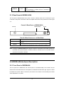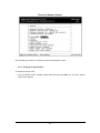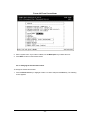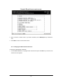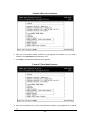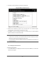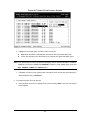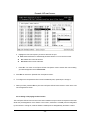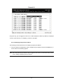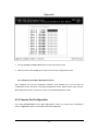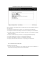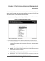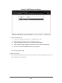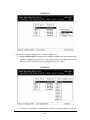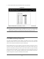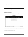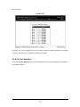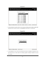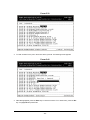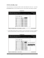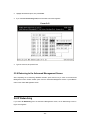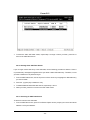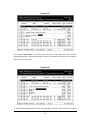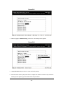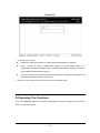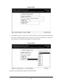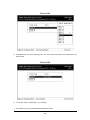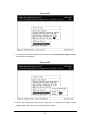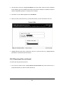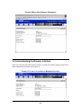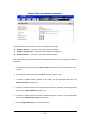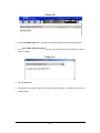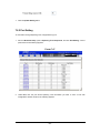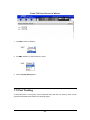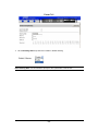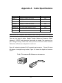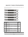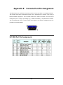
1
Intelligent Gigabit Ethernet Stackable / Routing Switch 24 10/100 Mbps Ports + 2 modules slot WGSW-2402A 4-port Gigabit Ethernet + 4-slot WGSW-404 User Manual Trademarks Copyright PLANET Technology Corp. 2002. Contents subject to revision without prior notice. PLANET is a registered trademark of PLANET Technology Corp. to their respective owners. All other trademarks belong Disclaimer PLANET Technology does not warrant that the hardware will work properly in all environments and applications, and makes no warranty and representation, either implied or expressed, with respect to the quality, performance, merchantability, or fitness for a particular purpose. PLANET has made every effort to ensure that this User’s Manual is accurate; PLANET disclaims liability for any inaccuracies or omissions that may have occurred. Information in this User’s Manual is subject to change without notice and does not represent a commitment on the part of PLANET. PLANET assumes no responsibility for any inaccuracies that may be contained in this User’s Manual. PLANET makes no commitment to update or keep current the information in this User’s Manual, and reserves the right to make improvements to this User’s Manual and/or to the products described in this User’s Manual, at any time without notice. If you find information in this manual that is incorrect, misleading, or incomplete, we would appreciate your comments and suggestions. FCC Warning This equipment has been tested and found to comply with the limits for a Class A digital device, pursuant to Part 15 of the FCC Rules. These limits are designed to provide reasonable protection against harmful interference when the equipment is operated in a commercial environment. This equipment generates, uses, and can radiate radio frequency energy and, if not installed and used in accordance with the Instruction manual, may cause harmful interference to radio communications. Operation of this equipment in a residential area is likely to cause harmful interference in which case the user will be required to correct the interference at his own expense. CE Mark Warning This is a Class A product. In a domestic environment, this product may cause radio interference, in which case the user may be required to take adequate measures. Revision PLANET Intelligent Stackable/Routing Switch User's Manual FOR MODEL: WGSW-2402A, WGSW-404 REVISION: 1.2 Part No.: EM-WG24A Table of Contents CHAPTER 1 INTRODUCTION ........................................................................................................... 1 1.1 PACKAGE CONTENTS .................................................................................................................. 1 1.2 FEATURES ................................................................................................................................. 2 1.3 SPECIFICATION ........................................................................................................................... 3 1.4 HOW TO USE THIS MANUAL ......................................................................................................... 4 CHAPTER 2 INSTALLATION............................................................................................................. 6 2.1 WGSW-2402A HARDWARE DESCRIPTION.................................................................................... 6 2.1.1 Front Panel of WGSW-2402A............................................................................................ 6 2.1.2 LEDs of WGSW-2402A ..................................................................................................... 7 2.1.3 Rear Panel of WGSW-2402A ............................................................................................ 8 2.2 WGSW-404 HARDWARE DESCRIPTION ........................................................................................ 8 2.2.1 Front Panel of WGSW-404................................................................................................ 8 2.2.2 LEDs of WGSW-404 ......................................................................................................... 9 2.2.3 Rear Panel of WGSW-404 .............................................................................................. 10 2.3 MODULE HARDWARE DESCRIPTION ............................................................................................ 10 2.3.1 Gigabit Expansion Module............................................................................................... 10 2.3.2 100Base-FX Expansion Module .......................................................................................11 2.4 INSTALLING THE SWITCH ........................................................................................................... 12 2.4.1 Pre-Installation Considerations........................................................................................ 13 2.4.2 Desktop or Shelf Mounting .............................................................................................. 13 2.4.3 Rack-Mounting................................................................................................................ 14 CHAPTER 3 CONFIGURATION ...................................................................................................... 15 3.1 MANAGEMENT ACCESS OVERVIEW ............................................................................................. 15 3.1.1 Administration Console ................................................................................................... 16 3.1.2 Direct Access .................................................................................................................. 16 3.1.3 Modem Port Access ........................................................................................................ 17 3.2 WEB MANAGEMENT .................................................................................................................. 17 3.3 SNMP-BASED NETWORK MANAGEMENT .................................................................................... 18 3.4 PROTOCOLS ............................................................................................................................ 18 3.4.1 Virtual Terminal Protocols................................................................................................ 18 3.4.2 SNMP Protocol ............................................................................................................... 18 3.4.3 Management Architecture ............................................................................................... 19 CHAPTER 4 MENU-DRIVEN CONSOLE MANAGEMENT............................................................... 20 4.1 LOGGING ON TO THE SWITCH ..................................................................................................... 20 4.2 NAVIGATING THROUGH THE CONSOLE INTERFACE ........................................................................ 21 4.3 PERFORMING BASIC MANAGEMENT ACTIVITIES ............................................................................ 21 4.3.1 General Management Configuration ................................................................................ 22 4.3.1.1 Changing the System Name........................................................................................................ 23 4.3.1.2 Changing the Contact and Location ............................................................................................ 24 4.3.1.3 Changing the Administration Password....................................................................................... 25 4.3.1.4 Changing the Guest Password .................................................................................................... 27 4.3.1.5 Statistic Collection ....................................................................................................................... 28 4.3.1.6 Reboot-On-Error.......................................................................................................................... 29 4.3.1.7 Telnet Logins ............................................................................................................................... 30 4.3.1.8 Remote Http Login....................................................................................................................... 31 4.3.1.9 Returning to the Basic Management Screen ............................................................................... 32 4.3.2 LAN Port Configuration ................................................................................................... 32 4.3.2.1 Changing the Speed and Flow Control........................................................................................ 33 4.3.2.2 Hiding or Displaying the Port Column.......................................................................................... 36 4.3.2.3 Displaying a Physical Port Address............................................................................................. 37 4.3.2.4 Returning to the Basic Management Screen............................................................................... 38 4.3.3 Console Port Configuration ............................................................................................. 38 4.3.3.1 Changing the Console Baud Rate ............................................................................................... 39 4.3.3.2 Selecting a Flow Control Method................................................................................................. 40 4.3.3.3 Enabling or Disabling Modem Control Options............................................................................ 41 4.3.3.4 Specifying a Modem Setup String ............................................................................................... 42 4.3.3.5 Enabling or Disabling SLIP.......................................................................................................... 43 4.3.3.6 Specifying a SLIP Address .......................................................................................................... 45 4.3.3.7 Specifying a SLIP Subnet Mask .................................................................................................. 46 4.3.3.8 Returning to the Basic Management Screen ............................................................................... 47 CHAPTER 5 PERFORMING ADVANCED MANAGEMENT ACTIVITIES ......................................... 48 5.1 SWITCHING DATABASE CONFIGURATION ...................................................................................... 49 5.2 VLAN & PVID PERSPECTIVE .................................................................................................... 50 5.2.1 Default VLAN .................................................................................................................. 51 5.2.2 Obtaining a VLAN Perspective ........................................................................................ 51 5.2.2.1 Creating a New VLAN ................................................................................................................. 52 5.2.2.2 Adding New Switch Ports ............................................................................................................ 55 5.2.2.3 Deleting a VLAN ID ..................................................................................................................... 60 5.2.2.4 Viewing VLAN Activities .............................................................................................................. 61 5.2.2.5 Viewing VLAN Settings................................................................................................................ 63 5.2.2.6 Adding Ports................................................................................................................................ 64 5.2.2.7 Deleting Ports.............................................................................................................................. 67 5.2.3 Configuring PVID ............................................................................................................ 67 5.3 IP MULTICAST GROUP PERSPECTIVE.......................................................................................... 69 5.4 MAC ADDRESS PERSPECTIVE ................................................................................................... 73 5.5 PORT PERSPECTIVE ................................................................................................................. 74 5.5.1 Per Port VLAN Activities.................................................................................................. 75 5.5.2 Scrolling Through MAC Addresses.................................................................................. 77 5.5.3 Hiding or Displaying the Port Column .............................................................................. 77 5.5.4 Per Port Statistics............................................................................................................ 78 5.5.5 Per Port Mac Limit........................................................................................................... 81 5.5.6 Returning to the Advanced Management Screen............................................................. 82 5.6 IP NETWORKING ...................................................................................................................... 82 5.6.1 IP and RIP Settings......................................................................................................... 83 5.6.2 ARP Table Setting........................................................................................................... 87 5.6.2.1 Adding Static ARP Table Entries ................................................................................................. 87 5.6.2.2 Deleting Static ARP Table Entries ............................................................................................... 90 5.6.2.3 Searching for ARP Table Entries................................................................................................. 90 5.6.3 Routing Table.................................................................................................................. 91 5.6.3.1 Adding Routing Table Entries ...................................................................................................... 93 5.6.3.2 Deleting Routing Table Entries.................................................................................................... 95 5.6.3.3 Searching for Routing Table Entries............................................................................................ 95 5.6.4 DHCP Gateway Settings ................................................................................................. 96 5.6.5 Ping Settings................................................................................................................. 100 5.7 BRIDGING .............................................................................................................................. 104 5.8 STATIC FILTERING ................................................................................................................... 107 5.8.1 Source MAC Address and Destination MAC Address Out-Filters ................................... 107 5.8.2 MAC Address In-Filters ................................................................................................. 109 5.9 SPANNING TREE FUNCTIONS ....................................................................................................110 5.9.1 Spanning Tree Protocol Configurations........................................................................... 111 5.9.2 Spanning Tree Port States .............................................................................................116 5.9.3 Spanning Tree Path Costs..............................................................................................118 5.9.4 Spanning Tree Port Priorities......................................................................................... 120 5.10 SNMP FUNCTIONS............................................................................................................... 121 5.11 STACKING ............................................................................................................................ 132 5.11.1 Stacking Basic Setting ................................................................................................. 132 5.11.2 Stack IP Setting........................................................................................................... 137 5.11.3 Stack Port Mapping ..................................................................................................... 140 5.12 OTHER PROTOCOLS ............................................................................................................. 140 5.13 PORT TRUNKING .................................................................................................................. 143 5.14 PORT MIRRORING................................................................................................................. 146 5.15 SETTING QUALITY OF SERVICE PARAMETERS .......................................................................... 150 5.15.1 Basic concept.............................................................................................................. 150 5.15.1.1 QoS model .............................................................................................................................. 150 5.15.1.2 Four QoS Profile...................................................................................................................... 152 5.15.1.3 Delay Bound............................................................................................................................ 153 5.15.1.4 Strict Priority and Best Effort.................................................................................................... 153 5.15.1.5 Weighted Fair Queuing............................................................................................................ 154 5.15.1.6 Shaper and DiffServ Expedited Forwarding ............................................................................ 154 5.15.1.7 Rate Control ............................................................................................................................ 154 5.15.1.8 WRED Drop Threshold Management Support ........................................................................ 155 5.15.1.9 QoS Flow Control .................................................................................................................... 155 5.15.1.10 Mapping to IETF Diffserv Classes ......................................................................................... 156 5.15.2 Configure QoS parameter ........................................................................................... 157 5.15.2.1 Setting Global Settings............................................................................................................ 158 5.15.2.2 Specifying TCP/UDP Logical Port Settings ............................................................................. 163 5.15.2.2.1 User-Defined Port ............................................................................................................ 164 5.15.2.2.2 Well-Known Port .............................................................................................................. 168 5.15.2.2.3 Range Port....................................................................................................................... 169 5.15.2.3 Specifying the QoS VLAN Priority ........................................................................................... 173 5.15.2.4 Specifying the ToS Priority....................................................................................................... 175 5.15.2.5 Selecting a QoS Profile ........................................................................................................... 177 5.15.2.5.1 Megabit Profile................................................................................................................. 178 5.15.2.5.2 Gigabit Profiles ................................................................................................................ 182 5.15.2.6 Specifying the Port Configuration............................................................................................ 184 5.15.2.7 Selecting Rate Control Parameters ......................................................................................... 186 5.16 SENDING AND RECEIVING FILES ............................................................................................. 190 5.16.1 Receiving Files via TFTP............................................................................................. 191 5.16.2 Sending Files via TFTP ............................................................................................... 193 5.16.3 Receiving Files via Kermit ........................................................................................... 195 5.16.4 Sending Files via Kermit.............................................................................................. 196 CHAPTER 6 WEB-BASED BROWSER MANAGEMENT............................................................... 199 6.1 LOGGING ON TO THE SWITCH ................................................................................................... 199 6.2 UNDERSTANDING THE BROWSER INTERFACE ............................................................................. 200 6.3 PERFORMING FILE ACTIVITIES ................................................................................................. 201 6.3.1 Receiving Files via TFTP............................................................................................... 202 6.4 PERFORMING BASIC SETUP ACTIVITIES .................................................................................... 203 6.4.1 General Management Configuration .............................................................................. 203 6.4.2 Configuring LAN Ports................................................................................................... 205 6.4.3 Console Port Configuration ........................................................................................... 209 CHAPTER 7 PERFORMING ADVANCED SETUP ACTIVITIES .................................................. 213 7.1 MAC ADDRESS MANAGEMENT ................................................................................................ 214 7.1.1 Per VLAN View ............................................................................................................. 215 7.1.2 Per Port View ................................................................................................................ 216 7.1.3 Individual MAC View ..................................................................................................... 218 7.2 IP NETWORKING .................................................................................................................... 219 7.2.1 IP and RIP Settings....................................................................................................... 220 7.2.2 Default Gateway Settings .............................................................................................. 224 7.2.3 ARP Table Settings ....................................................................................................... 225 7.2.4 DHCP Gateway Settings ............................................................................................... 225 7.3 PER PORT STATISTICS ............................................................................................................ 227 7.4 BRIDGING .............................................................................................................................. 228 7.5 STATIC MAC FILTERS ............................................................................................................. 229 7.5.1 Adding Source MAC Address Out-Filters....................................................................... 230 7.5.2 Deleting Source MAC Address Out-Filters..................................................................... 232 7.5.3 Adding Destination MAC Address Out-Filters ................................................................ 233 7.5.4 Deleting Destination MAC Address Out-Filters .............................................................. 234 7.6 IP MULTICAST GROUP ............................................................................................................ 235 7.7 VLAN & PVID PERSPECTIVE .................................................................................................. 237 7.7.1 VLAN Configuration ...................................................................................................... 238 7.7.1.1 Adding a VLAN.......................................................................................................................... 238 7.7.1.2 Updating VLAN Information....................................................................................................... 241 7.7.1.3 Deleting a VLAN........................................................................................................................ 242 7.7.2 PVID Setting ................................................................................................................. 243 7.8 SPANNING TREE PERSPECTIVE ................................................................................................ 244 7.8.1 Configurations............................................................................................................... 245 7.8.2 Port Setting ................................................................................................................... 247 7.9 VIEWING AND/OR CHANGING SNMP PARAMETERS..................................................................... 249 7.10 CONFIGURING GVRP AND IGMP ........................................................................................... 251 7.11 PORT TRUNKING................................................................................................................... 252 7.12 PORT MIRRORING................................................................................................................. 254 7.13 SELECTING STACKING SETTINGS ............................................................................................ 257 CHAPTER 8 SNMP AND RMON MANAGEMENT....................................................................... 259 8.1 OVERVIEW ............................................................................................................................. 259 8.2 SNMP AGENT AND MIB-2 (RFC1213) .................................................................................... 260 8.3 RMON MIB (RFC 1757) AND BRIDGE MIB (RFC 1493)........................................................... 260 8.3.1 RMON Groups Supported ............................................................................................. 261 8.3.2 Bridge Groups Supported.............................................................................................. 261 8.4 PLANET PRIVATE MIB........................................................................................................... 262 APPENDIX A CABLE SPECIFICATIONS.................................................................................... 263 APPENDIX B EXAMPLE OF STACKING SWITCHES................................................................. 265 APPENDIX C VLAN .................................................................................................................... 267 C.1 ASSIGNING PORTS TO VLANS ................................................................................................. 268 C.1.1 VLAN Classification ...................................................................................................... 268 C.1.2 Port Overlapping .......................................................................................................... 268 C.1.3 Port-based VLANs........................................................................................................ 268 C.1.4 Automatic VLAN Registration (GVRP) .......................................................................... 268 C.2 FORWARDING TAGGED/UNTAGGED FRAMES.............................................................................. 269 C.3 CONNECTING VLAN GROUPS ................................................................................................. 270 APPENDIX D VLAN OVERLAPPING.......................................................................................... 272 APPENDIX E CONSOLE PORT PIN ASSIGNMENT ................................................................... 275 B.1 DB9 PORT PIN ASSIGNMENTS................................................................................................. 275 B.2 CONNECTION FROM SWITCH'S SERIAL PORT TO PC'S 9-PIN COM PORT ..................................... 276 B.3 CONNECTION FROM SWITCH'S SERIAL PORT TO MODEM'S 25-PIN DCE PORT .............................. 276 B.4 CONNECTION FROM SWITCH'S SERIAL PORT TO PC'S 25-PIN DTE PORT..................................... 277 CHAPTER 1 INTRODUCTION WGSW-404 and WGSW-2402A are ultra-fast high-performance switches with non-blocking switch fabric of 16Gbps and 12.8Gbps. WGSW-404 is a backbone switch with 4-port 10/100/1000Mbps RJ-45 and 4-slot for media expansion. WGSW-2402A is designed to be a workgroup switch with 24-port 10/100Mbps RJ-45 and 2-slot for media expansion. Their expansion slots support 1000Base-T, 1000Base-SX and 100Base-FX modules that provide great flexibility on enterprise and FTTB application. In the following section, the short term “WGSW” will be used to represent both WGSW-2402A and WGSW-404 The WGSW switch can be stacked up to 8 units together through Ethernet interface and managed by single IP. You can stack 8 WGSW-2402A to get up to 192 100Base-TX ports plus 2 Gigabit port or 8 WGSW-404 to get 50 Gigabit ports in single stack. Mix them in a single stack is also possible to get maximum flexibility. Most stacked switches are limited by the length of a proprietary stack cable, WGSW switch, however, the maximum distance between two stacked switches can be up to 2 kilometers using Ethernet stack connectivity. Designed as the Layer 2 switch but with layer 3 software routing function, the WGSW can easily fit in your network configuration and can be executed for its management functions through the console telnet and the web. SNMP MIBII, Bridge MIB, RMON groups 1,2,3,9 and enterprise private MIB are also supported to get the maximum management functionality. The standard IEEE 802.1Q with VLAN tagging feature makes logically separating nodes easier, with up to 128 VLAN groups allowed on the WGSW switch. IGMP snooping is provided to prevent flooding of IP multicast traffic. Port security and MAC addresses filtering are also included as a standard feature to enhance overall network access security. 8 priority queues on Gigabit port and 4 on 10/100port are provided with versatile scheduling methods including delay bound, strict priority, WFQ and best effort. bandwidth and priority they need. This ensures critical applications get the Rate control is also supported to allow bandwidth allocation based on ports. Throughout this user’s manual, the Intelligent Gigabit Ethernet Switch, WGSW-404 and WGSW-2402A will be referred to as the Managed Switch or the Switch or WGSW. 1.1 Package Contents The package contains the following: -1- u One Intelligent Gigabit Ethernet Switch u One Power Cord u Rack Mounting Brackets u One Serial/Console Cable u User’s manual CD u Quick Installation Guide If any of these pieces are missing or damaged, please contact your dealer immediately, if possible, retain the carton including the original packing material, and use them against to repack the product in case there is a need to return it to us for repair. 1.2 Features u Complies with IEEE 802.3, 802.3u, 802.3z and 802.3ab Ethernet Standards, IEEE 802.3x flow control, 802.1D Spanning Tree, 802.1p QoS and 802.1Q VLAN. u Features Store-and-Forward mode with wire-speed filtering and forwarding rates u Support 16k MAC addresses u IEEE 802.3x full duplex PAUSE frame, half duplex back pressure flow control u Runt and CRC filtering eliminates erroneous packets to optimize network bandwidth u LED indicators for simple diagnostics and management u Auto-MDI/MDI-X on each 100Base-TX and 1000Base-T port u Software routing function with RIP, RIP-2, DHCP relay and proxy ARP support u Can be configured up to 128 groups of 802.1Q VLANs with GARP/GVRP supports u Support port trunking for maximum 4 ports per trunk u Support IP Multicast with IGMP snooping u Up to 8 units can be stacked by Ethernet connection and managed by single IP u Provide 4 priority queues on 10/100 ports and 8 priority queues on Gigabit ports u Queuing is based on IEEE 802.1p tag or ToS of IP layer u Configurable frame scheduling methods including delay bound, strict priority, weighted fair queuing and best effort u Rate control is supported on 10/100Mbps ports to provide 10 levels of rate (10Mbps to 100Mbps) u Support SNMP MIB II, Ethernet MIB, VLAN MIB, RMON group 1, 2, 3, 9 and enterprise private MIB u Support Port mirroring on WGSW-2402A -2- 1.3 Specification Product WGSW-2402A WGSW-404 Hardware Specification Ports 24 10/ 100Base-TX RJ-45 4 10/100/1000Base-T Auto-MDI/MDI-X ports Auto-MDI/MDI-X ports Module Slot 2 4 Supported Module 1000Base-SX/T Switch Fabric 1000Base-SX/T and 100Base-FX Through Ethernet interface. single IP 12.8Gbps Switch Processing Scheme Store-and-forward Throughput (packet per 6.547Mpps Stack Interface RJ-45 Up to 8 units can be managed by 16Gbps 11.904Mbps second) Address Table 16K entries Queue Buffer 2Mbytes Flow Control Weight Back pressure for half duplex, IEEE 802.3x Pause Frame for full duplex 430 x 350 x 44.5 mm, 1U high 4.4 kg 4.2 kg Power Requirement 100~240 VAC, 50-60 Hz Power Consumption 50 Watts maximum 60 Watts maximum Heat Dissipation 170 BTU/hr maximum 205 BTU/hr maximum Temperature Operating: 0~50ºC, Storage -40~70ºC Humidity Operating and Storage: 10% to 95%(Non-condensing) Dimensions 4Mbytes Network Management System Configuration Console port, Telnet, Web browser, SNMP/RMON Management Agent RMON MIB II, Ethernet MIB, RMON MIB, VLAN MIB and enterprise private MIB Groups 1, 2, 3, 9 (Statistics, History, Alarm and Event) Spanning Tree Algorithm IEEE 802.1D VLAN 802.1Q VLAN with GARP/GVRP, up to 128 VLANs supported Routing Static Address Filtering RIP, RIP-2, DHCP Relay, proxy ARP and ICMP Router Discovery Message Source and destination MAC addresses filtering IGMP Multicast Filtering Support IP multicast with IGMP snooping up to 64k groups Port trunking Up to 4 ports in a trunk. trunk groups support Port Mirroring 2 mirroring port supports QoS Based on IEEE 802.1p tag or ToS of IP layer Priority Queue 4 priority queues on 10/100 ports and 8 priority queues on Gigabit ports -3- 3 Up to 4 ports in a trunk. trunk groups support 4 QoS Scheduling Congestion Avoidance Rate Control Supports delay bound, strict priority, WFQ (Weighted Fair Queuing) and best effort service disciplines Supports WRED (Weighted Random Early Detection) drop threshold management 10 levels of rate (10 to 100%) configurable on 10/100Mbps port Standards Conformance Regulation Compliance FCC Part 15 Class A, CE Standards Compliance IEEE 802.3 (Ethernet) IEEE 802.3u (Fast Ethernet), IEEE 802.3z (1000Base-SX/LX), IEEE 802.3ab(1000Base-T), IEEE 802.1D (STP), IEEE 802.3x (full-duplex flow control), IEEE 802.1p (QoS), IEEE 802.1Q (VLANs) RFC 768 UDP RFC 783 TFTP RFC 791 IP RFC 792 ICMP RFC 826 ARP RFC 854 Telnet RFC 1058 RIP RFC 1122 Host Requirements RFC 1157 SNMP v1/v2 RFC 1256 ICMP Router Discover Protocol RFC 1213 MIB II RFC 1493 Bridge MIB RFC 1757 RMON 4 groups, statistics, history, alarms and events RFC 1812 IP Router Requirement RFC 2131 DHCP Relay RFC 2068 HTTP RFC 2236 IGMPv2 RFC 2674 VLAN MIB 1.4 How to Use this Manual This user’s manual is structured as follows: § Chapter 2, Installation explains the hardware functions of the Switch and how to physically install it. § Chapter 3, Configuration explains how to set up and modify the configuration of the Switch. § Chapter 4, Menu-Driven Console Management and Chapter 5 Performing Advanced Management Activities explains how to configure either locally through its RS-232 port or remotely via a Telnet session. § Chapter 6 Web-Based Configuration and Chapter 7 Performing Advanced Setup Activities allows you to access the Switch using the Web browser of your choice. § Chapter 8, SNMP and RMON Management allows you to access the Switch using SNMP -4- management feature. § Appendix provides cable specification and more information regarding to stack and VLAN. -5- CHAPTER 2 INSTALLATION This Chapter describes the hardware function of the Switches and shows how to install it on the desktop or shelf. Basic knowledge of networking is assumed. Read this chapter completely before continuing. 2.1 WGSW-2402A Hardware Description 2.1.1 Front Panel of WGSW-2402A The front panel of the Switch has 24 RJ-45 ports for 10/100 Mbps in the middle. The port status LEDs are indicated at the left. The expansion modules are situated at the right. Figure 2-1 shows a front panel of the Switch. Table 2-1 shows the port function of the Switch. The functionality of the LEDs will be explained in 2.1.4 LEDs. FIGURE 2-1 FRONT PANEL LEDs Status LEDs 10/100 RJ-45 Ports Expansion Modules TABLE 2-1 PORT FUNCTION Ports 10/100 Expansion Ports # of Ports 24 2 Description These RJ-45 ports support network speeds of either 10Mbps or 100 Mbps, and can operate in half- or full-duplex modes. These ports provide for the installation of one or two expansion modules that establish a Fast or Gigabit Ethernet connection. Note: You may install an 1000Base-SX, 1000Base-T or 100Base-FX expansion module and use fiber optic or category 5 cabling -6- 2.1.2 LEDs of WGSW-2402A The LEDs indicate the status of 10/100 Mbps Ethernet ports, Over Heat, Fan Failure and Power. Figure 2-2 shows the LED panel of the Switch. Table 2-2 shows the functions of power and status LEDs. Table 2-3 shows the functions of the port status LEDs. FIGURE 2-2 LEDS PANEL Status LED 10/100 Port Status LEDs Power LED The LEDs are explained in the following tables. TABLE 2-2 POWER AND STATUS LEDS LED Color PWR Green Over Heat Red Fan Failure Red Function Lights to indicate that the Switch has power. Lights to indicate that the Switch exceeds its operational temperature. Lights to indicate that the fans are not active. TABLE 2-3 PORT STATUS LEDS LED Color Link/Act Green 100/10 Green Function Lights to indicate that the Switch is successfully connecting to the network. Blinks to indicate the Switch is actively receiving or sending the data over the port. Lights to indicate that the port is operating at 100 Mbps. Off to indicate that the port is operating at 10 Mbps while the port’s Link is on. -7- FDX/COL Yellow Lights to indicate that the port is operating in full-duplex mode. Blinks periodically to indicate that the connection is experiencing collisions. 2.1.3 Rear Panel of WGSW-2402A The rear panel of WGSW-2402A has a power connector, a Buzzer button and a console port. Figure 2-3 shows a rear panel of the Switch. Table 2-5 explains the function of the ports shown in the Figure 2-4. FIGURE 2-3 REAR PANEL OF WGSW-2402A Console Buzzer Button Power TABLE 2-4 PORT FUNCTION OF THE REAR PANEL Port Power Console Function This is where you will connect the AC power cord. 100~240VAC is allowed. This is where you will connect to the RS-232 serial port on your PC for configuring the management function, discussed in Chapter 3. Note: To depress the Buzzer button will change the reaction of the buzzer. If the button is set to on, the buzzer will ring as the system is under the status of overheat. Set to off, the buzzer will not work even if the system overheats. 2.2 WGSW-404 Hardware Description 2.2.1 Front Panel of WGSW-404 The front panel of the WGSW-404 has 4 RJ-45 ports for 10/100/1000 Mbps in the middle. The port status LEDs are indicated at the left. The expansion modules are situated at the right. Figure 2-3 shows the Switch’s front panel. Table 2-4 shows the port function of the Switch. The functionality of the LEDs will be explained in 2.2.2 LEDs. -8- FIGURE 2-4 FRONT PANEL OF WGSW-404 Console Status LEDs 10/100/1000 Mbps ports Expansion Ports Table 2-5 Port Function TABLE 2-5 PORT FUNCTION Ports # of Ports Console 1 10/100/1000 4 Expansion Ports Description This is where you can connect to the RS-232 serial port on your PC for configuring the management function. These RJ-45 ports support network speeds of 10, 100 or 1000 Mbps, and can operate in full-duplex modes. These ports provide for the installation of one or two expansion modules that establish a Fast or Gigabit Ethernet connection. Note: You may install an 1000Base-SX or 1000Base-T expansion module and use fiber optic or category 5 cabling. 4 2.2.2 LEDs of WGSW-404 The LEDs indicate the status of 10/100/1000 Mbps Ethernet ports, Over Heat, Fan Failure and Power. The LEDs are explained in the following tables. TABLE 2-6 POWER AND STATUS LEDS LED Color Power Green Over Heat Red Fan Failure Red Function Lights to indicate that the Switch has power. Lights to indicate that the Switch exceeds its operational temperature. Lights to indicate that the fans are not active. TABLE 2-7 PORT STATUS LEDS LED Color Act Green FDX/COL Yellow 1000 Green 100 Green 10 Yellow Function Lights to indicate the Switch is actively receiving or sending the data over the port. Lights green to indicate that the port is operating in full-duplex mode. Blinks orange periodically to indicate that the connection is experiencing collisions. Lights to indicate that the Switch is sending or receiving data at 1000 Mbps. Lights to indicate that the Switch is sending or receiving data at 100 Mbps. Lights to indicate that the Switch is sending or receiving data at 10 Mbps. -9- 2.2.3 Rear Panel of WGSW-404 The rear panel of WGSW-404 has a power connector, a Buzzer button and a console port. Figure 2-3 shows a rear panel of the Switch. Table 2-5 explains the function of the ports shown in the Figure 2-4. FIGURE 2-5 REAR PANEL OF WGSW-404 Buzzer Button Power TABLE 2-8 PORT FUNCTION OF THE REAR PANEL Port Power Function This is where you will connect the AC power cord. Note: To depress the Buzzer button will change the reaction of the buzzer. If the button is set to on, the buzzer will ring as the system is under the status of overheat. Set to off, the buzzer will not work even if the system overheats. 2.3 Module Hardware Description 2.3.1 Gigabit Expansion Module Figure 2-6 show that front panel of gigabit expansion module. modules status LEDs. - 10 - Table 2-9 and Table 2-10 show that FIGURE 2-6 GIGABIT EXPANSION MODULE WGSW-C1GT Module Status LEDs WGSW-C1SX Module Status LEDs TABLE 2-9 WGSW-C1GT/SX STATUS LEDS WGSW-C1GT LED Color 1000 Green 100 Green 10 Yellow FDX/COL Yellow Act Green Function Lights to indicate that the Switch is sending or receiving data at 1000 Mbps. Lights to indicate that the Switch is sending or receiving data at 100 Mbps. Lights to indicate that the Switch is sending or receiving data at 10 Mbps. Lights green to indicate that the port is operating in full-duplex mode. Blinks orange periodically to indicate that the connection is experiencing collisions. Lights to indicate that the connection is acting. TABLE 2-10 WGSW-C1SX STATUS LEDS WGSW-C1SX LED Color 1000 Green Act Green FDX/COL Yellow Function Lights to indicate that receiver of fibre port is in normal optical input levels. Lights to indicate that the connection is acting. Lights to indicate that the port is operating at full duplex. This port does not support half duplex. 2.3.2 100Base-FX Expansion Module Figure 2-5 show that front panel of 100Base-FX expansion module. status LEDs. - 11 - Table 2-7 show that modules FIGURE 2-7 100BASE-FX EXPANSION MODULE WGSW-C1ST Module Status LEDs WGSW-C1SC Module Status LEDs TABLE 2-11 100BASE-FX MODULE STATUS LEDS WGSW-C1SC / WGSW-C1ST LED Color 100 Green Act Green FDX/COL Yellow Function Lights to indicate that receiver of fibre port is in normal optical input levels. Lights to indicate that the connection is acting. Lights to indicate that the port is operating at full duplex. Blinks orange periodically to indicate that the connection is experiencing collisions. 2.4 Installing the Switch The Switch is designed for office use, where it can be free standing, desktop-mounted, or mounted in most standard 19-inch equipment racks. If you prefer, you can rack-mount the Switch in a wiring closet or equipment room using two mounting brackets and six screws. When choosing a location for the Switch, observe the following guidelines: l Make sure the Switch is accessible and that the cables can be connected easily. l Keep cabling away from sources of electrical noise such as radios, transmitters, and broadband amplifiers as well as power lines and fluorescent lighting fixtures. l Prevent water or moisture from entering the Switch case. l Make sure there are no obstructions to restrict airflow around the Switch. We recommend that you provide a minimum of 25 millimeter (1-inch) clearance. l Do not place liquids or other objects on top of the Switch. l If the Switches are freestanding, do not stack more than four switches on top of one another. - 12 - 2.4.1 Pre-Installation Considerations Fast Ethernet Topology Considerations If you will be using the Switch for Fast Ethernet (100 Mbps) operation, observe the following guidelines: l The maximum unshielded twisted-pair (UTP) cable length is 100 meters (328 feet) over Category 5 cable. l Single-repeater topologies permit a total network span of 325 meters (1066 feet). Full-Duplex Considerations The Switch provides full-duplex support for its Fast Ethernet ports. Full-duplex operation allows frames to be sent and received simultaneously, doubling a link’s potential data throughput. If you will be using the Switch in full-duplex mode, the maximum UTP cable length is 100 meters (328 feet) over Category 5 cable. 2.4.2 Desktop or Shelf Mounting To install the Switch on a desktop or shelf, simply complete the following steps: Step 1 Place the Switch on a desktop or shelf near an AC power source. Step 2 Keep enough ventilation space between the Switch and the surrounding objects. Note: When choosing a location, keep in mind the environmental restrictions. Please also refer to Chapter 1, section 1.3 product specification for the details. Step 3 Connect the Switch to network devices. A. Connect one end of a standard network cable to the 10/100 RJ-45 ports on the front of the Switch. B. Connect the other end of the cable to the network devices such as printer servers, workstations or routers. C. Note: It is strongly recommended to use the UTP Category 5 network cabling with RJ-45 tips for the network connection. For more information, please see the Cable Specifications in Appendix A, Cable Specifications. Step 4 Supply power to the Switch. A. Connect one end of the power cable to the Switch. B. Connect the power cube end of the power cable to a standard wall outlet. When the Switch receives power, the Power LED should remain solid Green. - 13 - 2.4.3 Rack-Mounting The following procedure describes how to install the Switch in a standard 19-inch rack. l Disconnect all cables from the Switch. l Remove all adhesive pads from the bottom of the Switch. Step 1 Place the Switch right side up on a hard flat surface, with the front panel facing you. Step 2 Locate a mounting bracket over the mounting holes on one side of the Switch FIGURE 2-8 LOCATING A MOUNTING BRACKET Step 3 Insert three screws and use a screwdriver to secure. Step 4 Repeat the two previous steps for the other side of the Switch. Step 5 Insert the Switch into the 19-inch rack and secure with suitable screws. Make sure the ventilation holes on the Switch are not obstructed. Step 6 Connect the cables to the back of the Switch. - 14 - CHAPTER 3 CONFIGURATION This chapter explains the methods that you can use to configure management access to the Switch. It describes the types of management applications and the communication and management protocols that deliver data between your management device (workstation or personal computer) and the system. It also contains information about port connection options. This chapter covers the following topics: l Management Access Overview l Key Concepts l Key Guidelines for Implementation l Administration Console Access l Web Management Access l SNMP Access l Standards, Protocols, and Related Reading 3.1 Management Access Overview The Switch gives you the flexibility to access and manage the Switch using any or all of the following methods: l An administration console l Web browser interface l An external SNMP-based network management application The administration console and Web browser interface support are embedded in the Switch software and are available for immediate use. Each of these management methods has their own advantages. Table 3-1 compares the three management methods. TABLE 3-1 COMPARISONS OF THREE MANAGEMENT METHODS Management Advantages Method l l Administration l console l l Web browser l Disadvantages No IP address or subnet needed l Text-based Telnet functionality and HyperTerminal l built into Windows 95/98/NT/2000/XP l operating systems Secure Ideal for configuring the Switch l remotely Compatible with all popular browsers - 15 - Must be near switch or use dial-up connection Not convenient for remote users Modem connection may prove to be unreliable or slow Security can be compromised (hackers need only know the IP address and subnet mask) l l l l Can be accessed from any location l Most visually appealing Communicates with switch functions at l the MIB level Based on open standards l SNMP Agent l l May encounter delay times on poor connections Requires SNMP manager software Least visually appealing of all three methods Some settings require calculations Security can be compromised (hackers need only know the community name) 3.1.1 Administration Console The administration console is an internal, character-oriented, menu-driven user interface for performing system administration such as displaying statistics or changing option settings. Using this method, you can view the administration console from a terminal, personal computer, Apple Macintosh, or workstation connected to the Switch’s console (serial) port. There are two ways to use this management method: via direct access or modem port access. The following sections describe these methods. For more information about using the console, refer to Chapter 4 Menu-Driven Console Management. 3.1.2 Direct Access Direct access to the administration console is achieved by directly connecting a terminal or a PC equipped with a terminal-emulation program (such as HyperTerminal) to the Switch console (serial) port. When using this management method, a null-modem cable is required to connect the Switch to the PC. After making this connection, configure the terminal-emulation program to use the following parameters: The default parameters are: l 115,200 bps l 8 data bits l No parity l 1 stop bit You can change these settings, if desired, after you log on. This management method is often preferred because you can remain connected and monitor the system during system reboots. Also, certain error messages are sent to the serial port, regardless of the interface through which the associated action was initiated. A Macintosh or PC attachment can use any terminal-emulation program for connecting to the terminal serial port. A workstation attachment under UNIX can use an emulator such as TIP. - 16 - 3.1.3 Modem Port Access You can access the Switch’s administration console from a PC or Macintosh using an external modem attached to the console (serial) port. The Switch management program provides a Console Port screen, accessible from the Basic Management screen, that lets you configure parameters for modem access (see Chapter 4 Menu-Driven Console Management). After configuring when you have configured the external modem from the administration console, the Switch transmits characters that you have entered as output on the modem port. The Switch echoes characters that it receives as input on the modem port to the current ad-ministration console session. The console appears to be directly connected to the external modem. 3.2 Web Management The Switch provides a browser interface that lets you configure and manage the Switch remotely. After you set up your IP address for the Switch, you can access the Switch’s Web interface applications directly in your Web browser by entering the IP address of the Switch. You can then use your Web browser to list and manage switch configuration parameters from one central location, just as if you were directly connected to the Switch’s console port. For more information, see Chapter 5, Browser Management. Web Management requires either Microsoft Internet Explorer 4.01 or later or Netscape Navigator 4.03 or later. l Netscape Navigator — if you use Netscape Navigator 4.03 or 4.04, install the Netscape JDK 1.1 Patch. Download the patch from the following location: http://www.netscape.com/ If you encounter problems accessing Help files when you use Netscape, clear the browser memory cache and disk cache, and restart the browser. l Internet Explorer — if you use Internet Explorer 4.01, install the latest 4.01 Service Pack 1. This service pack makes Internet Explorer Year 2000 compliant and fixes other product-support issues. Download the 4.01 Service Pack 1 from the following location: http://www.microsoft.com/msdownload/iebuild/ie4sp1_win32/en/ie4sp1_win32.htm If the above link is unavailable, download the service pack from the Microsoft home page: http://www.microsoft.com - 17 - 3.3 SNMP-Based Network Management You can use an external SNMP-based application to configure and manage the Switch. This management method requires the SNMP agent on the Switch and the SNMP Network Management Station to use the same community string. This management method, in fact, uses two community strings: the get community string and the set community string. If the SNMP network management station only knows the set community string, it can read and write to the MIBs. However, if it only knows the get community string, it can only read MIBs. The default gets and sets community strings for the Switch are public. 3.4 Protocols The Switch supports the following protocols: l Virtual terminal protocols, such as Telnet l Simple Network Management Protocol (SNMP) 3.4.1 Virtual Terminal Protocols A virtual terminal protocol is a software program, such as Telnet, that allows you to establish a management session from a Macintosh, a PC, or a UNIX workstation. Because Telnet runs over TCP/IP, you must have at least one IP address configured on the Switch before you can establish access to it with a virtual terminal protocol. Note: Terminal emulation differs from a virtual terminal protocol in that you must connect a terminal directly to the console (serial) port. 3.4.2 SNMP Protocol Simple Network Management Protocol (SNMP) is the standard management protocol for multi-vendor IP networks. SNMP supports transaction-based queries that allow the protocol to format messages and to transmit information between reporting devices and data-collection programs. SNMP runs on top of the User Datagram Protocol (UDP), offering a connectionless-mode service. - 18 - 3.4.3 Management Architecture All of the management application modules use the same Messaging Application Programming Interface (MAPI). By unifying management methods with a single MAPI, configuration parameters set using one method (console port, for example) are immediately displayable by the other management methods (for example, SNMP agent of Web browser). The management architecture of the Switch adheres to the IEEE open standard. This compliance assures customers that the Switch is compatible with, and will interoperate with other solutions that adhere to the same open standard. - 19 - Chapter 4 Menu-Driven Console Management The Switch provides a menu-driven console interface for configuration purposes. The Switch can be configured either locally through its RS-232 port or remotely via a Telnet session. This chapter describes how to configure the Switch using its menu-driven console. The figures in this chapter will base on WGSW-2402A, for WGSW-404, however, the setup steps are the same. 4.1 Logging on to the Switch Enter the console interface factory default console name “admin” without password (or enter a user-defined pass-word if you changed the factory default password). The Switch Management screen in Figure 4-1 appears, with the Basic option highlighted. Note: Only one console and three telnet-users can log on to the Switch concurrently. However, it is not recommended that multiple users modify the configuration at the same time. FIGURE 4-1 SWITCH MANAGEMENT SCREEN l To perform basic management activities, see Section 4.3 “Performing Basic Management Activities”. l To perform advanced management activities, see Section 5 “Performing Advanced Management Activities”. - 20 - l To log out, highlight Logout and press Enter. l To save the current settings and remain in the configuration program, highlight Save Settings, press Enter. l To restore the factory default settings, highlight Restore Default Settings and press Enter. l To reboot, highlight Reboot and press Enter. 4.2 Navigating Through the Console Interface The console interface consists of a series of menu boxes. Each menu box has several options, which are listed vertically. A highlight in each box lets you select the option you wish to choose; pressing the Enter key activates the highlighted option. Table 4-1 shows the keys used for navigating through the console interface. TABLE 4-1 NAVIGATING THROUGH THE CONSOLE INTERFACE To... Press This Key... Move the highlight one line up in a menu box. Up arrow or K Move the highlight one line down in a menu box. Down arrow or J Move the highlight between screens. Tab Select the highlighted option. Enter Move to the previous menu. Escape 4.3 Performing Basic Management Activities Basic management activities consist of General, LAN port, and console port tasks. To perform basic management activities: 1. From the Switch Management screen (see Figure 4-1), highlight Basic Management and press Enter. The Basic Management screen in Figure 4-2 appears. - 21 - FIGURE 4-2 BASIC MANAGEMENT SCREEN 2. From the Basic Management screen, highlight the desired option and press the Enter key: l General lets you change the system name, location, administration and guest passwords, statistics collection, reboot-on-error, and remote Telnet login capability. See Section 4.3.1 “General Management Configuration”. l LAN Port lets you configure speed and flow control, link type, and physical address. See Section 4.3.2 “LAN Port Configuration”. l Console Port lets you change the console baud rate, flow control method, modem control, and modem setup string; enable or disable SLIP; and configure the SLIP address and SLIP subnet mask. See Section 4.3.3 “Console Port Configuration”. 4.3.1 General Management Configuration If you select General from the Basic Management screen (see Figure 4-2), the General screen in Figure 4-3 appears, with the System Name value highlighted. - 22 - FIGURE 4-3 GENERAL SCREEN Use the following procedure to configure the general management options. 4.3.1.1 Changing the System Name To change the system name: 1. From the General screen, highlight System Name and press the Enter key. The Enter System Name screen appears. - 23 - FIGURE 4-4 ENTER SYSTEM NAME 2. Enter a system name. If you make a mistake, use the Backspace key to delete the error. 3. Press Enter to return to the General screen. 4.3.1.2 Changing the Contact and Location To change the Contact and location: 1. Press the Down Arrow key to highlight Contact or Location and press the Enter key. The following screen appears. - 24 - FIGURE 4-5 ENTER CONTACT AND LOCATION 2. Enter a contact or location name. If you make a mistake, use the Backspace key to delete the error. 3. Press Enter to return to the General screen. 4.3.1.3 Changing the Administration Password To change the administration password: 1. Use the Down Arrow key to highlight admin Password and press the Enter key. The Enter Old Password screen appears. - 25 - FIGURE 4-6 ENTER OLD PASSWORD 2. Enter the current password. Each character you type appears as an asterisk (*). If you make a mistake, use the Backspace key to delete the error. 3. Press Enter. The Enter New Password screen appears. FIGURE 4-7 ENTER NEW PASSWORD 4. Enter the new password. For security, each password character you type appears as an asterisk (*). - 26 - 5. Press Enter. A screen prompts you to reenter the new password. FIGURE 4-8 REENTER NEW PASSWORD 6. Reenter the new password you typed in step 4 and press Enter. The “Password changed” message appears, confirming that the new password is in effect. 7. Press Enter to remove the message and return to the General screen. The admin password appears as asterisks in the admin Password field. Note: If the confirmation message does not appear, you may have typed the new password differently in steps 4 and 6. In this case, your new password did not take effect. Repeat this procedure, making sure to type the same new password in steps 4 and 6. It is recommended to change the password and keep the new password in a safe place for a secured management. 4.3.1.4 Changing the Guest Password To change the guest password: 1. Use the Down Arrow key to highlight guest Password and press the Enter key. The Enter New Password screen appears. - 27 - FIGURE 4-9 ENTER NEW PASSWORD 2. Enter a new guest password. If you make a mistake, use the Backspace key to delete the error. 3. Press Enter to return to the General screen. 4.3.1.5 Statistic Collection The statistic collection function allows the Switch to collect RMON and interface statistic data of each port. To enable or disable Statistic Collection to the Switch: 1. From the General screen, highlight Statistic Collection and press the Enter key. The following screen appears. - 28 - FIGURE 4-10 STATISTICS COLLECTION OPTIONS 2. Highlight one of the following choices: l Disabled — prevents statistic collection to the Switch. l Enabled — allows statistic collection to the Switch. 3. Press Enter to return to the General screen. 4.3.1.6 Reboot-On-Error To enable or disable Reboot-On-Error to the Switch: 1. From the General screen, highlight Reboot-On-Error and press the Enter key. The following screen appears. - 29 - FIGURE 4-11 2. Highlight one of the following choices: l Disabled — prevents the Switch to automatically reset when a fatal error is detected. This setting is useful when a persistent problem needs to be reported. l Enabled — allows the Switch to automatically reset when a fatal error is detected. 3. Press Enter to return to the General screen. 4.3.1.7 Telnet Logins To enable or disable Telnet logins to the Switch: 1. From the General screen, highlight Remote Telnet Login and press the Enter key. The following screen appears. - 30 - FIGURE 4-12 REMOTE TELNET LOGIN OPTIONS 2. Highlight one of the following choices: l Disabled prevents remote Telnet logins to the Switch. l Enabled allows remote Telnet logins to the Switch. This is the default setting. 3. Press Enter to return to the General screen. 4.3.1.8 Remote Http Login To enable or disable the function of Remote Http Login: 1. From the General screen, highlight Remote Http Login and press the Enter key. The following screen will appear: - 31 - FIGURE 4-13 REMOTE HTTP LOGIN OPTIONS 2. Highlight one of the following choices: Disable prevents remote HTTP login to the Switch. Enable allows remote HTTP login to the Switch. 3. Press Enter to go back to the General screen. 4.3.1.9 Returning to the Basic Management Screen After completing the general management activities, press the Esc key to exit the General screen and return to the Basic Management screen in Figure 4-2. Select another option from the Basic Management screen or press Esc to return to the Switch Management screen. 4.3.2 LAN Port Configuration If you select LAN Port from the Basic Management screen (see Figure 4-2), the LAN Port Configurations screen in Figure 4-14 appears, with Speed & Flow Control highlighted. - 32 - FIGURE 4-14 LAN PORT CONFIGURATIONS SCREEN Use the procedures in the following sections to configure the LAN port configuration options for one or more ports: l Speed & Flow Control - see Section 4.3.2.1 “Changing the Speed and Flow Control”. l Physical Address - see Section 4.3.2.2 “Displaying a Physical Port Address”. 4.3.2.1 Changing the Speed and Flow Control To change the line speed and flow control for one or more ports: 1. From the LAN Port Configurations screen, highlight Speed & Flow Control and press the Enter key. A screen similar to the following shows the current line speed settings for all ports. Note: If there are more ports below the bottom one shown in a screen, a v appears next to the bottom port in the screen (Port 12 in the following screen, for example). To view these ports, scroll the highlight to the bottom port shown and press the Down Arrow key. - 33 - FIGURE 4-15 2. To configure an individual port, highlight the port and press the Enter key. The Speed & Flow Cntl Options screen appears with the parameters for the port you selected. FIGURE 4-16 PORT SETTING OPTIONS 3. To change the line speed setting: a. Press Enter with the Line Speed value highlighted. The following Speed Options menu appears. - 34 - FIGURE 4-17 SPEED & FLOW CONTROL OPTIONS • b. Highlight the line speed option you want to select for the port. l Auto allows the Switch to automatically ascertain the line speed and duplex mode. l All the other selections force the Switch to use a specific line speed and duplex mode. Note: In the Speed Options screen, HD denotes half-duplex and FD denotes full-duplex. In addition, 1000M fiber ports have only Auto and 1000M/FD as selections, while 1000M copper ports have Auto, 1000M/FD, 100M/FD and 10M/FD options. c. Press Esc. You return to the Speed & Flow Cntl Options screen and the line speed setting you selected appears next to Line Speed. 4. To configure the flow control for this port: a. Press the Down Arrow key to highlight Flow Control and press Enter. The Flow Cntl Options screen appears. - 35 - FIGURE 4-18 FLOW CONTROL b. Highlight the flow control option you want to select for the port. l c. Auto allows the Switch to automatically ascertain whether or not to use flow control. l On enables flow control at all times. l Off disables flow control at all times. Press Esc. You return to the Speed & Flow Cntl Options screen and the flow control setting you selected appears next to Flow Control. 5. Press Esc to remove the Speed & Flow Cntl Options screen. 6. To configure the line speed and flow control for additional ports, repeat steps 1 through 5. 7. When you finish, press the Esc key from the Line Speed & Flow Control screen to return to the LAN Port Configurations screen. 4.3.2.2 Hiding or Displaying the Port Column The Line Speed & Flow Control screen has a column between the port number and speed columns that shows the port designations on the Switch. In this column, the Switch’s 10/100M ports are designated by the numbers 1 through 24, while the Switch’s 1000M ports are designated by the letters A and B. - 36 - FIGURE 4-19 Using the L key, you can toggle this column so it is either displayed or hidden. By default, it is displayed. To hide it, press the L key. To redisplay it, press the L key again. 4.3.2.3 Displaying a Physical Port Address The following procedure describes how to display a physical port address. 1. From the LAN Port Configurations screen, highlight Physical Address and press the Enter key. A screen similar to the following appears. Note: This screen also lets you use the L key to toggle the Port column, as described under Section 4.3.2.2 “Hiding or Displaying the Port Column”. - 37 - Figure 4-20 2. Use the Up Arrow and Down Arrow keys to scroll up and down the list. 3. When you finish, press the Esc key to return to the LAN Port Configurations screen. 4.3.2.4 Returning to the Basic Management Screen After completing the LAN port configuration activities, press the Esc key to exit the LAN Port Configurations screen and return to the Basic Management screen. Select another option from the Basic Management screen or press Esc to return to the Switch Management screen. 4.3.3 Console Port Configuration If you select Console Port from the Basic Management screen, the Console Port Configurations screen in Figure 4-21 appears, with the Baud Rate value highlighted. - 38 - FIGURE 4-21 CONSOLE PORT CONFIGURATIONS SCREEN Use the procedures in the following sections to configure the Console Port Configuration options for one or more ports: l To change the console baud rate, see section 4.3.3.1 “Changing the Console Baud Rate”. l To change the console flow control setting, see section 4.3.3.2 “Selecting a Flow Control Method”. l To enable or disable a console modem connection, see section 4.3.3.3 “Enabling or Disabling Modem Control Options”. l To specify a modem setup string, see section 4.3.3.4 “Specifying a Modem Setup String”. l To enable or disable SLIP, see section 4.3.3.5 “Enabling or Disabling SLIP”. l To specify a SLIP address, see section 4.3.3.6 “Specifying a SLIP Address”. l To specify a SLIP subnet mask, see section 4.3.3.7 “Specifying a SLIP Subnet Mask”. 4.3.3.1 Changing the Console Baud Rate To change the console baud rate: 1. From the Console Port Configurations screen, highlight Baud Rate and press the Enter key. A screen similar to the following shows the current console baud rate. - 39 - FIGURE 4-22 2. Highlight the baud rate you want to select for the console: l Auto allows the Switch to auto-baud between 9600 bps and 115,200 bps. If you choose this selection, choose the rest of your configuration selections. Then, when you exit the configuration program, press the Enter key one or more times until the Switch Login Password appears on your computer screen. l All the other selections force a specific console baud rate. 3. Press Enter. You return to the Console Port Configurations screen and the console port baud rate you selected appears in the Baud Rate field. 4.3.3.2 Selecting a Flow Control Method To change the console flow control used: 1. From the Console Port Configurations screen, highlight Flow Control and press the Enter key. A screen similar to the following shows the current console flow control method. - 40 - FIGURE 4-23 2. Highlight the flow control method you want to select for the console and press Enter. You return to the Console Port Configurations screen and the console port flow control method you selected appears in the Flow Control field. 4.3.3.3 Enabling or Disabling Modem Control Options To enable or disable modem control options for the console port: 1. From the Console Port Configurations screen, highlight Modem Control and press the Enter key. A screen similar to the following shows whether a console modem connection is enabled or disabled. - 41 - FIGURE 4-24 2. Highlight whether you want to enable or disable a modem connection to the console port. 3. Press Enter. You return to the Console Port Configurations screen and the modem control option you selected appears in the Modem Control field. Note: If you enable a modem connection, proceed to section 4.3.3.4 “Specifying a Modem Setup String” to specify the appropriate modem setup string. 4.3.3.4 Specifying a Modem Setup String If you enabled a modem connection to the console port, use the following procedure to specify a modem setup string: 1. From the Console Port Configurations screen, highlight Modem Setup String and press the Enter key. A screen similar to the following shows the current modem setup string option. - 42 - FIGURE 4-25 2. Highlight whether you want to use the default setup string or a custom setup string. 3. Press the Enter key. l If you highlight Default Setup String, you return to the Console Port Configurations screen and the default modem string appears in the Modem Setup String field. l If you highlight Custom Setup String, enter the custom string in the Enter Modem Setup String screen and press Enter again. You return to the Console Port Configurations screen and the custom setup string appears in the Modem Setup String field. Note: The default modem setup string configures the modem to auto answer. It works for all Hayes compatible modems. 4.3.3.5 Enabling or Disabling SLIP To enable or disable SLIP: 1. From the Console Port Configurations screen, highlight SLIP and press the Enter key. A screen similar to the following shows the current SLIP setting. - 43 - FIGURE 4-26 Highlight whether you want SLIP enabled or disabled and press Enter. You return to the Console Port Configurations screen and the SLIP option you selected appears in the SLIP field. Note: If you enable SLIP, a message tells you that the console port becomes accessible only through the SLIP protocol after you logout from the current console screen. To access the Switch, configure your PC to use SLIP, then use Telnet to interface with the Switch. If you use HyperTerminal, enabling SLIP and saving your selections displays the following screen, giving the impression that the Switch has “hung” when it is actually still operating. This occurs because HyperTerminal does not support SLIP. However, you can still access the Switch using Telnet, as described in the paragraph above. - 44 - FIGURE 4-27 If you enable SLIP, specify a SLIP address and subnet mask (see “Specifying a SLIP Address” and “Specifying a SLIP Sub-net Mask”). 4.3.3.6 Specifying a SLIP Address If you enabled SLIP, use the following procedure to enter an address that has a network part different than the network address of the Switch. (For more information, contact your network administrator.) 1. From the Console Port Configurations screen, highlight SLIP Address and press Enter. The following screen appears. - 45 - FIGURE 4-28 2. Enter the SLIP address. The address consists of numbers separated by periods. For example: 129.32.0.11 3. After you enter the SLIP address, press the Enter key. You return to the Console Port Configurations screen and your entry appears in the SLIP Address field. 4.3.3.7 Specifying a SLIP Subnet Mask If you are using SLIP, enter a suitable SLIP subnet mask. 1. From the Console Port Configurations screen, highlight SLIP Subnet Mask and press Enter. The Enter IP Subnet Mask screen appears. You must enter a SLIP address before you can enter a SLIP subnet mask. - 46 - FIGURE 4-28 2. Enter the SLIP subnet mask. The subnet mask consists of numbers separated by periods. For example: 255.255.255.0 3. After you enter the SLIP subnet mask, press the Enter key. You return to the Console Port Configurations screen and your entry appears in the SLIP Subnet Mask field. 4.3.3.8 Returning to the Basic Management Screen After completing the general management activities, press the Esc key to exit the Console Port Configurations screen and return to the Basic Management screen in Figure 4-2. Select another option from the Basic Management screen or press Esc to return to the Switch Management screen. - 47 - Chapter 5 Performing Advanced Management Activities Advanced management activities consist of the L2 switching database, IP Networking, bridging, static filtering, spanning tree, SNMP, other protocols (GVRP and IGMP), Port Trunking, port mirroring, QoS Setup and File Transfer. To perform advanced management activities: 1. From the Switch Management screen (see Figure 4-1), highlight Advanced Management and press Enter. The Advanced Management screen in Figure 5-1 appears. FIGURE 5-1 ADVANCED MANAGEMENT SCREEN 2. From the Advanced Management screen, highlight the desired option and press the Enter key: l L2 Switching DataBase — lets you view and change VLAN, PVID, MAC address, IP multicast group, MAC address, and port perspectives. See section 5.1 “Switching Database Configuration”. l IP Networking — lets you view or change IP settings, ARP and routing table parameters, DHCP gateway settings, and ping settings. See section 5.6 “IP Networking”. l Bridging — lets you view and change the aging period for a MAC address and the flood limit for all ports. See section 5.7 “Bridging”. l Static Filtering — lets you view, add, delete, or search all source or destination MAC addresses to be filtered. See section 5.8 “Static Filtering”. l Spanning Tree — lets you view and change spanning tree configurations, port states, path costs, and port priorities. See section 5.9 “Spanning Tree Functions”. - 48 - l SNMP — lets you view and change the SNMP configuration. See section 5.10 “SNMP Functions”. l Other Protocols — lets you view and change GVRP and IGMP settings. Refer to section 5.11 “Other Protocols”. l Port Trunking — lets you assign a range of ports to trunking groups. Refer to section 5.12 “Port Trunking”. l Port Mirroring — lets you mirror one port to another. Refer to section 5.13 “Port Mirroring”. l QoS Setup — lets you specify Quality of Service parameters. Refer to section 5.14 “Setting Quality of Service Parameters”. l File Transfer — lets you send files using the TFTP or Kermit protocol. See section 5.15 “Sending and Receiving Files”. 5.1 Switching Database Configuration If you select L2 Switching DataBase from the Advanced Management screen (see Figure 4-5), the L2 Switching DataBase screen in Figure 5-2 appears, with VLAN & PVID Perspective highlighted. - 49 - FIGURE 5-2 L2 SWITCHING DATAB ASE SCREEN The Switch can be viewed from the four perspectives in the L2 Switching DataBase screen in Figure 5-2: l VLAN & PVID Perspective see section 5.2 “VLAN & PVID Perspective”. l IP Multicast Group Perspective — see section 5.3 “IP Multicast Group Perspective”. l MAC Address Perspective see section 5.4 “MAC Address Perspective”. l Port Perspective see section 5.5 “Port Perspective”. These four views allow a network administrator to manage and monitor VLANs and their associated MAC addresses and ports effectively from different views. 5.2 VLAN & PVID Perspective Packets received by the Switch will be treated in the following way with regard to the Switch's VLAN settings: 1. When an untagged packet enters a port, it will be automatically tagged with the port's VLAN ID tag number. Each port has a default VLAN ID setting which is user configurable (the default setting is 1). The default VLAN ID setting for each port can be changed in the PVID settings of console or web. 2. When a tagged packet enters a port, the tag for that packet will be unaffected by the PVID Setting. 3. The packet will now proceed to the VLAN specified by it's VLAN ID tag number. - 50 - 4. If the port in which the packet entered does not have membership with the VLAN specified by the packets VLAN ID tag, the packet will be dropped. Port VLAN membership settings are changed in the VLAN settings page. 5. If the port has membership to the VLAN specified by the packet's VLAN ID, the packet will be able to be sent to other ports with the same VLAN ID membership. 6. Packets leaving the Switch will be either tagged or untagged depending on the setting specified for that port’s membership properties. The following sections describe the default VLAN, how to obtain a VLAN perspective and how to set the PVID. For more information regarding to VLAN, please refer to appendix for more detail. 5.2.1 Default VLAN The IEEE 802.1q standard defines VLAN ID #1 as the default VLAN. The default VLAN includes all the ports as the factory default. The default VLAN’s egress rule restricts the ports to be all untagged, so it can, by default, be easily used as a simple 802.1d bridging domain. The default VLAN’s domain shrinks as untagged ports are defined in other VLANs. 5.2.2 Obtaining a VLAN Perspective The following procedure describes how to obtain a VLAN perspective. For convenience, the VLAN ID appears as both decimal and hexadecimal values side by side in the VLAN perspective screen. 1. From the L2 Switching DataBase screen in Figure 5-2, highlight VLAN & PVID Perspective and press the Enter key. Highlight VLAN Settings and pres the Enter key. A VLAN perspective screen similar to the one in Figure 5-3 appears. - 51 - FIGURE 5-3 VLAN PERSPECTIVE SCREEN 2. From this screen you can: l Create a new VLAN. See section 5.2.2.1 “Creating a New VLAN”. l Delete a VLAN ID. See section 5.2.2.2 “Deleting a VLAN ID”. l View VLAN activities. See section 5.2.2.3 “Viewing VLAN Activities”. l View or change a VLAN configuration. See section 5.2.2.4 “Viewing VLAN Settings”. l Return to the L2 Switching Database screen by pressing Esc. 5.2.2.1 Creating a New VLAN To create a new VLAN: 1. From the VLAN Perspective screen in Figure 5-4, hold down the Shift key and press the + key. The New VLAN Settings screen appears. - 52 - FIGURE 5-4 NEW VLAN SETTINGS SCREEN 2. With the highlight in the VLAN ID field, press the Enter key. The Enter New VLAN ID screen appears. FIGURE 5-5 3. Enter a new VLAN ID as between 2 ~ 4094 value. 4. Press Enter. The VLAN ID appears next to VLAN ID in the New VLAN Settings screen. - 53 - Note: “Remote” is appended to the VLAN ID automatically if the VLAN is learned from a remote switch. 5. To enter an optional VLAN name, perform the following steps. Note that the VLAN name is used to identify the VLAN at the local switch. a. Press the Down Arrow key to highlight VLAN Name. b. Press Enter. The Enter New VLAN Name screen appears. FIGURE 5-6 c. Enter a name for the new VLAN. d. Press Enter. The VLAN name appears next to VLAN Name in the New VLAN Settings screen. 6. Press the Esc key. A screen similar to the following appears. - 54 - FIGURE 5-7 This screen lets you: l Add switch ports to a VLAN. See section 5.2.2.2 “Adding New Switch Ports”. l Delete switch ports from a VLAN. See section 5.2.2.3 “Deleting a VLAN ID”. 5.2.2.2 Adding New Switch Ports To add new switch ports to the newly created VLAN: 1. Hold down the Shift key and press + to display the Port Options screen. - 55 - FIGURE 5-8 2. In the Port Options screen, highlight Untagged Ports, Tagged Ports, or Forbidden Ports and press the Enter key. If you highlight Untagged Ports, the screen window reads Select Untagged Ports, as in the following figure. FIGURE 5-9 If you highlight Tagged Ports, the screen window reads Select Tagged Ports, as in the following figure. - 56 - FIGURE 5-10 If you highlight Forbidden Ports, the screen window reads Select Forbidden Ports, as in the following figure. FIGURE 5-11 3. In the Select Untagged Ports, Select Tagged Ports, or Select Forbidden Ports screen, use the Up Arrow and Down Arrow keys to highlight an individual port. - 57 - 4. Press Enter. An asterisk appears to the right of the port to show it is selected, as in the following figure. Repeat this step for each new port you want to add. Note: As a convenience, you can highlight All Ports to select all of the ports at one time. FIGURE 5-12 5. After selecting the new ports you want to add, press Esc. A screen shows the ports you selected and whether they are tagged, untagged, or forbidden. For example: - 58 - FIGURE 5-13 6. If you added untagged ports and want to now add tagged ports or forbidden ports, or vice versa, repeat steps 1 through 5 and in step 2 select the appropriate port option. Note: To delete a switch port in the screen above, highlight the port and press the - (hyphen) key. A precautionary prompt does not appear before you delete a switch port, so be sure you do not need the port before you delete it. You can also hold down the Shift key and press + to add ports. 7. Press Esc to return to the VLAN Perspective screen. The VLAN IDs and names you added appear in the VLAN Perspective screen. In the screen on the next page, for example, the “planet” VLAN have been added. Note: To change a port’s property, first delete the port; then add the port with the new property. 8. Select another option from the VLAN Perspective screen or press Esc to return to the L2 Switching DataBase screen. - 59 - FIGURE 5-14 5.2.2.3 Deleting a VLAN ID To delete a VLAN ID from the VLAN Perspective screen: 1. Use the Up Arrow and Down Arrow keys to highlight the VLAN ID you want to delete. 2. Press the - (hyphen) key. A precautionary message asks whether you are sure you want to delete the VLAN ID. - 60 - FIGURE 5-15 3. With Yes highlighted, press the Enter key to delete the VLAN ID. Or to retain it, press the Esc key or highlight No and press Enter. 5.2.2.4 Viewing VLAN Activities The following procedure describes how to use the VLAN Perspective screen to view activities for a particular VLAN. Using this procedure, you can view: l Active ports. l Active MAC addresses associated with a VLAN. l A transient address, if any. l Filtering and port information. To view VLAN activities: 1. From the VLAN Perspective screen in, highlight an existing VLAN and press the Enter key. The VLAN Info screen appears, with the highlight on VLAN Activities. - 61 - FIGURE 5-16 2. Press the Enter key. A screen similar to the following appears. FIGURE 5-17 This screen shows all active VLAN domains for the VLAN you selected. You can use the Up Arrow and Down Arrow keys to scroll through the list of domains associated with the selected VLAN. When you finish performing VLAN activities, press the Esc key until you return to the desired screen. - 62 - 5.2.2.5 Viewing VLAN Settings Using the VLAN Configuration screen, you can view VLAN settings. 1. From the VLAN Perspective screen, highlight an existing VLAN and press the Enter key. A screen similar to the following appears, with the highlight on VLAN Activities. FIGURE 5-18 2. Press the Up or Down Arrow key to highlight VLAN Settings. 3. Press Enter. A screen similar to the following appears. - 63 - FIGURE 5-19 4. From this screen, you can add switch ports to or delete them from any VLAN except the default VLAN. The controls for adding and deleting ports do not display for the default VLAN. 5.2.2.6 Adding Ports To add ports to a VLAN: 1. From the screen above, hold down the Shift key and press +. The Port Options screen appears. - 64 - FIGURE 5-20 2. Select either untagged or tagged ports. To select untagged ports: a. Highlight Untagged Ports and press Enter. The Select Untagged Ports screen appears, with a list of the untagged ports that are not in use. Initially, there are 16 untagged ports you can select; this number decreases as you use untagged ports in your VLANs. FIGURE 5-21 b. To configure an individual port, highlight it and press Enter. An asterisk appears next to each - 65 - port you select. (To deselect it, press Enter again to remove the asterisk.) To configure all ports, highlight All Ports and press Enter. c. Press Esc. The port(s) you selected appear in the previous screen. To select tagged ports: a. Highlight Tagged Ports and press Enter. The Select Tagged Ports screen appears, with a list of the tagged ports. FIGURE 5-22 b. To configure an individual port, highlight it and press Enter. An asterisk appears next to each port you select. (To deselect it, press Enter again to remove the asterisk.) To configure all ports, highlight All Ports and press Enter. c. Press Esc. The port(s) you selected appear in the previous screen. Note: Even though you have specified the port to be tagged port for the VLAN ID, the Switch will still untagged the packets if the PVID setting is the same as the VLAN ID. It is strongly recommended to organize your VLANs and different switches while setting up the network. To select forbidden ports: a. Highlight Forbidden Ports and press Enter. The Select Forbidden Ports screen appears, with a list of the tagged ports. - 66 - FIGURE 5-23 b. To configure an individual port, highlight it and press Enter. An asterisk appears next to each port you select. (To deselect it, press Enter again to remove the asterisk.) To configure all ports, highlight All Ports and press Enter. c. Press Esc. The port(s) you selected appear in the previous screen. 3. When you finish, press Esc until you return to the desired screen. 5.2.2.7 Deleting Ports The following procedure describes how to delete ports from a VLAN. There is no precautionary message that appears before you delete a VLAN port, so be sure you want to delete the port before doing so. 1. From the screen, use the Up and Down Arrow keys to highlight the port you want to delete. 2. Press the - (hyphen) key. The port is deleted. 3. When you finish, press the Esc key until you return to the desired screen. 5.2.3 Configuring PVID The PVID provides identification to the port of VLAN. The Switch will tag with this ID to any incoming - 67 - VLAN-untagged packets. The switch will also un-tag the VLAN ID from outgoing packets if the port’s PVID is the same as the outgoing packet’s VLAN ID. If you want to configure the PVID, highlight PVID setting from the VLAN & PVID Perspective screen and press Enter. The following screen will appear: FIGURE 5-24 The following steps will show you how to set the PVID. 1. Highlight an individual port you want to configure and press Enter. The Enter New PVID column will appear next to PVID Settings screen. FIGURE 5-25 - 68 - 2. Enter a decimal number in the Enter New PVID column. Then press Enter. FIGURE 5-26 Note: Even though you have specified the port to be tagged port for the VLAN ID, the Switch will still untagged the packets if the PVID setting is the same as the VLAN ID. If your network is with multiple switches, organize the VLAN groups before setting up the VLAN ID of the ports. 5.3 IP Multicast Group Perspective The Internet Group Management Protocol (IGMP) runs between hosts and their immediately neighboring multicast routers. The protocol’s mechanisms allow a host to inform its local router that it wants to receive transmissions addressed to a specific multicast group. Routers periodically query the LAN to determine if known group members are still active. If there is more than one router on the LAN performing IP multicasting, one of the routers is elected “querier” and assumes the responsibility of querying the LAN for group members. Based on the group membership information learned from the IGMP, a router can determine which (if any) multicast traffic needs to be for-warded to each of its “leaf” subnetworks. Multicast routers use this information, along with a multicast routing protocol, to support IP multicasting across the Internet. - 69 - IGMP provides the final step in an IP multicast packet delivery service since it is only concerned with the forwarding of multicast traffic from the local router to group members on directly attached subnetworks. The Switch support IP Multicast Filtering by: Ø Passively snooping on the IGMP Query and IGMP Report packets transferred between IP Multicast Routers and IP Multicast host groups to learn IP Multicast group members, and Ø Actively sending IGMP Query messages to solicit IP Multicast group members. The purpose of IP multicast filtering is to optimize a switched network's performance, so multicast packets will only be forwarded to those ports containing multicast group hosts members and routers instead of flooding to all ports in the subnet (VLAN). The Switch with IP multicast filtering/switching capability not only passively monitor IGMP Query and Report messages, DVMRP Probe messages, PIM, and MOSPF Hello messages; they also actively send IGMP Query messages to learn locations of multi-cast routers and member hosts in multicast groups within each VLAN. Note, however, IGMP neither alters nor routes any IP multicast packets. Since IGMP is not concerned with the delivery of IP multicast packets across subnets, an external IP multicast router is needed if IP multicast packets have to be routed across different subnets. The IP multicast group perspective provides information associated with an IP multicast group. To obtain an IP multicast group perspective: 1. From the L2 Switching DataBase screen, highlight IP Multicast Group Perspective and press the Enter key. A screen similar to the following appears. - 70 - FIGURE 5-27 Note: If IGMP is disabled, the message IGMP Currently Disabled appears instead of the screen above. To correct this, use Other Protocols in the Advanced Management menu to set IGMP to either Passive or Active (see “Other Protocols”) 2. To obtain an IP multicast group perspective for one of the addresses in the screen above, use the Up and Down Arrow keys to highlight an address and press the Enter key. A screen similar to the following appears. - 71 - FIGURE 5-28 3. To view the VLAN and IP multicast group addresses associated with the MAC address, highlight a host in the Hosts screen and press Enter. A VLAN/IP Multicast Group Membership screen similar to the following appears. FIGURE 5-29 4. Use the Up and Down Arrow keys to scroll through the VLAN/IP Multicast Group Membership screen. - 72 - 5. When you finish, press Esc until you return to the desired screen. 5.4 MAC Address Perspective The MAC address perspective lets you view all characteristics associated with a MAC address, corresponding VLANs, and corresponding ports in the Switching database. To obtain a MAC address perspective: 1. From the L2 Switching DataBase screen, highlight MAC Address Perspective and press the Enter key. You are prompted for a MAC address. FIGURE 5-30 2. Enter the MAC address whose characteristics, corresponding VLANs, and corresponding ports you want to view. 3. Press Enter. A screen similar to the following appears. - 73 - FIGURE 5-31 4. Use the Up and Down Arrow keys to scroll through the VLAN/IP Multicast Group Membership screen. 5. When you finish, press the Esc key to return to the desired screen. 5.5 Port Perspective The port perspective lets you view VLAN activities port statistics, and per-port MAC limits. To obtain a port perspective: 1. From the L2 Switching Database screen, highlight Port Perspective and press the Enter key. The following Port Perspective screen appears. - 74 - FIGURE 5-32 2. To view per-port VLAN activities, highlight Per Port VLAN Activities, press the Enter key, and proceed to section 5.5.1. 3. To view per-port statistics, highlight Per Port Statistics, press the Enter key, and proceed to section 5.5.2. 5.5.1 Per Port VLAN Activities This option allows you to view MAC address and VLAN on selected port. If you select Per Port VLAN Activities from the Port Perspective screen, a screen similar to the following Per Port VLAN Activities appears. - 75 - FIGURE 5-33 1. Use the Up Arrow and Down Arrow keys to highlight the port number whose corresponding VLANs activities you want to view. 2. Press the Enter key. A screen similar to the following appears, with a list of the MAC addresses for the selected VLAN and the corresponding VLAN memberships. FIGURE 5-34 - 76 - 5.5.2 Scrolling Through MAC Addresses To scroll through the list of active MAC addresses corresponding to the selected port: 1. If the MAC Addresses screen is not the current screen, press the Tab key until it becomes the current screen. The status bar at the bottom of the screen acquires the <Enter>View and <s>Search functions. 2. Use the Up Arrow and Down Arrow key to scroll through the list of active MAC addresses for the selected port. 3. To search for a MAC address, press S. When the search prompt appears, enter a MAC address in the Enter MAC Addr to Search: screen and press the Enter key. If the address is found, it is highlighted in the Port MAC Addresses screen. 4. To obtain additional information about a particular MAC address, scroll to the address in the Port MAC Address screen and press the Enter key. Screens similar to the following appear, showing detailed information about the selected MAC address. FIGURE 5-35 5.5.3 Hiding or Displaying the Port Column The Per Port Statistics screen has a column between the port number and statistics columns that shows the port designations on the Switch. In this column, the Switch’s 10/100M ports are designated with the numbers 1 through 24, while the Switch’s expansion module ports are designated with the - 77 - letters A and B. FIGURE 5-36 Using the L key, you can toggle this column so it is either displayed or hidden. By default, it is displayed. To hide it, press the L key. To redisplay it, press the L key again. 5.5.4 Per Port Statistics If you select Per Port Statistics from the Port Perspective screen, a screen similar to the following Per Port Statistics appears. - 78 - FIGURE 5-37 1. To reset counters for all ports, press R. Then, when the following screen appears, highlight Yes and press Enter to reset the counters, Or highlight No and press Enter to not reset them. FIGURE 5-38 2. To view statistics for a port, use the Up and Down Arrow keys to highlight the desired port, then press the Enter key. A screen similar to the following appears, showing the statistics for the port you selected. - 79 - FIGURE 5-39 3. To reset counters for the port in the screen above, press R. The following screen appears. FIGURE 5-40 4. With Yes highlighted, press the Enter key to reset the counters. Or to retain them, press the Esc key or highlight No and press Enter. - 80 - 5.5.5 Per Port Mac Limit This option allows you to specify the maximum number of MAC addresses on each port. If you select Per Port MAC Limit from the Port Perspective screen, a screen similar to the following one appears. FIGURE 5-41 1. To specify MAC learning options for a MAC port, use the Up and Down Arrow keys to highlight a port, then press the Enter key. A MAC Learning Options screen similar to the following appears. FIGURE 5-42 - 81 - 2. Highlight the desired option, then press Enter. 3. If you selected Set Learning Limit, the Enter New Limit screen appears. FIGURE 5-43 4. Type the new limit, and press Enter. 5.5.6 Returning to the Advanced Management Screen After completing the L2 switching database activities, press the Esc key to return to the Advanced Management screen. Select another option from the Advanced Management screen or press Esc to return to the Switch Management screen. 5.6 IP Networking If you select IP Networking from the Advanced Management screen, the IP Networking screen in Figure 5-44 appears. - 82 - FIGURE 5-44 IP NETWORKING SCREEN From the IP networking screen, you can: l View or change IP and RIP settings. See section 5.6.1 “IP and RIP Settings”. l Add, delete, and search ARP table entries. See section 5.6.2 “ARP Table Setting”. l View, add, delete or search a particular routing path. See section 5.6.3 “Routing Table”. l Specify DHCP gateway settings. See section 5.6.4 “DHCP Gateway Settings”. l View or change ping settings. See section 5.6.5 “Ping Settings”. 5.6.1 IP and RIP Settings If you select IP & RIP Settings from the IP Networking screen, a screen similar to the following appears, with a list of the VLAN IDs, IP addresses, subnet masks, proxy ARPs, and RIPs currently defined. The Switch supports both static and dynamic routing. w Static routing requires routing information to be stored in the Switch, either manually or when a connection is set up by an application outside the Switch. w Dynamic routing uses a routing protocol to exchange routing information, calculate routing tables, and respond to changes in the status or loading of the network. Dynamic routing involves the determination and updating of all the routing information required for packet forwarding. w Handling routing protocols w Updating the routing table The Switch supports RIP and RIP-2 dynamic routing protocols. - 83 - The RIP protocol is the most widely used routing protocol. The RIP protocol uses a distance vector-based approach to routing. Routes are determined on the basis of minimizing the distance vector, or hop count, which serves as a rough estimate of transmission cost. Each router broadcasts its advertisement every 30 seconds, together with any updates to its routing table. This allows all routers on the network to learn consistent tables of next hop links which lead to relevant subnets. Just as Layer 2 switches use the Spanning Tree Algorithm to prevent loops, routers also use methods for preventing loops that would cause endless retransmission of data traffic. RIP utilizes the following three methods to prevent loops from occurring: w Split horizon— never propagate routes back to an interface port from which they have been acquired. w Poison reverse— propagate routes back to an interface port from which they have been acquired, but set the distance vector metrics to infinity. (This provides faster convergence.) w Triggered updates— whenever a route gets changed, broadcast an update message after waiting for a short random delay, but without waiting for the periodic cycle. RIP-2 is a compatible upgrade to RIP. RIP-2 adds useful capabilities for plain text authentication, multiple independent RIP domains, variable length subnet masks, and multicast transmissions for route advertising (RFC 1388). There are several serious problems with RIP that you should consider before deciding which routing protocol to use for your network. First of all, RIP (version 1) has no knowledge of subnets, both RIP versions can take a long time to converge on a new route after the failure of a link or router during which time routing loops may occur, and its small hop count limitation of 15 restricts its use to smaller networks. Moreover, RIP (version 1) wastes valuable network bandwidth by propagating routing information via broadcasts, nor does it consider enough network variables to make the best routing decision. Note: Before you can define a VLAN’s IP settings, you must first create a VLAN as described under “Creating a New VLAN”. - 84 - FIGURE 5-45 To modify the settings shown: 1. Use the Down Arrow key to highlight the row that contains the parameters you want to change, and then press Enter. A screen similar to the following appears, with the highlight in the IP Address field. The available options are: w IP Address: The IP address of the Switch for this VLAN. w IP Subnet Mask: The subnet mask of the IP. w Frame Type: Either Ethernet II or Ethernet SNAP. w BOOTP: Specify how the IP address of the Switch for this VLAN is assigned. None for manually configuring. Default is Ethernet II. Default is You can also specify BOOTP or DHCP to get IP address. Please note that you should setup a BOOTP server or DHCP server on this VLAN network. w Proxy ARP: When a node in the attached subnetwork does not have routing or a default gateway configured, ARP Proxy can be used to forward an ARP request to a remote subnetwork. When the Switch receives an ARP request for a remote network and ARP Proxy is enabled, it determines if it has the best route to the remote network, and then answers the ARP request by sending its own MAC address to the requesting node. That node then sends traffic to the Switch, which in turn uses its own routing table to forward the traffic to the remote destination. End stations that require Proxy ARP must view the entire network as a single network. These nodes must therefore use a smaller subnet mask than that used by the Switch or other relevant network devices. w RIP Setting: Disable RIP or use RIP-1 / RIP-2. - 85 - w Use Broadcast/Multicast: Specify how the routing table is sent out. broadcast. RIP-1 can only use RIP-2 can use multicast to reduce network traffic. w Advertise Routes: Enable or disable the Switch to advertise its own routing table. w Advertise Default Route: Enable or disable the Switch to advertise its own default route. w Accept RIP V1/V2 Updates: Configure the Switch to accept routing table from other routers. Enabling RIP-1 can only accept RIP-1 update but enabling RIP-2 can accept RIP-1, RIP-2 or RIP-1/RIP-2 updates. w Use Split Horizon: This allows the Switch to never propagate routes back to an interface port from which they have been acquired. w Use Poisoned Reverse: This allows the Switch to propagate routes back to an interface port from which they have been acquired, but set the distance vector metrics to infinity. w Send Trigger Responses: If this configuration is Yes, whenever a route gets changed, the Switch broadcast an update message after waiting for a short random delay, but without waiting for the periodic cycle. FIGURE 5-46 2. Review the settings. To change a setting, highlight it, press the Enter key, select the desired setting, and press Esc. 3. To delete a setting, highlight the setting and press the - (hyphen) key. When a message asks you to confirm the deletion, highlight Yes and press Enter to delete it, or press Esc or highlight No and press Enter to retain it. 4. When you finish, press the Esc key until you return to the desired screen. - 86 - 5.6.2 ARP Table Setting If you select ARP Table from the IP Networking screen in Figure 5-47, an ARP Table screen similar to the following appears with the ARP table entries that have been already defined or learned. FIGURE 5-47 From this screen, you can: l Add static entries to the ARP table. See section 5.6.2.1 “Adding Static ARP Table Entries”. l Delete static entries from the ARP table. See section 5.6.2.2 “Deleting Static ARP Table Entries”. l Search for entries in the ARP table. See section 5.6.2.3 “Searching for ARP Table Entries”. 5.6.2.1 Adding Static ARP Table Entries To add static entries to the ARP table: 1. From the ARP Table screen, hold down the Shift key and press +. The Static ARP Specifications screen appears, with the highlight in the Internet Address field. - 87 - FIGURE 5-48 2. Press the Enter key. The Enter Internet Address screen appears. FIGURE 5-49 3. Type an Internet address. The address consists of numbers separated by periods. For example: 203.70.249.5. When you finish, press Enter. The Internet address you typed appears next to Internet Address in the Static ARP Specifications screen. - 88 - 4. Press the Down Arrow key to highlight Physical Address and press Enter. The Enter Physical Address screen appears. FIGURE 5-50 5. Type the corresponding physical address and press Enter. The physical address you typed appears next to Physical Address in the Static ARP Specifications screen. 6. Press Esc. The Internet and physical addresses you typed appear in the ARP Table screen. The following screen shows an example of Internet and physical addresses that have been added. - 89 - FIGURE 5-51 7. To add more static ARP table entries, repeat steps 1 through 6. When you finish, press Esc to return to the ARP Table screen. 5.6.2.2 Deleting Static ARP Table Entries If you no longer need a static entry in the ARP table, use the following procedure to delete it. There is no precautionary message that appears before you delete a static ARP table entry. Therefore, be sure you want to delete the entry before doing so. 1. From the ARP Table screen, use the Up Arrow or Down Arrow key to highlight the ARP table entry you want to delete. 2. Press the - (hyphen) key to delete the entry. 3. To delete additional static ARP table entries, repeat steps 1 and 2. 4. When you finish, press Esc to return to the ARP Table screen. 5.6.2.3 Searching for ARP Table Entries To search for entries in the ARP table: 1. From the ARP Table screen, press S. The Search Options screen prompts you to select an Internet Address or a Physical Address. - 90 - FIGURE 5-52 2. Highlight either Internet Address or Physical Address and press the Enter key. You are prompted for an IP or physical address. 3. Enter the IP or physical address you are searching and press Enter. The address you want to view is highlighted. 4. When you finish viewing the information, press the Esc key until you return to the desired screen. 5.6.3 Routing Table If you select Routing Table from the IP Networking screen, a Routing Table screen similar to the following appears. - 91 - FIGURE 5-53 The Routing Table allows you to view, add, delete, or search a particular routing path. Table 5-1 identifies the columns in this screen. TABLE 5-1. ROUTING TABLE COLUMNS Column Network Mask Gateway Description The IP Subnetwork address to which the Switch can route packets. The related IP Subnetwork Mask to which the Switch can route packets. The IP address of the router at the next hop. Metric The number of hops needed between the Switch and the destination network. VLAN The VLAN within which the gateway or destination resides. The IP route type for the IP subnetwork. There are six IP route types: Direct A directly connected subnetwork. Remote A remote IP subnetwork or host address. Type Myself A switch IP address on a specific IP subnetwork. Bcast A subnetwork broadcast address. Mcast An IP multicast address. Martian An illegal IP address to be filtered or a special IP address. Protocol Indicates one of the following: Local A manually configured routing entry. - 92 - NetMgmt A routing entry set via SNMP. ICMP A routing entry obtained via ICMP redirect. RIP A routing entry learned via the RIP protocol. Other A protocol other than one of the other four listed above. From the Routing Table screen, you can: l Add entries to the Routing table. See section 5.6.3.1 “Adding Routing Table Entries”. l Delete entries from the Routing table. See section 5.6.3.2 “Deleting Routing Table Entries”. l Search for entries in the Routing table. See section 5.6.3.3 “Searching for Routing Table Entries”. 5.6.3.1 Adding Routing Table Entries To add entries to the Routing table: 1. From the Routing Table screen, hold down the Shift key and press +. The Route Options screen appears. FIGURE 5-54 2. Select Default Gateway or Static Route, then press Enter. If you selected Default Gateway, the following screen appears. Press Enter and type an IP address for the default gateway. The address consists of numbers separated by periods. For example: 129.32.0.11. When you finish, press Enter. Then proceed to step 3. - 93 - FIGURE 5-55 If you selected Static Route, the following screen appears. At each field, press Enter, type the appropriate parameter, and press Enter again. Use the Up and Down Arrow keys to move between fields. Then proceed to step 3. FIGURE 5-56 3. After entering default gateway or static route parameters, press Esc. The parameters you entered - 94 - appear in the Routing Table screen. 5.6.3.2 Deleting Routing Table Entries If you no longer need an entry in the routing table, use the following procedure to delete it. There is no precautionary message that appears before you delete an entry in the routing table, so be sure you want to delete the entry before doing so. 1. From the Routing Table screen, use the Up Arrow or Down Arrow key to highlight the Routing table entry you want to delete. 2. Press the - (hyphen) key to delete the entry. 3. To delete additional Routing table entries, repeat steps 1 and 2. When you finish, press Esc to return to the Routing Table screen. 5.6.3.3 Searching for Routing Table Entries To search for entries in the Routing table: 1. From the Routing Table screen, press S. The Enter Network Address screen appears. FIGURE 5-57 2. Type the network address you want to search for, then press Enter. - 95 - 5.6.4 DHCP Gateway Settings If you highlight DHCP Gateway Settings from the IP Networking screen and press the Enter key, a DHCP Gateway Settings screen similar to the following appears. FIGURE 5-58 In this screen: l VLAN ID shows the IDs of the VLANs that have been defined. l IP Address shows the corresponding IP addresses of the VLANs. l DHCP Gateway shows whether the DHCP gateway is enabled or disabled. l Max Hops shows the maximum number of hops that a DHCP re-quest broadcast can be relayed along the DHCP relay path from the DHCP client to the DHCP server. l Delay shows the number of seconds that must elapse before a DHCP request broadcast is relayed to the next IP subnetwork. l Servers shows any preferred servers that have been defined. l Relays shows the outbound IP subnetwork for relaying a DHCP request broadcast. Note: To specify DHCP gateway settings, you must first create a VLAN with an assigned IP address as described under section “Creating a New VLAN”. The following procedure describes how to change the DHCP gateway settings. As part of this procedure, you can specify up to three preferred servers and/or an outbound relay interface. 1. Highlight the appropriate VLAN ID and press Enter. A screen similar to the following appears. - 96 - FIGURE 5-59 2. To add a relay IP, hold down the Shift key and press +. A screen similar to the following appears. FIGURE 5-60 3. Highlight the appropriate interface, or highlight All Interfaces. Press Esc. A screen similar to the following appears. - 97 - FIGURE 5-61 4. With the highlight on DHCP Gateway, press Enter. The following screen appears. FIGURE 5-62 5. Highlight Enabled and press Enter to enable the DHCP gateway. 6. Press the Down Arrow key and press Enter to configure the maximum number of hops. When the following screen appears, type a decimal number and press Enter. - 98 - FIGURE 5-63 7. Press the Down Arrow key and press Enter to configure the delay. When the following screen appears, type the delay, in seconds, and press Enter. FIGURE 5-64 8. Press the Down Arrow key and press Enter to specify the preferred server. When the following screen appears, type the IP address, and press Enter. - 99 - FIGURE 5-65 9. To specify up to three more preferred servers, do so in the remaining Preferred Field options. 10. When you finish, press Esc. The DHCP Gateway Settings screen appears with the parameters you specified. 11. To define additional DHCP gateways, repeat steps 1 through 10. 12. When you finish defining DHCP gateways, press Esc until you return to the desired screen. 5.6.5 Ping Settings If you select Ping from the IP Networking screen, a Ping screen similar to the following appears, with the highlight in the Host field. - 100 - FIGURE 5-66 To change the ping settings: 1. Press Enter. The Enter IP Address screen appears. FIGURE 5-67 2. Type the IP address of the server you want to ping. The address consists of numbers separated by periods. For example: 129.32.0.11 - 101 - 3. Press Enter. 4. Use the Down Arrow key to highlight Count and press Enter. The Enter Packet Count screen appears. FIGURE 5-68 5. Type a packet count number from 1 to 999, or type 0 for an infinite packet count. Press Enter. 6. Highlight Size <mbytes> and press Enter. The Enter Packet Size screen appears. - 102 - FIGURE 5-69 7. Type the packet size, from 0 to 1500, then press Enter. 8. Highlight Timeout <sec> and press Enter. The Enter Timeout screen appears. FIGURE 5-70 9. Type a timeout value, from 0 to 999, and press Enter. - 103 - 10. When you finish specifying the ping parameters, press Esc start pinging a remote IP address. 11. Press Esc again until the IP Networking screen appears. 5.7 Bridging If you select Bridging from the Advanced Management screen, the following Bridging Parameters screen appears. FIGURE 5-71 1. To change the MAC address table aging time, highlight Aging Time (seconds) and press Enter. The following prompt asks you to either set an aging time or select no aging. (The maximum number is 1,000,000 seconds) - 104 - FIGURE 5-72 2. To set no aging time, highlight No Aging and press the Enter key. Otherwise, highlight Set Aging Time to display the following screen. Then enter an aging time and press the Enter key. FIGURE 5-73 3. Flood limit option restrict the number of destination MAC address unknown packets. To set the flood limit for all ports, highlight Flood Limit for All ports <pkt/s> and press the Enter key. The following screen appears. - 105 - FIGURE 5-74 4. To set an unlimited flood limit, highlight Unlimited and press the Enter key. Otherwise, highlight Set Flood Limit to display the following screen. Then enter a flood limit and press the Enter key. FIGURE 5-75 5. Press the Esc key until you return to the desired screen. Note: The rate for flooding limit is controlled by the Switch’s controller, any number to the Switch will be converted to the optimal value according to the internal conversion algorithm of the Switch. It is - 106 - recommend keep the value as default - unlimited. Non-flooding or other value will affect the overall Switch performance as a result in some case. 5.8 Static Filtering If you select Static Filtering from the Advanced Management screen, the following Static Filtering screen appears, with Source MAC Address Out-Filters highlighted. FIGURE 5-76 From the Static Filtering screen, you can select source and destination MAC address out-filters (described below), or MAC address in-filters for static filtering by highlighting one of these options and pressing the Enter key. 5.8.1 Source MAC Address and Destination MAC Address Out-Filters To access source or destination MAC addresses, use the following procedure: 1. To access source MAC addresses, select Source MAC Address Out-Filters and press Enter. When the SRC MAC Out-Filter screen (shown on the following page) appears, go to step 3. - 107 - FIGURE 5-77 2. To access destination MAC addresses, select Destination MAC Address Out-Filters and press Enter. The DST MAC Out-Filter screen appears. FIGURE 5-78 3. From either of these screens, you can: l Hold down the Shift key and press + to add a specific MAC address to be filtered. l Press - (hyphen) to delete a specific MAC address from being filtered. There is no - 108 - precautionary message that appears before you delete a MAC address. Therefore, be sure you want to delete the address before doing so. l Press S to search through the list of MAC addresses in the static filtering database. The static filtering database maximum capacity is 64. 4. When you finish, press the Esc key until you return to the desired screen. 5.8.2 MAC Address In-Filters To access MAC address in-filters, use the following procedure: 1. From the Static Filtering screen, use the Down Arrow key to highlight Source MAC Address In-Filters and press Enter. The following screen appears. FIGURE 5-79 2. Highlight a port and press Enter. A screen similar to the following appears. - 109 - FIGURE 5-80 3. From this screen, you can: l Hold down the Shift key and press + to add a specific MAC address to be filtered. l Press - (hyphen) to delete a specific MAC address from being filtered. There is no precautionary message that appears before you delete a MAC address. Therefore, be sure you want to delete the address before doing so. l Press S to search through the list of in-filter MAC addresses in the static filtering database. The static filtering database maximum capacity is 64. 4. When you finish, press the Esc key until you return to the desired screen. 5.9 Spanning Tree Functions If you select Spanning Tree from the Advanced Management screen, the Spanning Tree Protocol screen in Figure 5-81 appears. - 110 - FIGURE 5-81 SPANNING TREE PROTOCOL SCREEN 5.9.1 Spanning Tree Protocol Configurations If you highlight Spanning Tree Configurations in the Spanning Tree Protocol screen (see Figure 5-81) and press the Enter key, a Spanning Tree Protocol Configuration screen similar to the following appears. The top half of this screen displays read-only values. The bottom half, starting with Spanning Tree Protocol, is user configurable. Use the Up and Down Arrow keys to highlight a field, then press Enter to change the value. When you finish, press the Esc key until you return to the desired screen. - 111 - FIGURE 5-82 To modify the selections shown: 1. With the highlight in the Spanning Tree Protocol field, press Enter. The following choices appear. FIGURE 5-83 2. Select either Disabled or Enabled and press Enter. Your selection appears next to Spanning Tree Protocol. - 112 - 3. Use the Down Arrow key to highlight Bridge Priority and press Enter. The Enter Bridge Priority screen appears. Bridge priority is used in selecting the root device, root port, and designated port. The device with the highest priority becomes the STA root device. However, if all devices have the same priority, the device with the lowest MAC address will then become the root device. is 32768. Enter a value from 0 - 65535. Default Remember that the lower the numeric value, the higher the priority FIGURE 5-84 4. Type a decimal number for the bridge priority and press Enter. The decimal value you typed appears next to Bridge Priority. 5. Use the Down Arrow key to highlight Hello Time (sec) and press Enter. The Enter Hello Time screen appears. This is time interval (in seconds) at which the root device transmits a configuration message. Default is 2. The minimum value is 1. of 10 or [(Max. Message Age / 2) -1]. - 113 - The maximum value is the lower FIGURE 5-85 6. Type a decimal number for the hello time and press Enter. The decimal value you typed appears next to Hello Time. 7. Use the Down Arrow key to highlight Max Age and press Enter. The Enter Max Age screen appears. This is the maximum time (in seconds) a device can wait without receiving a configuration message before attempting to reconfigure. All device ports (except for designated ports) should receive configuration messages at regular intervals. Any port that ages out STA information (provided in the last configuration message) becomes the designated port for the attached LAN. If it is a root port, a new root port is selected from among the device ports attached to the network. Default is 20. The minimum value is the higher of 6 or [2 x (Hello Time + 1)]. 40 or [2 x (Forward Delay - 1)]. - 114 - The maximum value is the lower of FIGURE 5-86 8. Enter the maximum aging time, in seconds. Then press Enter. The value you typed appears next to Max Age (sec). 9. Use the Down Arrow key to highlight Forward Delay and press Enter. The Enter Forward Delay screen appears. This is the maximum time (in seconds) the root device will wait before changing states (that is, listening to learning to forwarding). This delay is required because every device must receive information about topology changes before it starts to forward frames. In addition, each port needs time to listen for conflicting information that would make it return to a blocking state; otherwise, temporary data loops might result. Default is 15. The maximum value is 30. minimum value is the higher of 4 or [(Max. Message Age / 2) + 1]. - 115 - The FIGURE 5-87 10. Enter the forward delay time, in seconds. Then press Enter. The value you typed appears next to Forward Delay (sec). 11. Press the Esc key to return to the Spanning Tree Protocol screen. 5.9.2 Spanning Tree Port States If you highlight Spanning Tree Port States in the Spanning Tree Protocol screen and press the Enter key, a Spanning Tree Port States screen similar to the following appears. This screen displays read-only values. When you finish, press the Esc key until you return to the desired screen. - 116 - FIGURE 5-88 To change the administration status: 1. Use the Up and Down Arrow keys to highlight the port whose selections you want to change. 2. Press the Enter key. The Admin Status Options screen appears. FIGURE 5-89 3. Enable or disable the selected port: - 117 - l To manually enable the selected port, highlight Up and press Enter. l To manually disable the selected port, highlight Down and press Enter. (To re-enable the port, repeat steps 1 through 3 and select Up in step 3.) Your selection appears next to the selected port. 4. To change the administration status options for other ports, repeat steps 1 through 3. 5. When you finish, press Esc. Note: This screen also lets you use the L switch to toggle the Port column, as described under Section Section 4.3.5.3 “Hiding or Displaying the Port Column”. 5.9.3 Spanning Tree Path Costs “Spanning tree path cost” is used by the STA algorithm that to determine the best path between devices. Therefore, lower values should be assigned to ports attached to faster media, and higher values assigned to ports with slower media. (Path cost takes precedence over port priority.) The default and recommended range is: Ethernet: 100 (50~600) Fast Ethernet: 19 (10~60) Gigabit Ethernet: 4 (3~10) The full range is 0 - 65535. If you highlight Spanning Tree Path Costs in the Spanning Tree Protocol screen and press the Enter key, a Spanning Tree Path Costs screen similar to the following appears. - 118 - FIGURE 5-90 To change the costs in the Spanning Tree Path Costs screen: 1. Use the Up Arrow and Down Arrow keys to highlight the port whose Spanning Tree path costs you want to change or highlight All Ports. 2. Press the Enter key. The Enter Path Cost screen appears. FIGURE 5-91 3. Enter a new path cost, then press Enter. The new Spanning Tree path cost appears next to the - 119 - selected port. 4. To change the Spanning Tree path costs for other ports, repeat steps 1 through 3. 5. When you finish, press the Esc key until you return to the desired screen. Note: This screen also lets you use the L switch to toggle the Port column, as described under Section 4.3.5.3 “Hiding or Displaying the Port Column”. 5.9.4 Spanning Tree Port Priorities Port Priority defines the priority for the use of a port in the STA algorithm. If the path cost for all ports on a switch are the same, the port with the highest priority (that is, lowest value) will be configured as an active link in the Spanning Tree. Where more than one port is assigned the highest priority, the port with lowest numeric identifier will be enabled. The range is 0 - 255. If you highlight Spanning Tree Port Priorities in the Spanning Tree Protocol screen and press the Enter key, a Spanning Tree Port Priorities screen similar to the following appears. FIGURE 5-92 To modify the settings in the Spanning Tree Port Priorities screen: 1. Use the Up and Down Arrow keys to highlight a port whose priority level you want to change or highlight All Ports. - 120 - 2. Press Enter. The Enter Port Priority screen appears. FIGURE 5-93 3. Type a port priority, from 0 to 255, and press Enter. A low value gives the port a greater likelihood of becoming a Root port. 4. To change the priorities of other ports, repeat steps 1 through 3. 5. When you finish, press the Esc key until you return to the desired screen. Note: This screen also lets you use the L switch to toggle the Port column, as described under Section 4.3.5.3 “Hiding or Displaying the Port Column”. 5.10 SNMP Functions The Switch includes an on-board SNMP agent which monitors the status of its hardware, as well as the traffic passing through its ports. A computer attached to the network, called a Network Management Station (NMS), can be used to access this information. Access rights to the on-board agent are controlled by community strings. To communicate with the Switch, the NMS must first submit a valid community string for authentication. If you select SNMP from the Advanced Management screen, the - 121 - following SNMP Configurations screen appears, with the SNMP value highlighted. FIGURE 5-94 The SNMP Configurations screen lets you view all SNMP-related information. As this screen shows, the factory-default SNMP value is Disabled and the factory-default Community Name value is public. To change a value: 1. With the SNMP field highlighted, press the Enter key. The following SNMP options appear. - 122 - FIGURE 5-95 2. Select Disabled or Enabled and press Enter. Your selection appears next to SNMP. 3. Use the Down Arrow key to highlight Get Community Name and press Enter. The Enter Get Community Name screen appears. FIGURE 5-96 4. Type a get community name and press Enter. The get community name you typed appears next to - 123 - Get Community Name. 5. Use the Down Arrow key to highlight Set Community Name and press Enter. The Enter Set Community Name screen appears. FIGURE 5-97 6. Type a set community name and press Enter. The set community name you typed appears next to Set Community Name. 7. Use the Down Arrow key to highlight Trap Community Name and press Enter. The Enter Trap Community Name screen appears. - 124 - FIGURE 5-98 8. Type a trap community name and press Enter. The set community name you typed appears next to Trap Community Name. 9. To specify up to four additional trap community names, repeat steps 7 and 8. 10. To specify a trap host IP address, use the Down Arrow key to high-light Trap Host 1 IP Address and press Enter. The Enter Trap Host 1 IP Address screen appears. - 125 - FIGURE 5-99 11. Type an IP address for trap host 1. The address consists of numbers separated by periods. For example: 129.32.0.11 12. Press Enter. The IP address you typed appears next to Trap Host 1 IP Address. 13. To specify up to four additional trap community names, repeat steps 10 through 12. 14. To change the cold start trap setting, press the Down Arrow key to highlight Cold Start Trap and press Enter. The Trap Options screen appears. - 126 - FIGURE 5-100 15. Select Disabled or Enabled and press Enter. Your selection appears next to Cold Start Trap. 16. Press the Down Arrow key to highlight Warm Start Trap and press the Enter key. The Trap Options screen appears. FIGURE 5-101 17. Select Disabled or Enabled and press Enter. Enable this option allow the Switch to send trap to - 127 - the IP address after the Switch is rebooted. Your selection appears next to Warm Start Trap. 18. Press the Down Arrow key to highlight Link Down Trap and press the Enter key. The Trap Options screen appears. FIGURE 5-102 19. Select Disabled or Enabled and press Enter. Your selection appears next to Link Down Trap. 20. Press the Down Arrow key to highlight Link Up Trap and press the Enter key. The Trap Options screen appears. - 128 - FIGURE 5-103 21. Select Disabled or Enabled and press Enter. Your selection appears next to Link Up Trap. 22. Press the Down Arrow key to highlight Authentication Failure Trap and press the Enter key. A Trap Options screen similar to the following appears. FIGURE 5-104 23. Select Disabled or Enabled and press Enter. Your selection appears next to Authentication - 129 - Failure Trap. 24. Press the Down Arrow key to highlight Rising Alarm Trap and press the Enter key. A Trap Options screen similar to the following appears. FIGURE 5-105 25. Select Disabled or Enabled and press Enter. Your selection appears next to Rising Alarm Trap. 26. Press the Down Arrow key to highlight Falling Alarm Trap and press the Enter key. A Trap Options screen similar to the one below appears. - 130 - FIGURE 5-106 27. Select Disabled or Enabled and press Enter. Your selection appears next to Falling Alarm Trap. 28. Press the Down Arrow key to highlight Topology Change Trap and press the Enter key. A Trap Options screen similar to the one below appears. FIGURE 5-107 29. Select Disabled or Enabled and press Enter. Your selection appears next to Topology Change - 131 - Trap. 30. When you finish, press the Esc key until you return to the desired screen. 5.11 Stacking Select Stacking from the Advanced Management screen to configure the stacking function. You will receive a Stacking screen as shown in the following. FIGURE 5-105 STACKING SCREEN Stacking Basic Setting enables you to set stack ID, stack size, and stack port. Stack IP Settings lets you to set the IP address of the stacked switches. Stack Port Mapping shows information about all ports. 5.11.1 Stacking Basic Setting Select Stack Basic Setting from the Stacking screen and press Enter. The following screen will appear. - 132 - FIGURE 5-105 STACKING BASIC SETTING ü Current Stack Size shows the number of stacked switches. Master Switch ID shows the number of master switch. ü The value of Stack ID, Stack Size, and Switch ID is: 1. Stack ID: 0~65535 2. Stack Size: 2~8 3. Switch ID: 0~65535 1. Before you start to change the stacking parameters, the stacking status must be disabled at first. 2. Highlight the value of Stack ID. Press Enter and the column of Enter Stack ID will appear. Set the ID you want then press Enter. - 133 - FIGURE 5-106 3. Use the down arrow key to move to the column of Stack Size. Press Enter and the Enter Stack Size column will appear. Type in the value you want to change. Then press Enter. FIGURE 5-107 4. Use the down arrow key to move to the column of Switch ID. Press Enter and the Enter Switch ID screen will appear. Type in the value you want to change. Then press Enter. - 134 - FIGURE 5-108 5. Use the down arrow key to move to the column of Stack Port. Press Enter and the Select Stack Ports screen will appear. Select the port you want to connect to other switches as a stack port. Then press Enter. An asterisk mark will appear to the port you select. FIGURE 5-109 Press ESC. The selected port will appear in the Stack Port field. - 135 - FIGURE 5-110 6. Use Up or Down arrow key to highlight the Stacking field. Press Enter and the Stack Options will appear. Highlight Enabled and press Enter. FIGURE 5-111 7. Repeat step 1~5 to configure other switches to be stacked. Note that the Stack ID should be the same. The Switch IDs should be set different. - 136 - 8. After enabling the stacking, the current Stack Size and Master Switch ID will be shown as below. The function of stacking is completed. FIGURE 5-112 Note: After stacking is set up, configuration must be executed in the master switch. It is recommended to re-view the whole stack like “stack ID”, “Switch ID” before enable the stacking. 5.11.2 Stack IP Setting From the Stacking screen, highlight Stack IP Settings and press Enter. The following screen will appear: - 137 - FIGURE 5-113 1. Select VLAN ID and press Enter. The VLAN Stack IP Settings screen will appear. FIGURE 5-114 2. Highlight IP Address column and press Enter. The Enter IP Address screen will appear. - 138 - FIGURE 5-115 3. Type the IP address and Net Mask and press Enter. The setting is done. FIGURE 5-116 4. Press ESC to go back to the Stacking screen. - 139 - 5.11.3 Stack Port Mapping From the Stacking screen, highlight Stack Port Mapping and press Enter. The following screen will appear. The table shows the status of all stacked switch. FIGURE 5-117 After stacking is successful, the number of all ports of Switch 2 will be added beyond 26. For example, port 25 and 26 in Switch 2 will be designated as port 54 and 55 in this table. And you will found port30 will be port 1 of the Switch 2 (let’s assume two WGSW-2402A stack together) if you scroll down the screen. This mean you can tell the relations between physical port and stack port from this table. 5.12 Other Protocols If you highlight Other Protocols from the Advanced Management screen and press the Enter key, the Other Protocol Settings screen in Figure 5-118 appears, with the GVRP value highlighted. - 140 - FIGURE 5-118 OTHER PROTOCOL SETTINGS SCREEN In addition to network management tools that allow network administrators to statically add and delete VLAN member ports, the Routing Switch supports GARP VLAN Registration Protocol (GVRP). GVRP supports the dynamic registration of VLAN port members within a switch and across multiple switches. In addition to dynamically updating registration entries within a switch, GVRP is used to communicate VLAN registration information to other VLAN-aware switches, so that members of a VLAN can cover a wide span of switches in a network. GVRP allows both VLAN-aware workstations and the Switch to issue and revoke VLAN memberships. VLAN-aware Switches register and propagate VLAN membership to all ports that are part of the active topology of the VLAN. 1. To change the GVRP setting, press Enter with GVRP highlighted. When the following screen appears, highlight the desired setting and press Enter. - 141 - FIGURE 5-119 2. To change the IGMP setting, highlight IGMP and press Enter. When the following screen appears, highlight the desired setting and press Enter. FIGURE 5-120 3. When you finish, press the Esc key until you return to the desired screen. Note: To understand the IGMP options Passive Mode and Active Mode, refer to Section 5.3 “IP Multicast Group Perspective”. - 142 - 5.13 Port Trunking Using Port Trunking from the Advanced Management screen, you can associate ports with trunk groups. 1. From the Advanced Management screen, highlight Port Trunking and press the Enter key. You will receive a screen as shown in Figure 5-107. FIGURE 5-121 PORT TRUNKING 2. Highlighting the trunk group to which you want to ports assigned, then press Enter. Note: Trunk 27, 28 29 is base on WGSW-2402A. For WGSW-404, it will start from 9 to 12. - 143 - FIGURE 5-122 3. Highlight the range of ports you want to associate with the trunk group, then press Enter. FIGURE 5-123 4. For each trunk you want to select, highlighting it and press Enter. An asterisk will appear next to the selected port. For trunk 27/28, maximum 4 ports can be included in a trunk. - 144 - FIGURE 5-124 5. Press Esc when you finish selecting ports. The Trunk Group will present the selected ports as shown below. FIGURE 5-125 6. To set other Trunks, repeat step 1~ 5 to configure. 7. Press ESC to go back to the Advanced Management screen. - 145 - 5.14 Port Mirroring Using Port Mirroring from the Advanced Management screen, you can mirror one port to another. Note: Only WGSW-2402A supports this function. 1. From the Advanced Management screen, highlight Port Mirroring and press the Enter key. The screen in Figure 5-126 appears. FIGURE 5-126 PORT MIRRORING SCREEN 2. Highlight the port you want to mirror to, and then press Enter. The Port Mirroring Options screen appears. - 146 - FIGURE 5-127 3. With the highlight on Mirror To, press the Enter key. A Mirror Options screen appears, listing the ports that can be mirrored to. FIGURE 5-128 4. Press the Down Arrow key to highlight the port you want to mirror to, then press Enter. The port you selected appears next to Mirror To in the Port Mirroring Options screen. - 147 - 5. Press the Down Arrow key to highlight Mirror From and press the Enter key. A Mirror Options screen similar to the one above appears, without the port you selected as the Mirror To port. 6. Press the Down Arrow key to highlight the port you want to mirror from, and then press Enter. The port you selected appears next to Mirror From in the Port Mirroring Options screen. 7. Press the Down Arrow key to highlight Mirror Mode and press the Enter key. A Mode Options screen appears. FIGURE 5-129 8. Highlight whether the port to be mirrored from will be receiving or transmitting, then press Enter. Your selection appears next to Mirror Mode in the Port Mirroring Options screen. 9. Press Esc. Your selections appear in the Port Mirroring Options screen. - 148 - FIGURE 5-130 10. Press the Esc key. Your selections appear in the first screen. FIGURE 5-131 11. To mirror additional ports, repeat steps 2 through 10. 12. When you finish, press the Esc key until you return to the desired screen. - 149 - 13. If you want to delete the trunk configuration, please select the trunk and press – to delete. Note: This screen also lets you use the L switch to toggle the ports, as described under Section 4.3.5.3 “Hiding or Displaying the Port Column”. 5.15 Setting Quality of Service Parameters 5.15.1 Basic concept 5.15.1.1 QoS model Quality of service is an all-encompassing term for which different people have different interpretations. In general, the approach to quality of service described here assumes that we do not know the offered traffic pattern. We also assume that the incoming traffic is not policed or shaped. Furthermore, we assume that the network manager knows his applications, such as voice, file transfer, or web browsing, and their relative importance. The manager can then subdivide the applications into classes and set up a service contract with each. The contract may consist of bandwidth or latency assurances per class. Sometimes it may even reflect an estimate of the traffic mix offered to the Switch. As an added bonus, although we do not assume anything about the arrival pattern, if the incoming traffic is policed or shaped, we may be able to provide additional assurances about our switch’s performance. The two tables below show examples of QoS applications with eight and four transmission priorities for gigabit ports and megabit ports.. TABLE 5- 2 GIGABIT PORT QOS CLASS Class of Bandwidth Partitions Sample Application Gigabit Port (Default and User Low Drop Subclass High Drop Subclass Configurable) P7 (Highest) 25% Control information P6 25% Phone calls, circuit Training video, other emulation multimedia Interactive activities Non-critical P5 12.5% interactive activities P4 12.5% Web business Non-critical interactive activities P3 6.25% File backups - 150 - P2 6.25% e-mail P1 6.25% Casual web browsing P0 (Lowest) 6.25% Total Web research 100% Note: Low Drop Subclass - If class is oversubscribed, these packets are the last to be dropped. High Drop Subclass - If class is oversubscribed, these packets are the first to be dropped. TABLE 5- 3 MEGABIT PORT QOS CLASS Class Megabit Port of Bandwidth Partitions Sample Application (Default User Low Drop Subclass High Drop Subclass 75% Control Training and Configurable) P3 (Highest) phone information, calls, circuit video, other multimedia emulation P2 12.5% Interactive activities Non-critical Web business interactive activities P1 6.25% E-mail, file backups P0 6.25% Casual web browsing Total 100% In the Switch, it is possible that a class of traffic may attempt to monopolize system resources by sending data at a rate in excess of the bandwidth partitions for that class. A well-behaved class offers traffic at a rate no greater than the agreed-upon rate. By contrast, a misbehaving class offers traffic that exceeds the agreed-upon rate. A misbehaving class is formed from an aggregation of misbehaving microflows. To achieve high link utilization, a misbehaving class is allowed to use any idle bandwidth. However, the quality of service (QoS) received by well-behaved classes must never suffer. As above table illustrates, each traffic class may have its own distinct properties and applications. As shown, classes may receive bandwidth assurances or latency bounds. In the example, P7, the highest transmission class, requires that all frames be transmitted within 0.2 ms, and receives 30% of the 1 Gbps of bandwidth at that port. Best-effort (P1-P0) traffic forms a lower tier of service that only receives bandwidth when none of the other classes have any traffic to offer. In addition, each transmission class has two subclasses, high-drop and low-drop. Well-behaved users should not lose packets. But poorly behaved users - users who send data at too high a rate - will - 151 - encounter frame loss, and the first to be discarded will be high-drop. Of course, if this is insufficient to resolve the congestion, eventually some low-drop frames are dropped as well. Above tables also show that different types of applications may be placed in different boxes in the traffic table. For example, web search may fit into the category of high-loss, high-latency-tolerant traffic, whereas VoIP fits into the category of low-loss, low-latency traffic. 5.15.1.2 Four QoS Profile There are four basic pieces to QoS scheduling in the Switch: strict priority (SP), delay bound, weighted fair queuing (WFQ), and best effort (BE). Using these four pieces, there are four different modes of operation, as shown in the following table. TABLE 5- 4 QOS PROFILE Gigabit Port P7 P6 P5 P4 Megabit Port P3 Profile mode 1 Delay Bound Profile mode 2 Strict Priority Delay Bound Profile mode 3 Strict Priority Weighted Fair Queuing Profile mode 4 Weighted Fair Queuing P2 P3 P2 P1 P1 P0 P0 Best Effort Best Effort The first profile mode for a 10/100 Mbps port is three delay-bounded queues and one best-effort queue. The delay bounds per class are 0,8 ms for P3, 3.2 ms for P2, and 12.8 ms for P1. For a 1 Gbps port, we have a default of six delay-bounded queues and two best-effort queues. The delay bounds for a 1 Gbps port are 0.16 ms for P7 and P6, 0.32 ms for P5, 0.64 ms for P4, 1.28 ms for P3, and 2.56 ms for P2. Best effort traffic is only served when there is no delay-bounded traffic to be served. For a 1 Gbps port, where there are two best effort queues, P1 has strict priority over P0. We have a second profile mode for a 10/100 Mbps port in which there is one strict priority queue, two delay bounded queues, and one best effort queue. The delay bounds per class are 3.2 ms for P2 and 12.8 ms for P1. If the user is to choose this configuration, it is important that P3 (SP) traffic be either policed or implicitly bounded (e.g. if the incoming P3 traffic is very light and predictably patterned). Strict priority traffic, if not admission-controlled at a prior stage to the Switch, can have an adverse effect on all other classes’performance. For a 1 Gbps port, P7 and P6 are both SP classes, and P7 has strict priority over P6. In this case, the delay bounds per class are 0.32 ms for P5, 0.64 ms for P4, 1.28 ms for P3, and 2.56 ms for P2. The third profile mode for a 10/100 Mbps port contains one strict priority queue and three queues receiving a bandwidth partition via WFQ. As in the second configuration, strict priority traffic needs to be carefully controlled. - 152 - In the fourth profile mode, all queues are served using a WFQ service discipline. 5.15.1.3 Delay Bound In the absence of a sophisticated QoS server and signaling protocol, the Switch may not know the mix of incoming traffic ahead of time. To cope with this uncertainty, the delay assurance algorithm dynamically adjusts its scheduling and dropping criteria, guided by the queue occupancies and the due dates of their head-of-line (HOL) frames. As a result, we assure latency bounds for all admitted frames with high confidence, even in the presence of system-wide congestion. The algorithm identifies misbehaving classes and intelligently discards frames at no detriment to well-behaved classes. The algorithm also differentiates between high-drop and low-drop traffic with a weighted random early drop (WRED) approach. Random early dropping prevents congestion by randomly dropping a percentage of high-drop frames even before the Switch’s buffers are completely full, while still largely sparing low-drop frames. This allows high-drop frames to be discarded early, as a sacrifice for future low-drop frames. Finally, the delay bound algorithm also achieves bandwidth partitioning among classes. 5.15.1.4 Strict Priority and Best Effort When strict priority is part of the scheduling algorithm, if a queue has even one frame to transmit, it goes first. Two of our four QoS configurations include strict priority queues. The goal is for strict priority classes to be used for IETF expedited forwarding (EF), where performance guarantees are required. As we have indicated, it is important that strict priority traffic be either policed or implicitly bounded, so as to keep from harming other traffic classes. When best effort is part of the scheduling algorithm, a queue only receives bandwidth when none of the other classes have any traffic to offer. Two of four QoS profile modes include best effort queues. The goal is for best effort classes to be used for non-essential traffic, because we provide no assurances about best effort performance. However, in a typical network setting, much best effort traffic will indeed be transmitted, and with an adequate degree of expediency. Because we do not provide any delay assurances for best effort traffic, we do not enforce latency by dropping best effort traffic. Furthermore, because we assume that strict priority traffic is carefully controlled before entering the Switch, we do not enforce a fair bandwidth partition by dropping strict priority traffic. To summarize, dropping to enforce bandwidth or delay does not apply to strict priority or best effort queues. The Switch only drop frames from best effort and strict priority queues when global buffer resources become scarce. - 153 - 5.15.1.5 Weighted Fair Queuing In some environments – for example, in an environment in which delay assurances are not required, but precise bandwidth partitioning on small time scales is essential, WFQ may be preferable to a delay-bounded scheduling discipline. The Switch provides the user with a WFQ option with the understanding that delay assurances can not be provided if the incoming traffic pattern is uncontrolled. In WFQ mode, though we do not assure frame latency, the Switch still retains a set of dropping rules that helps to prevent congestion and trigger higher level protocol end-to-end flow control. As before, when strict priority is combined with WFQ, the Switch do not have special dropping rules for the strict priority queues, because the input traffic pattern is assumed to be carefully controlled at a prior stage. However, the Switch do indeed drop frames from SP queues for global buffer management purposes. In addition, queue P0 for a 10/100 port (and queues P0 and P1 for a Gigabit port) are treated as best effort from a dropping perspective, though they still are assured a percentage of bandwidth from a WFQ scheduling perspective. What this means is that these particular queues are only affected by dropping when the global buffer count becomes low. 5.15.1.6 Shaper and DiffServ Expedited Forwarding Although traffic shaping is not a primary function of the Switch, it does implement a shaper for expedited forwarding (EF). The goal in shaping is to control the peak and average rate of traffic exiting the Switch. Shaping is limited to the Gigabit ports only, and only to class P6 (the second highest priority). This means that class P6 will be the class used for EF traffic. If shaping is enabled for P6, then P6 traffic must be scheduled using strict priority. With reference to Table 5-4, only the middle two QoS configurations may be used. Maximum rate and average rate is multiple of 6.25%. If the maximum rate is 50% and average rate is 25%, shaped traffic will exit the Switch at a rate always less than 500 Mbps, and averaging no greater than 250 Mbps. Also, when shaping is enabled, it is possible for a P6 queue to explode in length if fed by a greedy source. The reason is that a shaper is by definition not work-conserving; that is, it may hold back from sending a packet even if the line is idle. Though the Switch does have global resource management, it does nothing to prevent this situation locally. We assume SP traffic is policed at a prior stage to the Switch. 5.15.1.7 Rate Control The Switch provides a rate control function on its 10/100 ports. This rate control function applies to the outgoing traffic aggregate on each 10/100 port. It provides a way of reducing the outgoing average rate - 154 - below full wire speed. Note that the rate control function does not shape or manipulate any particular traffic class. Furthermore, though the average rate of the port can be controlled with this function, the peak rate will still be full line rate. Two traffic types are allowed: Streaming and Bursting. Bursting restrict its average rate in longer time period so that it have higher peak rate in short time. However, the average rate of two traffic type is the same. Rate control can not use with delay bound. Thus, all the ports should not use profile with delay sensitive application enabled. 5.15.1.8 WRED Drop Threshold Management Support To avoid congestion, the Weighted Random Early Detection (WRED) logic drops packets according to specified parameters. The following table summarizes the behavior of the WRED logic. TABLE 5-5 WRED DROPPING SCHEME Gigabit Port Megabit Port High Drop Low Drop Level 1 N ≥240 N ≥120 X% 0% Level 2 N ≥280 N ≥140 Y% Z% Level 3 N ≥320 N ≥160 100% 100% In the table, N is a function of byte-count in queue Px. The WRED logic has three drop levels, depending on the value of N, which is based on the number of kilobytes in the priority queues. If delay bound scheduling is used, N equals P7*16+P6*16+P5*8+P4*4+P3*2+P2 on gigabit port and P3*16+P2*4+P1 on megabit port. If using WFQ scheduling, N equals P7+P6+P5+P4+P3+P2 on gigabit port and P3+P2+P1 on megabit port. Each drop level from one to three has defined high-drop and low-drop percentages, which indicate the minimum and maximum percentages of the data that can be discarded. The X, Y Z percent can be configured on WRED Drop Priority Setting of QoS Global Setting. In Level 3, all packets are dropped if the bytes in each priority queue exceed the threshold. Thus, if a queue is a delay-bounded queue, we have a multi-level WRED drop scheme, designed to control delay and partition bandwidth in case of congestion. If a queue is a WFQ-scheduled queue, we have a multi-level WRED drop scheme, designed to prevent congestion. In addition to these reasons for dropping, the Switch also drops frames when global buffer space becomes scarce. 5.15.1.9 QoS Flow Control Because frame loss is unacceptable for some applications, the Switch provides a flow control option. When flow control is enabled, scarcity of buffer space in the Switch may trigger a flow control signal; this signal tells a source port that is sending a packet to this switch, to temporarily hold off. - 155 - 5.15.1.10 Mapping to IETF Diffserv Classes The mapping between priority classes discussed in this chapter and elsewhere is shown below. TABLE 5-6 MAPPING BETWEEN THE SWITCH AND IETF DIFFSERV CLASSES Gigabit Port P7 Megabit Port P3 IETF NM P6 P5 P4 P2 EF AF0 P3 P2 P1 AF1 AF2 P1 P0 P0 AF3 BE0 BE1 As the table illustrates, P7 is used solely for network management (NM) frames. P6 is used for expedited forwarding service (EF). Classes P2 through P5 correspond to an assured forwarding (AF) group of size 4. Finally, P0 and P1 are two best effort (BE) classes. For 10/100 Mbps ports, the classes are merged in pairs— one class corresponding to NM+EF, two AF classes, and a single BE class. Features of the Switch that correspond to the requirements of their associated IETF classes are summarized as the following. Network management (NM) w Global buffer reservation for NM and EF and w Shaper for EF traffic on 1 Gbps ports Expedited forwarding (EF) w Option of strict priority scheduling w No dropping if admission controlled Assured forwarding (AF) w Four AF classes for 1 Gbps ports w Configurable bandwidth partition, with option of WFQ service. w Option of delay-bounded service keeps delay under fixed levels even if not admission-controlled. w Random early discard, with configurable levels w Global buffer reservation for each AF class Best effort (BE) w Two BE classes for 1 Gbps ports w Service only when other queues are idle means that QoS not adversely affected w Random early discard, with programmable levels - 156 - w Traffic from flow control enabled ports automatically classified as BE 5.15.2 Configure QoS parameter Using QoS Setup from the Advanced Management screen, you can configure the Switch to use various Quality of Service (QoS) parameters. 1. From the Advanced Management screen, highlight QoS Setup and press the Enter key. The QoS menu appears. FIGURE 5-132 2. Refer to the appropriate section for information about setting the QoS parameters in the QoS menu. l For global settings, refer to Section 5.15.2.1 “Setting Global Settings”. l For TCP/UDP logical port parameters, refer to Section 5.15.2.2 “Specifying TCP/UDP Logical Port Settings”. l For QoS parameters, refer to Section 5.15.2.3 “Specifying the ToS Priority”. l For QoS scheduling algorithm parameters, refer to Section 5.15.2.4 “Selecting a QoS Profile”. l For port configuration parameters, refer to Section 5.15.2.5 “Specifying the Port Configuration”. - 157 - l For rate control parameters, refer to Section 5.15.2.6 “Rate Control”. 5.15.2.1 Setting Global Settings To set global settings: 1. From the QoS menu, highlight Global Settings and press the Enter key. The Global Setting menu appears. FIGURE 5-133 2. Press the Enter key. The QoS menu appears. - 158 - FIGURE 5-134 3. Highlight whether you want QoS status to be enabled or disabled, then press the Enter key. Your selection appears next to QoS Status. 4. With the highlight on Diffserv Expedite Forwarding, press the Enter key. The Diffserv Expedite Forwarding screen appears. FIGURE 5-135 - 159 - 5. Highlight whether you want to enable or disable DiffServ Expedite Forwarding, and then press the Enter key. Your selection appears next to DiffServ Expedite. 6. Press the Down Arrow key to highlight Tos/VLAN Tag. 7. Press the Enter key. The ToS/VLAN Priority Tag menu appears. FIGURE 5-136 8. Highlight the desired setting, then press the Enter key. The setting you select appears next to ToS/VLAN Tag. 9. Press the Down Arrow key to highlight ToS for Xmit and ToS for Drop. These two options allow you to specify which ToS bit on IP header should be used to map to priority queue for transmit and drop. 10. Press the Down Arrow key to highlight WRED Drop Priority Setting. The WRED Drop Priority screen appears. - 160 - FIGURE 5-137 11. To change the low-drop percentage, press the Enter key with Low Drop Percentage highlighted. The following screen appears. FIGURE 5-138 12. Levels 1 and 3 remain fixed at 0% and 100%, respectively. To change the percentage for level 2, highlight Level 2 and press Enter. The following options appear. - 161 - FIGURE 5-139 13. Highlight the appropriate percentage and press Enter. 14. Press the Esc key to return to the WRED Drop Priority screen. 15. To change the high-drop percentage, press the Down Arrow key to highlight High Drop Percentage, then press the Enter key. The following screen appears. FIGURE 5-140 - 162 - 16. Level 3 remains fixed at 100%. To change the percentage for level 1 or 2, highlight Level 1 or Level 2 and press Enter. The following options appear. FIGURE 5-141 17. Highlight the appropriate percentage and press Enter. 18. Press the Esc key to return to the WRED Drop Priority screen. 19. Press the Esc key to return to the QoS screen. 20. Press Esc until you return to the desired screen. 5.15.2.2 Specifying TCP/UDP Logical Port Settings To set logical port settings, highlight Logical Port from the QoS menu, and then press the Enter key. The Logical Port menu appears. - 163 - FIGURE 5-142 The Logical Port menu lets you set parameters for a user-defined port, a well-known port, and a port range. This allows the Switch to specify the packets’ drop and transmit priority based on layer 4 TCP/UDP port number. l To set parameters for a user-defined port, refer to Section 5.15.2.2.1 “User-Defined Port”. l To set parameters for a well-known port, refer to Section 5.15.2.2.2 “Well-Known Port”. l To set a port range, refer to Section 5.15.2.2.3 “Range Port”. 5.15.2.2.1 User-Defined Port With the highlight on User Define Port in the Logic Port screen, press the Enter key. The User-Define Port Index screen appears. - 164 - FIGURE 5-143 1. Use the Down Arrow key to highlight the appropriate port, and then press the Enter key. The User-Define menu appears for the port you selected. FIGURE 5-144 2. With the highlight on Port Number, press the Enter key. The port Number screen appears under the User Defined port 2 screen. - 165 - FIGURE 5-145 3. Type a port number, in decimal notation, and press the Enter key. The port number you typed appears next to Port Number. 4. Press the Down Arrow key to highlight Drop Priority, and then press the Enter key. The Drop Priority menu appears. FIGURE 5-146 5. Highlight whether the drop priority should be low or high, and then press the Enter key. Your - 166 - selection appears next to Drop Priority. 6. Press the Down Arrow key to highlight Transmit Priority, and then press the Enter key. The Transmit Priority menu appears. FIGURE 5-147 7. Highlight the desired transmit priority, then press the Enter key. The transmit priority you selected appears next to Transmit Priority. 8. Use the Down Arrow key to highlight Port Status, and then press the Enter key. The Port Status menu appears. - 167 - FIGURE 5-148 9. Highlight whether the port status should be enabled or disabled, then press the Enter key. Your selection appears next to Port Status. 10. Press the Esc key to return to the User-Define Port Index Screen. 11. To define parameters for another port, repeat steps 3 through 12. 12. When you finish defining parameters, press Esc until you return to the desired screen. 5.15.2.2.2 Well-Known Port To set well-known port settings: 1. From the Logical Port menu, highlight Well-Known Port and press the Enter key. The Well-Known Port Index menu appears. - 168 - FIGURE 5-149 2. The Well-Known Port Index screen works the same way the User-Define Port Index Screen works, except that the well-known port number is pre-configured and cannot be changed. For more information, refer to Section 4.4.19.3 “User-Defined Port”. 5.15.2.2.3 Range Port To select a port range: 1. From the Logic Port menu, press the Down Arrow key to highlight Range Port, and then press the Enter key. The Range Logic Port screen appears. - 169 - FIGURE 5-150 2. To change the low port number, press the Enter key with the highlight on Low Port Number. When the Low Port Number screen appears, type the low port number, in decimal notation, and press Enter. The low port number you typed appears next to Low Port Number. FIGURE 5-151 3. To change the high port number, press the Down Arrow key to highlight Down Port Number, then - 170 - press the Enter key. When the High Port Number screen appears, type the high port number, in decimal notation, and press Enter. The high port number you typed appears next to High Port Number. FIGURE 5-152 4. To change the drop priority setting, press the Down Arrow key to high-light Drop Priority, then press the Enter key. When the Drop Priority screen appears, highlight Low or High and press the Enter key. Your selection appears next to Drop Priority. - 171 - FIGURE 5-153 5. To change the transmit priority setting, press the Down Arrow key to highlight Transmit Priority, then press the Enter key. When the Transmit Priority screen appears, highlight the desired priority and press the Enter key. Your selection appears next to Transmit Priority. FIGURE 5-154 6. Press the Esc key until you return to the desired screen. - 172 - 5.15.2.3 Specifying the QoS VLAN Priority To specify the QoS VLAN priority: 1. From the QoS screen, press the Down Arrow key to highlight VLAN, then press the Enter key. The VLAN Priority Index screen appears. FIGURE 5-155 2. Press the Down Arrow key to highlight a VLAN priority number, and then press the Enter key. The VLAN Priority Setting screen appears. - 173 - FIGURE 5-156 3. With Drop Priority highlighted, press the Enter key. The Drop Priority screen appears. FIGURE 5-157 4. Highlight either Low or High, then press the Enter key. Your selection appears next to Drop Priority. 5. Press the Down Arrow key to highlight Transmit Priority, then press the Enter key. The Transmit - 174 - Priority screen appears. FIGURE 5-158 6. Highlight the desired transmit priority, then press the Enter key. The transmit priority you selected appears next to Transmit Priority. 7. Press the Esc key to return to the VLAN Priority Index screen. 8. To specify other VLAN priority settings, repeat steps 2 through 7. 9. When you finish, press the Esc key until the appropriate screen appears. 5.15.2.4 Specifying the ToS Priority To specify ToS priority: 1. From the QoS screen, press the Down Arrow key to highlight ToS, then press the Enter key. The ToS Priority Index screen appears. - 175 - FIGURE 5-159 2. Press the Down Arrow key to highlight a ToS priority number. Note: The ToS priority number is determined by bit [4:2] or [7:5] of the ToS field in the IP header. 3. Press the Enter key. The ToS Priority Setting screen appears. This screen is similar to the VLAN Priority Setting screen. - 176 - FIGURE 5-160 4. Perform steps 3 through 9 under Section 5.15.2.3 “Specifying the QoS VLAN Priority”. 5.15.2.5 Selecting a QoS Profile To select a QoS profile: 1. From the QoS screen, use the Down Arrow key to highlight Profile, and then press the Enter key. The QoS Profile screen appears. FIGURE 5-161 - 177 - 2. Perform one of the following steps: l To specify a megabit profile that is used by a 10/100 Megabit port, refer to Section 5.15.5.1 “Megabit Profile”. l To specify a gigabit profile that is used by a Gigabit port, refer to Section 5.15.5.2 “Gigabit Profiles”. 5.15.2.5.1 Megabit Profile To select a megabit profile: 1. With Megabit Profile highlighted in the QoS Profile screen, press the Enter key. The Megabit Profile screen appears. FIGURE 5-162 2. Use the Down Arrow key to highlight a profile, then press the Enter key. The Megabit Profile Attributes screen appears. Note: In the Megabit Profile screen: A1 = active profile #1, which can be used by any 10/100 Megabit port. A2 = active profile #2, which can be used by any 10/100 Megabit port. A3 = active profile #3, which can be used by any 10/100 Megabit port. A4 = active profile #4, which can be used by any 10/100 Megabit port. NA = indicates a profile that is not active and cannot be used by any 10/100 Megabit port. - 178 - FIGURE 5-163 3. To change the profile name, press the Enter key with Profile Name. When Profile Name box appears, enter a profile name and press the Enter key. The name you entered appears next to Profile Name. FIGURE 5-164 - 179 - FIGURE 5-165 4. Ports Using This Profile displays all the ports that are currently using this profile for their QoS scheduling algorithm. 5. To change the bandwidth partition for this profile, use the Down Arrow key to highlight Bandwidth Partitions and press the Enter key. When the BW Partitions screen appears, use the Down Arrow key to highlight a partition and press the Enter key. The bandwidth you entered appears next to Bandwidth Partitions. Note: Bandwidth Partition is more accurate for profiles when Delay Sensitive Application is disabled. For profiles that have Delay Sensitive Application enabled, Bandwidth Partition is provided for reference purposes only, because the packet is dispatched based on the delay-bound algorithm. - 180 - FIGURE 5-166 Note: Ports Using This Profile, Strict Priority, Delay Sensitive Application, and Profile Status are all read-only parameters that cannot be changed. 6. To change the setting for QoS flow control setting, press the Down Arrow key to select QoS with Flow Control and press the Enter key. When the QoS Flow Control screen appears, highlight Disabled or Enabled and press the Enter key. Your selection appears next to QoS with Flow Control. - 181 - FIGURE 5-167 7. Press the Esc key until you return to the desired screen. 5.15.2.5.2 Gigabit Profiles To select a gigabit profile: 1. Use the Down Arrow key to highlight Gigabit Profile in the QoS Profile screen, then press the Enter key. The Gigabit Profile screen appears. - 182 - FIGURE 5-168 2. Use the Down Arrow key to highlight a profile, and then press the Enter key. The Gigabit Profile Attributes screen appears. Note: In the Gigabit Profile screen: A1 ~ A2 on WGSW-2402A, A1~A8 on WGSW-404 = active profile number which can be used by any Gigabit port. NA = indicates a profile that is not active and cannot be used by any Gigabit port. - 183 - FIGURE 5-169 3. This screen is similar to the Megabit Profile Attributes screen. To complete this screen, perform steps under 3 through 8 under section 5.15.2.4.1 “Megabit Profile”. 5.15.2.6 Specifying the Port Configuration To specify port configuration parameters: 1. From the QoS screen, use the Down Arrow key to highlight Port Configuration, and then press the Enter key. The Port Configuration screen appears. Note: For WGSW-2402A, Ports 1 through 24 are 10/100 Megabit ports, while ports 25 and 26 are Gigabit ports. For WGSW-404, all ports are Gigabit ports. - 184 - FIGURE 5-170 2. Use the Down Arrow key to highlight a port, and then press the Enter key. A screen similar to the following, with parameters for that port, appears. FIGURE 5-171 3. To change the selected port’s active profile, press the Enter key with Active Profile highlighted. When the Active Profile screen appears, use the Up and Down Arrow keys to highlight an active profile and press the Enter key. The active profile number that you selected appears next to Active - 185 - Profile. FIGURE 5-172 Note: Fixed Drop Priority and Fixed Transmit Priority are read-only parameters that cannot be changed. 4. Press the Esc key until you return to the desired screen. 5.15.2.7 Selecting Rate Control Parameters Rate control function allows you to specify the outbound packets number. on 100Mbps full speed. The percentage is based Only 10/100Mbps ports support rate control function. To specify rate control parameters: 1. From the QoS screen, use the Down Arrow key to highlight Rate Control, and then press the Enter key. The Rate Control screen appears. - 186 - FIGURE 5-173 2. Use the Down Arrow key to highlight Rate Control and press the Enter key. The Rate Control Status screen appears. FIGURE 5-174 3. Highlight the desired setting, then press the Enter key. Your selection appears next to Rate Control in the Rate Control screen. - 187 - Note: To enable Rate Control function, all the ports MUST NOT use profile with Delay Sensitive Application enabled. 4. To change the port number setting, press the Down Arrow key to highlight Port Number, then press Enter. The Port Number screen appears. FIGURE 5-175 5. Highlight the desired port number, then press Enter. A screen showing the average rate and traffic type settings for the selected port appears. Note: Gigabit port does not support Rate Control function. - 188 - FIGURE 5-176 6. To change the average rate setting, press the Enter key. The Average Rate screen appears. FIGURE 5-177 7. Highlight the desired rate and press Enter. The rate you selected appears next to Average Rate. 8. To change the traffic type, press the Down Arrow key to highlight Traffic Type, then press Enter. The Traffic Type screen appears. - 189 - FIGURE 5-178 9. Highlight either Bursting or Streaming, then press Enter. Your selection appears next to Traffic Type. 10. Press the Esc key until you return to the desired screen. 5.16 Sending and Receiving Files If you select File Transfer from the Advanced Management screen, the following File Transfer screen appears, with the Receive File via TFTP value highlighted. You can use this screen to send and receive files using the TFTP or Kermit protocol. - 190 - FIGURE 5-179 5.16.1 Receiving Files via TFTP The following procedure describes how to receive files using the TFTP protocol. Note: The TFTP protocol is used to download upgraded software to the Switch. A VLAN with the proper IP address and routing path to the TFTP server must be configured for the Switch to access the specified TFTP server. 1. Press the Enter key. The Receive File Via TFTP screen appears. - 191 - FIGURE 5-180 2. If the name of the file you intend to receive is different than the default one shown, press Enter. When the Enter File Name screen appears, type the name of the file you intend to receive and press Enter. The name you typed appears next to File Name. 3. Use the Down Arrow key to highlight IP Address, then press Enter. When the Enter IP Address screen appears, type the IP address from where the file will be obtained. The address consists of numbers separated by periods. For example: 203.70.249.53 4. Press Enter. The IP address appears next to IP Address. 5. When you finish, press the Esc key. A prompt asks whether you want to transfer the file now. - 192 - FIGURE 5-181 6. Highlight Yes and press Enter to transfer the file now, or press the Esc key or highlight No and press Enter to not transfer the file at this time. 5.16.2 Sending Files via TFTP The following procedure describes how to send files using the TFTP protocol. Note: The TFTP protocol is used to download upgraded software to the Switch. A VLAN with the proper IP address and routing path to the TFTP server must be configured for the Switch to access the specified TFTP server. 1. On the File Transfer screen, highlight Send File Via TFTP and press the Enter key. The Send File Via TFTP screen appears. - 193 - FIGURE 5-182 2. If the file type you intend to send is different than the default file one shown, press Enter. The Select File Type screen appears. FIGURE 5-183 3. Highlight the file type you want to send and press Enter. The file type you selected appears next to File Name. - 194 - 4. Use the Down Arrow key to highlight IP Address, then press Enter. When the Enter IP Address screen appears, type the IP address from where the file will be obtained. The address consists of numbers separated by periods. For example: 203.70.249.53 5. Press Enter. The IP address appears next to IP Address. 6. When you finish, press the Esc key. A prompt asks whether you want to transfer the file now. FIGURE 5-184 7. Highlight Yes and press Enter to transfer the file now, or press the Esc key or highlight No and press Enter to not transfer the file at this time. 5.16.3 Receiving Files via Kermit To receive files using the Kermit protocol: 1. From the File Transfer screen, highlight Receive File Via Kermit and press the Enter key. A prompt asks whether you want to transfer the file now. - 195 - FIGURE 5-185 2. Highlight Yes and press Enter to transfer the file now, or press the Esc key or highlight No and press Enter to not transfer the file at this time. 5.16.4 Sending Files via Kermit To send files using the Kermit protocol: 1. From the File Transfer screen, highlight Send File Via Kermit and press the Enter key. The Select File Type screen appears. - 196 - FIGURE 5-186 2. Highlight the file type you want to send and press the Enter key. A prompt asks whether you want to transfer the file now. FIGURE 5-187 3. Highlight Yes and press Enter to transfer the file now, or press the Esc key or highlight No and - 197 - press Enter to not transfer the file at this time. - 198 - Chapter 6 Web-Based Browser Management The Switch provides a Web-based browser interface for configuring and managing the Switch. This interface allows you to access the Switch using the Web browser of your choice. This chapter describes how to use the Switch’s Web browser interface to con-figure and manage the Switch. 6.1 Logging on to the Switch To log on to the Switch: 1. In your Web browser, specify the IP address of the Switch. 2. When the Password Information window in Figure 6-1 appears, enter the factory default console name admin or click a console name from the Login ID drop-down list. FIGURE 6-1 PASSWORD INFORMATION WINDOW 1. In the Password field, the factory default is without password. Thus keep it blank (or enter a user-defined password if you changed the factory default). 2. Click the Login button. The Basic Setup/General parameters in Figure 6-2 appear. - 199 - FIGURE 6-2 BASIC SETUP/GENERAL PARAMETERS 6.2 Understanding the Browser Interface When you first access the Switch browser interface, an image of the Switch appears, along with the Basic Setup/General parameters (see Figure 6-3). FIGURE 6-3 CLOSE-UP OF THE SWITCH BROWSER INTERFACE - 200 - The Switch image provides the following point-and-click menus for configuring and managing the Switch. l File — lets you save settings configured in the browser interface, download upgraded software via TFTP, reboot the Switch, and logout of the browser interface. See section 6.3 “Performing File Activities”. l Basic Setup — lets you perform general, LAN port, and console port activities. See section 6.4 “Performing Basic Setup Activities”. l Advanced Setup — lets you perform MAC address management, IP networking, per-port statistics, bridging, static MAC filters, IP multicast group, VLAN perspective, Spanning Tree perspective, SNMP, other protocols, port trunking, port mirroring, and stacking tasks. See Chapter 7 “Performing Advanced Setup Activities”. In addition, you can click the RJ-45 connectors on the Switch shown in your browser to view the Switch’s current speed, duplex, and activity status. Below the image of the Switch are the Basic Setup/General parameters. These parameters can also be displayed by pointing to Basic Setup on the image of the Switch and clicking General. For more information about these parameters, see section 6.4.1 “General Management Configuration”. 6.3 Performing File Activities Pointing to File on the image of the Switch displays the menu options shown in Figure 5-4. FIGURE 6-4 FILE OPTIONS This menu has the following options: l Save Setting — lets you save your configuration settings. When you click this option, a message asks whether you want to save the settings. Click OK to save them or Cancel to not save them. l Receive File Via TFTP — lets you receive files using TFTP. See “Receiving Files via TFTP” on - 201 - page 5. l Reboot — lets you reboot the Switch. When you click this option, a message asks whether you want to reboot the Switch. Click OK to reboot the Switch or Cancel to not reboot it. l Logout — lets you log out of the configuration program. When you click this option, a message asks whether you are sure you want to log out. Click OK to log out or Cancel to continue your session. 6.3.1 Receiving Files via TFTP The TFTP protocol is used to download upgraded software to the Switch. A VLAN with the proper IP address and routing path to the TFTP server must be configured for the Switch to access the specified TFTP server. The following procedure describes how to receive files using the TFTP protocol. 1. Point to File and click Receive File Via TFTP. The Receive File Via TFTP window appears (see Figure 6-5). FIGURE 6-5 RECEIVE FILE VIA TFTP WINDOW 2. For File Name, type the name of the file you intend to receive. 3. For IP Address, type the IP address from where the file will be obtained. The address consists of numbers separated by periods. For example: 129.32.0.11 4. Click Receive Now! - 202 - 6.4 Performing Basic Setup Activities Pointing to Basic Setup on the image of the Switch displays the menu options shown in Figure 6-6. FIGURE 6-6 BASIC SETUP OPTIONS This menu has the following options: l General — lets you change the system name, location name, statistics collection, reboot-on-error, and remote Telnet login capability. See section 6.4.1 “General Management Configuration”. l LAN Port — lets you view port status and configure port settings. See section 6.4.2 “Configuring LAN Ports” on page 9. l Console Port — lets you change the console baud rate and flow control method; enable or disable modem control; specify a modem setup flag and setup string; enable or disable SLIP; and configure the SLIP address and SLIP subnet mask. See section 6.4.3 “Console Port Configuration”. 6.4.1 General Management Configuration Pointing to Basic Setup and clicking General displays the Basic Setup/General parameters (see Figure 6-7). These parameters are the same that appear when you access the browser interface for the first time. - 203 - FIGURE 6-7 BASIC SETUP/GENERAL PARAMETERS The Basic Setup/General parameters have the following read-only fields: l Hardware Revision — shows the revision of the Switch’s hardware. l Hardware Configuration — shows the Switch’s hardware configuration. l Software Revision — shows the revision of the Switch’s software. Below these fields are two text boxes and three drop-down lists where you can specify the following information. 1. To change the system name, click in System Name and replace the current name shown with a new one. 2. To change the location name, click in Location and enter a location name. 3. To enable or disable statistics collection at the Switch, click the appropriate option from the Statistic Collection drop-down list. 4. To allow or prevent the Switch from rebooting when a fatal error is detected, click the appropriate option from the Reboot-On-Error dropdown list. 5. To enable or disable access to the Switch management program via Telnet, click the appropriate option from the Remote Telnet Login drop-down list. 6. Click the Update Setting button to save your settings. - 204 - 6.4.2 Configuring LAN Ports To access the LAN configuration parameters, point to Basic Setup and point to LAN Ports. The options in Figure 6-8 appear. FIGURE 6-8 LAN PORT OPTIONS The LAN port options are: l Speed & Flow Control — lets you view port speeds; speed type; and link, speed, duplex, and flow control status from a single window. See section 5.4.3 “Viewing the Speed & Flow Control”. l Port Configuration — lets you view and change parameters for selected Switch ports. See section 5.4.4 “Changing Port Configuration”. 6.4.2.1 Viewing the Speed & Flow Control To view the line speed and flow control for all ports: 1. Point to Basic Setup, point to LAN Ports, and click Speed & Flow Control. A read-only table similar to the following shows the current settings for all ports. If there are more ports below the bottom one shown, use the scroll bars at the right side of the window to scroll down. - 205 - FIGURE 6-9 EXAMPLE OF VIEWING SPEED & FLOW CONTROL 6.4.2.2 Changing Port Configuration To change a port’s Configuration: 1. Point to Basic Setup, point to LAN Ports, and click Port Configuration. A page similar to the following appears, showing the configuration for all ports. The information displayed automatically updates every 15 seconds, without requiring you to refresh the window. - 206 - FIGURE 6-10 EXAMPLE OF CHANGING PORT CONFIGURATION 2. In the Port column, click the port you want to configure. A Port Configuration window similar to the following appears. FIGURE 6-11 PORT CONFIGURATION WINDOW 3. Under Admin Setting, enable or disable the admin setting for the port: l Up places the port in the UP state. In this state, packets can be switched to and from the port. l Down places the port in the DOWN state. In this state, packets cannot be switched to and from the port. - 207 - FIGURE 6-12 4. To change the line speed and duplex settings, click an option under Speed/Duplex Options. l Auto allows the Switch to automatically ascertain the line speed and duplex mode. l All the other selections force the Switch to use a specific line speed and duplex mode. FIGURE 6-13 5. To configure the flow control for this port, click the flow control option under Flow Control Options. l Auto allows the Switch to automatically ascertain whether or not to use flow control. l Enable turns on flow control at all times. l Disable turns off flow control at all times. - 208 - FIGURE 6-14 6. When you finish, click the Update Setting button. Note: For convenience, you can click the LEDs on the image of the Switch and view the Switch’s current speed, duplex, and link an activity. For more information, see section 5.6 “Viewing Speed, Duplex, and Link Activity”. 6.4.3 Console Port Configuration To view and/or change the configuration of the console port, point to Basic Setup and click Console Port. The options in the following window appear. FIGURE 6-15 1. To change the console baud rate, click a speed from the Baud Rate drop-down list. l Auto allows the Switch to autobaud between 9600 bps and 115,200 bps. - 209 - l All the other selections force a specific console baud rate. FIGURE 6-16 2. To change the console flow control used, click a flow control method from the Flow Control drop-down list. FIGURE 6-17 3. To enable or disable modem control options for the console port, click the Modem Control drop-down list and click whether you want to enable or disable a modem connection to the console port. - 210 - FIGURE 6-18 4. If you enabled a modem connection to the console port, use the Modem Setup String Flag text box to use either the default modem setup string or a custom one. If you select Custom, enter the string in the Modem Setup String text box. Note: The default modem setup string configures the modem to auto answer. It works for all Hayes-compatible modems. FIGURE 6-19 5. To enable or disable SLIP, click the appropriate option from the SLIP drop-down list. - 211 - FIGURE 6-20 6. If you enabled SLIP, type a SLIP address in the SLIP Address text box. The address consists of numbers separated by periods. For example: 192.168.1.1 7. If you enabled SLIP, type a SLIP subnet mask in the SLIP Subnet Mask text box. The subnet mask consists of numbers separated by periods. For example: 255.255.255.0. 8. Click the Update Setting button. - 212 - Chapter 7 Performing Advanced Setup Activities Pointing to Advanced Setup on the image of the Switch displays the menu options shown in Figure 7-1. FIGURE 7-1 ADVANCED SETUP OPTIONS The Advanced Setup options are: l MAC Address Management — lets you obtain per-VLAN, per-port, and individual MAC views. See section 7.1 “MAC Address Management”. l IP Networking — lets you access IP and RIP settings, the default gateway, routing table, ARP table parameters, and DHCP gateway settings. See section 7.2 “IP Networking”. l Per Port Statistics — lets you view statistical data for selected ports. See section 7.3 “Per Port Statistics”. l Bridging — lets you select aging and flood list parameters. See section 7.4 “Bridging”. l Static MAC Filters — lets you view, add, and delete source or destination MAC address filters. See section 7.5 “Static MAC Filters”. l IP Multicast Group — under construction section 7.6. l VLAN & PVID Perspective — lets you create, modify, and delete VLANs. See section 7.7 “VLAN & PVID Perspective”. l Spanning Tree Perspective — lets you view and/or change Spanning Tree configurations and port settings. See section 7.8 “Spanning Tree Perspective”. l SNMP — lets you view and change the SNMP configuration. See section 7.9 “Viewing and/or - 213 - Changing SNMP Parameters”. l Other Protocols — lets you view and change GVRP and IGMP settings. See section 7.10 “Configuring GVRP and IGMP”. l Port Trunking — lets you assign a range of ports to a trunk groups. See section 7.11 “Associating Ports to Trunk Groups”. l QoS — lets you to configure the Switch to use various Quality of Service (QoS) parameters. See section 7.12 “Setting QoS Parameters”. l Stacking — lets you enable or disable stacking and select various stacking parameters. See section 7.13 “Selecting Stacking Settings”. l Port Mirroring — lets you mirror one port to another. See section 7.14 “Port Mirroring”. 7.1 MAC Address Management To access the MAC address management parameters, point to Advanced Setup and point to MAC Address Management. The options in Figure 7-2 appear. FIGURE 7-2 MAC ADDRESS MANAGEMENT OPTIONS The MAC Address Management options let you view the Switch from the three perspectives: l Per VLAN View — see section 7.1.1 “Per VLAN View”. l Per Port View — see section 7.1.2 “Per Port View”. l Individual MAC View — see section 7.1.3 “Individual MAC View”. These three views allow a network administrator to manage and monitor VLANs and their associated - 214 - MAC addresses and ports effectively from different views. 7.1.1 Per VLAN View To obtain a per-VLAN view: 1. Point to Advanced Setup, point to MAC Address Management, and click Per VLAN View. A list of VLAN IDs and corresponding VLAN names similar to the following appear. FIGURE 7-3 2. To obtain a per-LAN view, click a VLAN ID. A read-only VLAN Activities window similar to the following appears. - 215 - FIGURE 7-4 3. When you finish reviewing the information, close the VLAN Activities window. 7.1.2 Per Port View To obtain a per-port view: 1. Point to Advanced Setup, point to MAC Address Management, and click Per Port View. A list of switch ports similar to the following appears. - 216 - FIGURE 7-5 2. To obtain a per-port view, click a port. A Per Port VLAN Activities window similar to the following appears. FIGURE 7-5 3. If one or more MAC addresses appear in the window (as in the example above), click it to view its settings. A MAC View window similar to the following appears. - 217 - FIGURE 7-6 4. When you finish reviewing the information, close the MAC View and Per Port VLAN Activities windows. 7.1.3 Individual MAC View To obtain an individual MAC view: 1. Point to Advanced Setup, point to MAC Address Management, and click Individual MAC View. A prompt to enter a MAC address similar to the following appears. FIGURE 7-7 2. In the text box, type a MAC address. 3. Click the Get Information button. A MAC View window similar to the following appears. - 218 - FIGURE 7-8 4. If one or more IP Multicast group memberships appear in the window (as in the example above), click it to view its settings. 5. When you finish reviewing the information, close the windows. 7.2 IP Networking To access the IP networking parameters, point to Advanced Setup and point to IP Networking. The options in Figure 7-9 appear. - 219 - FIGURE 7-9 IP NETWORKING OPTIONS The IP networking options are: l IP and RIP settings — see section 7.2.1 “IP and RIP Settings”. l Default gateway — see section 7.2.2 “Default Gateway”. l Routing table — this page only show manually added routing table. l ARP table — see section 7.2.2.3 “ARP Table”. l DHCP gateway settings — see section 7.2.2.4 “DHCP Gateway Settings”. 7.2.1 IP and RIP Settings To access IP and RIP settings: 1. Point to Advanced Setup, point to IP Networking, and click IP & RIP Settings. A list of VLAN IDs appears, along with their corresponding IP address and subnet mask (see the figure below). - 220 - FIGURE 7-10 2. Under VLAN ID, click a VLAN ID whose settings you want to view and/or change. An IP Setting window similar to the following appears. FIGURE 7-11 3. To change the IP Address, click in the text box and type a new address. Alternatively, you can use the Delete IP button to delete the IP address. Note: The IP address is not deleted until you click the Update Setting button. However, no precautionary message appears before you delete the IP address. Therefore, be sure you do - 221 - not need the IP address before deleting it. 4. To change the IP Subnet Mask, click in the text box and type a new address. 5. To change the Frame Type, click another value from the drop-down list. 6. To change the BOOTP selection, click another value from the dropdown list. 7. To change the Proxy ARP selection, click another value from the drop-down list. 8. To change the RIP Setting, click another value from the drop-down list. 9. Specify whether you want to broadcast or multicast from the dropdown list. 10. Specify whether you want to advertise routes. - 222 - 11. Specify whether you want to advertise the default route. 12. Specify whether you want to accept RIP, V1, V2, or V1/V2 updates, or none of the updates. 13. Specify whether you want to accept default route updates. 14. Specify whether split horizon is to be used. 15. Specify whether poisoned reverse is to be used. 16. Specify whether the Switch is to send triggered responses. - 223 - 17. When you finish making your selections, click the Update Setting button. 7.2.2 Default Gateway Settings To access default gateway settings: l Point to Advanced Setup, point to IP Networking, and click Default Gateway. The Default Route Specifications box appears. This box lets you add or delete a default route specification. FIGURE 7-12 To add a default gateway: 1. In the Default Gateway field, type an IP address for the default gateway. The address consists of numbers separated by periods. For example: 203.70.249.254. 2. In the Metric field, type the number of hops needed between the Switch and the destination network. 3. Click the Add button to add the default gateway. To delete a default gateway: 1. In the Default Gateway field, type the IP address of the default gateway you want to delete. - 224 - 2. In the Metric field, type the number of hops associated with the default gateway. 3. Click the Delete button to delete the default gateway. 7.2.3 ARP Table Settings To access ARP table settings: l Point to Advanced Setup, point to IP Networking, and click ARP Table. A read-only page similar to the following appears, showing the Internet addresses and their corresponding physical addresses, VLAN IDs, and types. FIGURE 7-13 7.2.4 DHCP Gateway Settings To access DHCP gateway settings: 1. Point to Advanced Setup, point to IP Networking, and click DHCP Gateway Settings. A read-only page similar to the following appears, showing the VLAN IDs and their corresponding IP addresses, DHCP gateways, maximum hops, delays, servers, and relays. - 225 - FIGURE 7-14 2. To view DHCP gateway settings for a particular VLAN, click a VLAN ID. A window similar to the following appears. FIGURE 7-15 3. Use the drop-down list to either enable or disable the DHCP gateway. 4. Maximum Hops shows the maximum number of hops that a DHCP request broadcast can be relayed along the DHCP relay path from the DHCP client to the DHCP server. You can change this value if desired. 5. Delay shows the number of seconds that must elapse before a DHCP request broadcast is relayed to the next IP subnetwork. You can change this value if desired. 6. The remaining fields let you specify up to four preferred servers. 7. If you change any settings, click the Update Setting button to enable the parameters you selected. - 226 - 7.3 Per Port Statistics To access per-port statistics, point to Advanced Setup and click Per Port Statistics. A list of ports similar to the following appears. FIGURE 7-16 LIST OF PORTS To obtain statistical data for any of the ports shown, click a port. A read-only window similar to the following appears. When you finish reviewing the information, close the window. - 227 - FIGURE 7-17 Note: The information displayed in this window is automatically updated every 15 seconds, without requiring you to refresh the window. 7.4 Bridging To access bridging parameters, point to Advanced Setup and click Bridging. A list of ports similar to the one in Figure 5-39 appears. - 228 - FIGURE 7-18 BRIDGING PARAMETERS 1. Use the top drop-down list to disable aging or to set an aging time. 2. If you enable aging, use the Aging Time field to specify an aging time. 3. Use the Flood Limit drop-down list to specify no flooding, controlled flooding, or unlimited flooding on all ports. 4. If you selected Controlled Flooding in the previous step, enter the maximum flooding value in the Flood Limit for ALL ports field. 5. Click the Update Setting button. 7.5 Static MAC Filters To access the static MAC filter parameters, point to Advanced Setup and point to Static MAC Filters. The options in Figure 7-19 appear. - 229 - FIGURE 7-19 STATIC MAC FILTER OPTIONS The static MAC filter options are: l Source MAC Address Out-Filters — see section 7.5.1 “Adding Source MAC Address Filters”. l Destination MAC Address Out-Filters — see section 7.5.2 “Adding Destination MAC Address Filters”. 7.5.1 Adding Source MAC Address Out-Filters To add source MAC addresses for static out-filtering. 1. Point to Advanced Setup, point to Static MAC Filters, and click Source MAC Address Out-Filters. A page similar to the following appears. Any source MAC address out-filters already defined appear on the page. - 230 - FIGURE 7-20 2. Click the Add MAC Addr button. The Static Source MAC Address Out-Filter window appears. 3. In the Source MAC Address Out-Filter text box, type a unique MAC source address you want to add. For example: FIGURE 7-21 4. Click the Add button. 5. The previous page appears with the source MAC address out-filter you added (as shown in the following figure). - 231 - FIGURE 7-22 7.5.2 Deleting Source MAC Address Out-Filters If you no longer need a source MAC address filter, use the following procedure to delete it. 1. Point to Advanced Setup, point to Static MAC Filters, and click Source MAC Address Out-Filters. 2. Click the Delete MAC Addr button. A Delete Source MAC Address window similar to the following appears. FIGURE 7-23 3. From the drop-down list, click the source MAC address out-filter you want to delete. 4. Click the Delete button. The source MAC address filter is deleted. - 232 - FIGURE 7-24 Note: No precautionary message appears before the filter is deleted. Therefore, be sure you do not need the filter before you delete it. 7.5.3 Adding Destination MAC Address Out-Filters To add destination MAC address filters for static filtering. 1. Point to Advanced Setup, point to Static MAC Filters, and click Destination MAC Address Filters. A page similar to the following appears. Any destination MAC address filters already defined appear on the page. FIGURE 7-25 2. Click the Add MAC Addr button. The Add Filter for a Destination MAC Address window appears. 3. In the Destination MAC Address Filter text box, type a unique MAC destination address you want to add. For example: - 233 - FIGURE 7-26 4. Click the Add button. 5. The previous page appears with the destination MAC address filter you added (as shown in the following figure). 7.5.4 Deleting Destination MAC Address Out-Filters If you no longer need a destination MAC address out-filter, use the following procedure to delete it. 1. Point to Advanced Setup, point to Static MAC Filters, and click Destination MAC Address Out-Filters. 2. Click the Delete MAC Addr button. A Delete Filter for a Destination MAC Address window similar to the following appears. - 234 - FIGURE 7-27 3. From the drop-down list, click the destination MAC address filter you want to delete. FIGURE 7-28 4. Click Delete. The destination MAC address filter is deleted. Note: No precautionary message appears before the filter is deleted. Therefore, be sure you do not need the filter before you delete it. 7.6 IP Multicast Group The IP multicast group provides information associated with an IP multicast group. To obtain an IP multicast group: 1. Point to Advanced Setup and then to IP Multicast Group. - 235 - The screen below is shown. FIG 7-29 Note: If IGMP is disabled or no IP Multicast group is learned, the table will be empty. To enable IGMP, Click Advanced Setup and then select other protocol to set IGMP to either Passive or Active. 2. Click the IP Multicast Group to view activities on the group. A screen similar to the following appears. FIG 7-30 3. To view the VLAN and IP multicast group addresses associated with the MAC address, Click the MAC address, a VLAN/IP Multicast Group Membership screen similar to the following appears. - 236 - FIG 7-31 7.7 VLAN & PVID Perspective To access the VLAN & PVID perspective parameters, point to Advanced Setup and point to VLAN & PVID Perspective. The VLAN Configuration and PVID Setting options in the following appear. FIGURE 7-32 VLAN OPTIONS - 237 - 7.7.1 VLAN Configuration Using VLAN Configuration, you can create, modify, and delete VLANs. 7.7.1.1 Adding a VLAN To add a VLAN: 1. Point to Advanced Setup, point to VLAN Perspective, and click VLAN Configuration. The VLAN ID and name for any VLANs already defined appear, as shown in the following figure. FIGURE 7-33 2. Click the Add VLAN button. The VLAN Information window appears. FIGURE 7-34 3. For VLAN ID, type a unique VLAN identifier, from 2 to 4094. 4. For VLAN Name, type a name that identifies this VLAN. 5. Then, click “Add” to add the desired VLAN ID for the new port: 6. After the New VLAN is added, click the new ID. The screen will be shown as below. Each button in this window allows you to add or delete a different port and define a different port type: l The two buttons at the left let you map ports as untagged ports or delete ports. - 238 - l The two buttons in the middle let you map ports as tagged ports or delete ports. l The two buttons at the right let you map ports as forbidden ports or delete ports. Note: You cannot map a port to more than one port type. FIGURE 7-35 7. The following figure shows an example of defining port types. - 239 - FIGURE 7-36 8. Click the Add button. A window similar to the following appears, showing the ports you added. - 240 - FIGURE 7-37 9. Click the Advanced Setup -> VLAN & PVID Perspective -> VLAN Configuration. A window similar to the following appears, showing the VLAN you added. FIGURE 7-38 7.7.1.2 Updating VLAN Information To update the port types defined for a VLAN, use the following procedure. 1. Point to Advanced Setup, point to VLAN & PVID Perspective, and click VLAN Configuration. Any VLANs already defined appear. - 241 - FIGURE 7-39 2. Under VLAN ID, click the ID of the VLAN you want to modify. A VLAN setting window similar to the following appears, showing the port properties you selected for the VLAN. FIGURE 7-40 3. Click the six buttons to modify the VLAN configuration you need. 7.7.1.3 Deleting a VLAN If you no longer require a VLAN, use the following procedure to delete it. Note: You cannot delete the default VLAN (VLAN 1). 1. Point to Advanced Setup, point to VLAN & PVID Perspective, and click VLAN Configuration. Any VLAN already defined appear. 2. Click the Delete VLAN button. A Delete VLAN screen appears. - 242 - FIGURE 7-41 3. Use the Select a VLAN ID drop-down list to click the ID of the VLAN you want to delete. FIGURE 7-42 4. Click the Delete button. The VLAN is deleted. Note: No precautionary message appears before the VLAN is deleted. Therefore, be sure you do not need the VLAN before you delete it. 7.7.2 PVID Setting Using PVID setting, you can configure what VLAN ID will be tagged when VLAN-untagged packets enter the port. 1. Point to Advanced Setup, point to VLAN & PVID Perspective, and click PVID Setting. The current PVID setting as below appears. - 243 - FIGURE 7-43 2. Click the port you want to configure. A PVID Setting screen appears. FIGURE 7-44 3. Input the VLAN ID you want to assign for the port and click Update Setting button to update the setting and close this screen. 7.8 Spanning Tree Perspective To access the spanning tree perspective parameters, point to Advanced Setup and point to Spanning Tree Perspective. The options as the following figure appear. - 244 - FIGURE 7-45 SPANNING TREE PERSPECTIVE OPTIONS The spanning tree perspective options are: l Configurations — see section 7.8.1 “Configurations”. l Port Setting — see section 7.8.2 “Port Setting”. 7.8.1 Configurations To view and/or change the Spanning Tree configuration. 1. Point to Advanced Setup, point to Spanning Tree Perspective, and click Configurations. A page similar to the following appears. The top half of the page displays read-only values. The bottom half, starting with Spanning Tree Protocol, is user configurable. - 245 - FIGURE 7-46 2. Specify whether Spanning Tree Protocol is enabled or disabled. 3. For Bridge Priority, type a decimal number. 4. For Hello Time, type a decimal number. 5. For Max Age, type a decimal number. 6. For Forward Delay, type a decimal number. - 246 - 7. Click the Update Setting button. 7.8.2 Port Setting To view and/or change Spanning Tree configurations by port. 1. Point to Advanced Setup, point to Spanning Tree Perspective, and click Port Setting. A list of ports similar to the following appears. FIGURE 7-47 2. Under Port, click the port whose Spanning Tree information you want to view. A Port STP Configuration window similar to the following appears. - 247 - FIGURE 7-48 3. For Port Priority, type a port priority, from 0 to 255. A low value gives the port a greater likelihood of becoming a Root port. 4. For Path Cost, type a path cost value. 5. For Admin Status, specify whether the port is up or down. 6. Click the Update Setting button. - 248 - 7.9 Viewing and/or Changing SNMP Parameters To view and/or change all SNMP-related information, point to Advanced Setup and click SNMP. The SNMP parameters in Figure 7-44 appear. FIGURE 7-49 SNMP CONFIGURATION PARAMETERS 1. For SNMP, indicate whether it is enabled or disabled. 2. For Get Community Name, type a get community name. 3. For Set Community Name, type a set community name. 4. Use the four Trap Community text boxes to specify up to four trap community names (one community name per text box). - 249 - 5. Use the four Trap Host text boxes to type up to four IP addresses for trap hosts (one trap host per text box). The address consists of numbers separated by periods. For example: 129.32.0.11 6. For Cold Start Trap, enable or disable it. 7. For Warm Start Trap, enable or disable it. 8. For Link Down Trap, enable or disable it. 9. For Link Up Trap, enable or disable it. - 250 - 10. For Authentication Failure Trap, enable or disable it. 11. For Rising Alarm Trap, enable or disable it. 12. For Failure Alarm Trap, enable or disable it. 13. For Topology Change Trap, enable or disable it. 14. When you finish, click the Update Setting button. 7.10 Configuring GVRP and IGMP To enable or disable the GVRP and/or IGMP protocols, point to Advanced Setup and click Other Protocols. The window as the following appears. - 251 - FIGURE 7-50 OTHER PROTOCOLS WINDOW 1. For GVRP, enable or disable it. 2. For IGMP, disable it or make it passive or active. 3. Click the Update Setting button. 7.11 Port Trunking To associate ports to a trunk group, point to Advanced Setup and click Port Trunking. A list of trunk groups and associated ports similar to the following appear. - 252 - FIGURE 7-51 1. Under Trunk Group, click a trunk group. A window similar to the following appears. FIGURE 7-52 2. Click a selection from the Trunk Group drop-down list. If the selected trunk group does not have a range of ports associated with it, skip to step 3. If the selected trunk group has a range of ports associated with it, the following window appears. Click a range from the drop-down list box. FIGURE 7-53 3. After you select a port or range of ports, the following screen appears. - 253 - FIGURE 7-54 4. Click the ports that you want to associate with trunk groups. A checkmark appears next to each port you click. If you change your mind, click the port again to remove the association (indicated by the checkmark disappearing). 5. Click the Update Setting button. 7.12 Port Mirroring To mirror ports, point to Advanced Setup and click Port Mirroring. Parameters similar to the following appear. Each row shown is a port. You can use the Switch’s mirroring capability to mirror one port to another. Note: Only WGSW-2402A supports this function. FIGURE 7-55 PORT MIRRORING INFORMATION - 254 - 1. Under Index, click a number. The following window appears. FIGURE 7-56 2. In the Mirror To column, find the port you want to mirror to. FIGURE 7-57 3. After you click a port, the following window appears. The port you selected in step 2 appears below the Mirror To column. - 255 - FIGURE 7-58 4. Use the Mirror From drop-down list to click a “mirror from” port. Data traffic from this port will mirror to the one shown in the Mirror To column. FIGURE 7-59 5. Under Mirror Mode, specify whether the “mirrored from” port will forward received or transmitted data to “mirror to” port. - 256 - FIGURE 7-60 6. Click the Update Setting button. 7.13 Selecting Stacking Settings For detail stacking configuration parameter, please refer to section 5.11 Stacking. To select stacking parameters: 1. Point to Advanced Setup and click Stacking. A window similar to the following appears. - 257 - FIGURE 7-61 1. Use the Stacking State drop-down list to enable or disable stacking. Note: Stacking State must be enabled to specify the other parameters in this window. - 258 - Chapter 8 SNMP and RMON Management This chapter describes the Switch’s Simple Network Management Protocol (SNMP) and Remote Monitoring (RMON) capabilities. Topics include: w Overview w SNMP Agent and MIB-2 w RMON MIB and Bridge MIB w PLANET private MIB 8.1 Overview The Switch supports the following Management Information Bases (MIBs): w RFC1213 — which defines the second version of the MIB (MIB-II) for use with network management protocols in TCP/IP- based Internets. See “SNMP Agent and MIB-2 (RFC1213)”. w RFC1493 — which defines objects for managing MAC bridges based on the IEEE 802.1D standard between Local Area Network (LAN) segments. See “RMON MIB (RFC 1757) and Bridge MIB (RFC 1493)” on page 359. w RFC1757 — which defines objects for managing remote network monitoring devices. See “RMON MIB (RFC 1757) and Bridge MIB (RFC 1493)” on page359 . w RFC2674 — which defines a portion of the Management Information Base (MIB) for use with network management protocols in TCP/IP based internets. In particular, it defines two MIB modules for managing the new capabilities of MAC bridges defined by the IEEE 802.1D-1998 MAC Bridges and the IEEE 802.1Q-1998 Virtual LAN (VLAN) standards for bridging between Local Area Network (LAN) segments. w PLANET private MIB — See “8.4 PLANET Private MIB” for detail. - 259 - 8.2 SNMP Agent and MIB-2 (RFC1213) The SNMP Agent running on the Switch manager CPU is responsible for: w Retrieving MIB counters from various layers of software modules according to the SNMP GET/GET NEXT frame messages. w Setting MIB variables according to the SNMP SET frame message. w Generating an SNMP TRAP frame message to the Network Management Station if the threshold of a certain MIB counter is reached or if other trap conditions (such as the following) are met: - Warm start - Authentication failure - Cold start - Rising alarm - Link up - Falling alarm - Link down - Topology change MIB-2 defines a set of manageable objects in various layers of the TCP/IP protocol suites. MIB-2 covers all manageable objects from layer 1 to layer 4 and, as a result, is the major SNMP MIB supported by all vendors in the networking industry. The Switch supports a complete implementation of SNMP Agent and MIB-2. 8.3 RMON MIB (RFC 1757) and Bridge MIB (RFC 1493) RMON is an abbreviation for the Remote Monitoring MIB (Management Information Base). RMON is a system defined by the Internet Engineering Task Force (IETF) document RFC 1757, which defines how networks can be monitored remotely. RMONs typically consist of two components: an RMON probe and a management workstation: w The RMON probe is an intelligent device or software agent that continually collects statistics about a LAN segment or VLAN. The RMON probe transfers the collected data to a management workstation on request or when a pre-defined threshold is reached. w The management workstation collects the statistics that the RMON probe gathers The workstation can reside on the same network as the probe, or it can have an in-band or out-of-band connection to the probe. - 260 - The Switch provides RMON capabilities that allow network administrators to set parameters and view statistical counters defined in MIB-II, Bridge MIB, and RMON MIB. RMON activities are performed at a Network Management Station running an SNMP network management application. The Switch provides hardware-based RMON counters in the Switch chipset. The Switch manager CPU polls these counters periodically to collect the statistics in a format that complies with the RMON MIB definition. 8.3.1 RMON Groups Supported The Switch supports the following RMON MIB groups defined in RFC1757: w RMON Statistics Group - m aintains utilization and error statistics for the Switch port being monitored. w RMON History Group - gathers and stores periodic statistical samples from the previous Statistics Group. w RMON Alarm Group - allows a network administrator to define alarm thresholds for any RMON statistics MIB variable. An alarm can be associated with Low Threshold, High Threshold, or both. An alarm is triggered when the value of a specific MIB variable exceeds a threshold, falls below a threshold, or exceeds or falls below a threshold. A triggered alarm results in an event described in the RMON Event Group. w RMON Event Group - allows a network administrator to define actions based on alarms. The network administrator can specify the nature of the event that occurs when an alarm is triggered. The event can be the creation of an RMON log entry or a trap, the creation of both an RMON log entry and a trap, or the creation of neither. w SNMP Traps are generated when RMON Alarms are triggered. The action taken in the Network Management Station depends on the specific network management application. 8.3.2 Bridge Groups Supported The Switch supports the following four groups of Bridge MIB (RFC1493): w The dot1dBase Group - a mandatory group that contains the objects applicable to all types of bridges. w The dot1dStp Group - contains the objects that denote the bridge's state with respect to the - 261 - Spanning Tree Protocol. If a node does not implement the Spanning Tree Protocol, this group will not be implemented. This group is applicable to any transparent only, source route, or SRT bridge that implements the Spanning Tree Protocol. w The dot1dTp Group - contains objects that describe the entity's transparent bridging status. This group is applicable to transparent operation only and SRT bridges. w The dot1dStatic Group - c ontains objects that describe the entity's destination-address filtering status. This group is applicable to any type of bridge which performs destination-address filtering. w The dot1pBridge Group - contains objects for managing IEEE 802.1Q VLANs. 8.4 PLANET Private MIB PLANET provides an enterprise private MIB file to ease the management of the Switch. can be found on the “MIB” directory of bundled CD. - 262 - The MIB file Appendix A Cable Specifications Ethernet Type Cable Requirements Maximum Length 10BASE-T Category 3 or better, UTP or STP 100m 100BASE-TX Category 5 or better, UTP or STP 100m 100BASE-FX 62.5/125um and 50/125um MMF cables 2000m 1000BASE-T Category 5 or better, UTP or STP 100m 1000BASE-SX 62.5/125um MMF 160MHz-km cables 220m 1000BASE-SX 62.5/125um MMF 200MHz-km cables 275m 1000BASE-SX 50/125um MMF 400MHz-km cables 500m 1000BASE-SX 50/125um MMF 500MHz-km cables 550m Note: Please do not use telephone cables. Telephone cables do not support Ethernet or Fast Ethernet There are two types of cables: Straight Through Cables and Crossover Cables. Category 5 UTP/STP cable has eight wires inside the sheath. The wires form four pairs. Straight Through Cables has same pin-outs at both ends while Crossover Cables has a different pin arrangement at each end. Figure A-1 shows the standard RJ-45 receptacle and connector. Figure A-2 shows the diagram of straight through cables. Figure A-2 shows the diagram of crossover cables. FIG A-1 THE STANDARD RJ-45 RECEPTACLE/CONNECTOR - 263 - FIG A-2 DIAGRAM OF STRAIGHT THROUGH CABLES 1 White/Orange 1 White/Orange 2 Orange 2 Orange 3 White/Green 3 White/Green 4 Blue 4 Blue 5 White/Blue 5 White/Blue 6 Green 6 Green 7 White/Brown 7 White/Brown 8 Brown 8 Brown FIG A-3 DIAGRAM OF CROSSOVER CABLES DIAGRAM 1 White/Orange 1 White/Orange 2 Orange 2 Orange 3 White/Green 3 White/Green 4 Blue 4 Blue 5 White/Blue 5 White/Blue 6 Green 6 Green 7 White/Brown 7 White/Brown 8 Brown 8 Brown - 264 - Appendix B Example of Stacking Switches There are 5 switches to be stacked together. Routing function between VLANs is not required. The Switches from top to down are A~E. Switch Configuration A Switch ID=4, Stack ID=1, Stack port = 25, Stack size=5 Remark No IP for all VLANs B Switch ID=2, Stack ID=1, Stack port = 25, 26, Stack size=5 No IP for all VLANs C Switch ID=1, Stack ID=1, Stack port = 25, 26, Stack size=5 Master No IP for all VLANs Stack IP Settings=192.168.1.1 D Switch ID=3, Stack ID=1, Stack port = 25, 26, Stack size=5 No IP for all VLANs E Switch ID=5, Stack ID=1, Stack port = 25, Stack size=5 No IP for all VLANs Note: Please use the “Stack Port Mapping” menu to check all the Switches are - 265 - stacked properly. - 266 - Appendix C VLAN Switches do not inherently support broadcast domains, which can lead to broadcast storms in large networks that handle a lot of traffic such as NetBUEI or IPX. In conventional networks with routers, broadcast traffic is split up into separate domains to confine this traffic to the originating group and provide a much cleaner network environment. Instead of using physically separate subnets which are linked by traditionally slow routers, this switch creates segregated broadcast domains based on easily configurable VLANs, and then links these VLANs as required with wire-speed routing. An IEEE 802.1Q VLAN is a group of ports that can be located anywhere in the network, but communicate as though they belong to the same physical segment. VLANs help to simplify network management by allowing you to move devices to a new VLAN without having to change any physical connections. VLANs can be easily organized to reflect departmental groups (such as Marketing or R&D), usage groups (such as e-mail), or multicast groups (used for multimedia applications such as video conferencing). VLANs provide greater network efficiency by reducing broadcast traffic, and allow you to make network changes without having to update IP addresses or IP subnets. VLANs inherently provide a high level of network security since traffic must pass through a configured Layer 3 link to reach a different VLAN. This switch supports the following VLAN features: w Up to 128 VLANs based on the IEEE 802.1Q standard w Distributed VLAN learning across multiple switches using explicit or implicit tagging and GVRP protocol w Port overlapping, allowing a port to participate in multiple VLANs. w End stations can belong to multiple VLANs w Passing traffic between VLAN-aware and VLAN-unaware devices - 267 - C.1 Assigning Ports to VLANs Before enabling VLANs for the Switch, you must first assign each port to the VLAN group(s) it will participate in. By default all ports are assigned to VLAN 1 as untagged ports. Add a port as a tagged port (that is, a port attached to a VLAN-aware device) if you want it to carry traffic for one or more VLANs and the device at the other end of the link also supports VLANs. Then assign the port at the other end of the link to the same VLAN(s). However, if you want a port on this switch to participate in one or more VLANs, but the device at the other end of the link does not support VLANs, then you must add this port as an untagged port (that is, a port attached to a VLAN-unaware device). C.1.1 VLAN Classification When the Switch receives a frame, it classifies the frame in one of two ways. If the frame is untagged, the Switch assigns the frame to an associated VLAN (based on the PVID of the receiving port). But if the frame is tagged, the Switch uses the tagged VLAN ID to identify the port broadcast domain of the frame. C.1.2 Port Overlapping Port overlapping can be used to allow access to commonly shared network resources among different VLAN groups, such as file servers or printers. (Not supported for multilayer mode) Note that if you implement VLANs which do not overlap, but still need to communicate, you can connect them by setting this switch to multilayer mode, and assigning an IP interface address to the different VLANs. (See “Connecting VLAN Groups”) C.1.3 Port-based VLANs Port-based (or static) VLANs are manually tied to specific ports. The Switch’ s forwarding decision is based on the destination MAC address and its associated port. Therefore, to make valid forwarding or flooding decisions, the Switch must learn the relationship of the MAC address to its related port— and thus to the VLAN— at run-time. However, when GVRP is enabled, this process can be fully automated. C.1.4 Automatic VLAN Registration (GVRP) GVRP defines a system whereby the Switch can automatically learn the VLANs each endstation should be assigned to. If an endstation (or its network adapter) supports the IEEE 802.1Q VLAN protocol, it can be configured to broadcast a message to your network indicating the VLAN groups it wants to join. - 268 - When this switch receives these messages, it will automatically place the receiving port in the specified VLANs, and then forward the message to all other ports. When the message arrives at another switch that supports GVRP, it will also place the receiving port in the specified VLANs, and pass the message on to all other ports. VLAN requirements are propagated in this way throughout the network. This allows GVRP-compliant devices to be automatically configured for VLAN groups based solely on endstation requests. C.2 Forwarding Tagged/Untagged Frames Ports can be assigned to multiple tagged or untagged VLANs. Each port on the Switch is therefore capable of passing tagged or untagged frames. To forward a frame from a VLAN-aware device to a VLAN-unaware device, the Switch first decides where to forward the frame, and then strips off the VLAN tag. However, to forward a frame from a VLAN-unaware device to a VLAN-aware device, the Switch first decides where to forward the frame, and then inserts a VLAN tag reflecting this port’s default VID. The default PVID is VLAN 1 for all ports, but this can be changed. - 269 - FIGURE C-1 VLAN S AMPLE APPLICATION C.3 Connecting VLAN Groups The Switch supports communication within a common VLAN using store-and-forward switching. However, if you have devices in separate VLANs that must communicate, and it is not practical to include these devices in a common VLAN, then the VLANs can be connected via Layer 3 routing provided by this switch. Traditional routers use only physical port numbers in their routing tables, which provides no support for VLANs. By contrast, this device supports Layer 3 routing by using both logical and physical port numbers to support VLANs and Layer 3 switching simultaneously. By using the abstraction of a logical port number to represent a collection of physical switch ports in the same VLAN, Layer 3 switching can occur from one VLAN to another transparently without changing the routing protocol and IP routing software, while Layer 2 switching is still used for intra-VLAN traffic. The Switch uses standard routing tables that are constructed via static configuration or dynamic routing protocols such as RIP. Each routing entry consists of a network address (that is, an IP address with a subnet mask), and a virtual interface number. Each virtual interface corresponds to a virtual LAN, - 270 - identified by the VLAN ID. Also note that multiple routing entries can be provided for the same virtual interface by adding the required routing table entries for the same virtual interface. A simple VLAN configuration that supports routing is shown below. FIGURE C.2 VLANS CONNECTED VIA IP ROUTING - 271 - Appendix D VLAN Overlapping In some situation, two or more workgroups need to connect to same servers but should not allow them to connect each other. workgroup. For example, port 3 ~ port 5 are one workgroup and port 6~8 are another Both of them need to connect Servers on port 1 and 2. In this situation, we need to configure PVID and create VLAN groups as the following table: TABLE D -1 PVID AND VLAN CONFIGURATION 1 2 3 4 5 6 7 8 100 100 200 200 200 300 300 300 VLAN 100 U U U U U U U U VLAN 200 U U U U U VLAN 300 U U U U U PVID The configuration on the console interface should be as the following: 1. Create three VLAN with VLAN ID 100, 200 and 300. FIG D-1 VLAN GROUP 2. VLAN 100 consist port 1 to port 8 as untagged. - 272 - FIG D-2 VLAN 100 MEMBER PORT 3. VLAN 200 consist port 1 to port 5 as untagged port. FIG D-3 VLAN 200 M EMBER PORT 4. VLAN 300 consist port 1, 2 and 6~8 as untagged port. - 273 - FIG D-4 VLAN 300 M EMBER PORT 5. On the PVID settings, configure port 1 and port 2’s PVID to 100, port 3 to port 5’s PVID to 200 and port 6 to port 7’s PVID to 300. FIG D-5 PVID CONFIGURATION After making above configuration and save them, both workgroup can connect to port 1 and port 2 but can not connect each other. - 274 - Appendix E Console Port Pin Assignment The DB9 serial port on the Switch's rear panel is used to connect the Switch to a management device. The on-board menu-driven configuration program can be accessed from a terminal, a PC running a terminal emulation program, or from a remote location via a modem connection. You can use the management port to configure port settings (e.g., enabled or disabled), or to update device firmware. The pin assignments used to connect various device types to the Switch's management port are provided in the following tables. B.1 DB9 Port Pin Assignments - 275 - B.2 Connection from Switch's Serial Port to PC's 9-Pin COM Port B.3 Connection from Switch's Serial Port to Modem's 25-Pin DCE Port - 276 - B.4 Connection from Switch's Serial Port to PC's 25-Pin DTE Port - 277 -