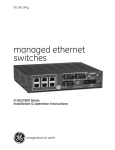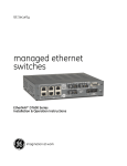
1
WATERS NETWORK SYSTEMS™ OPERATING MANUAL ProSwitch Secure – MS1007 8-Port Classroom and Workgroup Switches CORPORATE HEADQUATERS 5001 American Blvd. W., Suite 605 Bloomington, MN 55437 Phone: 800.441.5319 Phone: 952.831.5603 Fax: 952.831.5605 MANUFACTURING/CUSTOMER SERVICE th 945 37 Avenue, NW Rochester, MN 55901 Phone: 800.328.2275 Phone: 507.252.1951 Fax: 507.285.1952 Web site: http://www.watersnet.com TABLE OF CONTENTS 1.0 SPECIFICATIONS ................................................................................................................ 4 2.0 PACKAGE CONTENTS - PROSWITCH SECURE-MS1007 ............................................. 6 2.1 PRODUCT DESCRIPTION................................................................................................... 6 2.2 LOCATION OF THE PROSWITCH MS1007 ........................................................................ 6 3.0 CONNECTING THE PROSWITCH MS1007 TO YOUR NETWORK ................................... 6 3.1 MOUNTING THE PROSWITCH-MS1007............................................................................. 7 3.2 POWERING THE PROSWITCH-MS1007 ............................................................................ 7 4.0 STATUS OF LEDS................................................................................................................ 7 5.0 BASIC FUNCTIONS ............................................................................................................. 8 5.1 UNICAST SWITCHING......................................................................................................... 8 5.2 MULTICAST SWITCHING .................................................................................................... 8 5.3 VLAN CLASSIFICATION ...................................................................................................... 8 5.4 VLAN FUNCTIONS............................................................................................................... 9 5.5 VLAN CONFIGURATION.................................................................................................... 10 5.6 GVRP .................................................................................................................................. 10 5.7 IGMP ................................................................................................................................... 11 6.0 SWITCH MANAGEMENT CONNECTIONS ....................................................................... 11 7.0 POWER UP PROCEDURES .............................................................................................. 11 8.0 MANAGEMENT FUNCTIONS ............................................................................................ 12 8.1 MANAGEMENT ACCESS OVERVIEW .............................................................................. 12 8.2 CONSOLE ACCESS........................................................................................................... 13 8.3 MODEM ACCESS............................................................................................................... 14 8.4 WEB MANAGEMENT ACCESS ......................................................................................... 14 8.5 SNMP MANAGEMENT ACCESS ....................................................................................... 14 8.6 PROTOCOLS...................................................................................................................... 15 8.7 MANAGEMENT ARCHITECTURE ..................................................................................... 15 9.0 MENU DRIVEN CONSOLE MANAGEMENT ..................................................................... 15 9.1 PERFORMING BASIC MANAGEMENT FUNCTIONS....................................................... 16 9.1.1 LAN PORT CONFIGURATIONS..................................................................................... 17 9.1.2 SPEED AND FLOW CONTROL...................................................................................... 17 9.1.3 ADMIN CONTROL .......................................................................................................... 17 9.1.4 PHYSICAL PORT ADDRESS ......................................................................................... 18 9.2 CONSOLE PORT CONFIGURATIONS.............................................................................. 18 10.0 ADVANCED MANAGEMENT FUNCTIONS.................................................................... 18 10.1 USING THE L2 SWITCHING DATABASE ...................................................................... 19 10.1.1 WORKING WITH VLANS ................................................................................................ 19 10.1.2 ADDING PORTS TO THE VLAN..................................................................................... 20 10.1.3 IP MULTICAST PERSPECTIVE...................................................................................... 20 10.1.4 MAC ADDRESS PERSPECTIVE .................................................................................... 20 10.1.5 PORT PERSPECTIVE .................................................................................................... 20 10.1.6 IP NETWORKING ........................................................................................................... 21 10.1.7 ARP TABLE SETTING .................................................................................................... 21 10.1.8 ROUTING TABLE............................................................................................................ 21 10.1.9 DHCP GATEWAY SETTINGS ........................................................................................ 22 10.1.10 PING SETTINGS ......................................................................................................... 23 10.1.11 BRIDGING ................................................................................................................... 23 10.1.12 STATIC FILTERING .................................................................................................... 23 10.1.13 SPANNING TREE FUNCTIONS ................................................................................. 23 10.1.14 RAPID SPANNING TREE PORT STATES ................................................................. 24 10.1.15 RAPID SPANNING TREE PATH COSTS ................................................................... 24 10.1.16 RAPID SPANNING TREE PRIORITIES ...................................................................... 24 10.1.17 RAPID SPANNING TREE PROTOCOL MIGRATION................................................. 24 10.1.18 RAPID SPANNING TREE EDGE PORT ..................................................................... 24 10.1.19 RAPID SPANNING TREE POINT TO POINT LINK .................................................... 25 2 ProSwitch Secure – MS1007 User’s Manual Page 2 11.0 11.1 11.1.1 11.1.2 12.0 13.0 14.0 14.1 14.1.1 14.1.2 14.1.3 14.1.4 14.1.5 14.1.6 14.1.7 14.1.8 14.1.9 14.1.10 14.1.11 14.1.12 14.1.13 14.1.14 14.1.15 14.1.16 14.1.17 14.1.18 14.1.20 14.1.21 14.2 14.3 14.3.1 14.3.2 14.4 14.4.1 14.4.2 14.4.3 15.0 15.1 15.2 15.3 16.0 SNMP FUNCTIONS ........................................................................................................ 25 OTHER PROTOCOLS .................................................................................................... 25 PORT TRUNKING........................................................................................................... 25 PORT MIRRORING......................................................................................................... 26 DOWNLOADING UPGRADES TO SWITCH .................................................................. 26 ADDITIONAL OPTIONS.................................................................................................. 26 WEB BASED MANAGEMENT ........................................................................................ 27 LOGGING INTO THE SWITCH....................................................................................... 27 OVERVIEW OF THE WEB BROWSER INTERFACE .................................................... 27 USING THE FILE MENU................................................................................................. 27 RECEIVE FILE VIA TFTP ............................................................................................... 27 REBOOT.......................................................................................................................... 28 LOGOUT.......................................................................................................................... 28 BASIC SETUP TASKS .................................................................................................... 28 LAN PORT CONFIGURATION ....................................................................................... 28 CONSOLE PORT CONFIGURATION............................................................................. 29 ADVANCED SETUP CONFIGURATIONS...................................................................... 30 IP NETWORKING ........................................................................................................ 30 GATEWAY SETTINGS ................................................................................................ 31 ARP TABLE ................................................................................................................. 31 DHCP GATEWAY SETTINGS..................................................................................... 31 PER PORT STATISTICS............................................................................................. 31 PORT PRIORITY ......................................................................................................... 31 BRIDGING ................................................................................................................... 31 STATIC MAC FILTER.................................................................................................. 32 VLAN SETTINGS......................................................................................................... 32 SPANNING TREE PERSPECTIVE ............................................................................. 33 RAPID SPANNING TREE BY PORT........................................................................... 33 SNMP .............................................................................................................................. 33 OTHER PROTOCOLS .................................................................................................... 34 PORT TRUNKING........................................................................................................... 34 PORT MIRRORING......................................................................................................... 34 SNMP & RMON MANAGEMENT .................................................................................... 35 SNMP AGENT AND MIB-2 (RFC 1213).......................................................................... 35 RMON GROUPS SUPPORTED ..................................................................................... 35 BRIDGE GROUPS SUPPORTED................................................................................... 36 TROUBLESHOOTING .................................................................................................... 37 BEFORE CALLING FOR ASSISTANCE......................................................................... 37 RETURN MATERIAL AUTHORIZATION (RMA) PROCEDURE .................................... 37 SHIPPING AND PACKAGING INFORMATION .............................................................. 38 WARRANTY .................................................................................................................... 39 2 ProSwitch Secure – MS1007 User’s Manual Page 3 1.0 SPECIFICATIONS OPERATIONAL CHARACTERISTICS: MAC Address Table: 4K MAC Switching Mode: Store and forward Performance: Non-blocking switching architectures Forwarding Rate: 10Mbps: 14,880 pps 100Mbps: 148,800 pps Memory Buffer Size: 2MB Auto-negotiation on TX ports Broadcast storm filter function Auto-MDIX on TX ports MANAGEMENT FEATURES: Web Based, Telnet/TFTP SNMP and RMON Port-based VLAN up to 8 groups ID Tagged VLAN MAC-based trunking Spanning Tree Algorithm IP Multicast filtering through IGMP snooping Port mirroring NETWORK STANDARDS: IEEE 802.3u: 100BASE-TX, 100BASE-FX Fast Ethernet IEEE 802.3: 10BASE-T Ethernet IEEE 802.3x Flow Control IEEE 802.1D IEEE 802.1Q EMI/SAFETY COMPLIANCE: CE & FCC FCC Class A, UL 1950, CSA C22.2 No. 950, EN60950, CE: EN55022 Class A, EN55024 FIBER PORT CHARACTERISTICS: Multimode with SC, ST or MTRJ connectors Speed: 100Base-FX Wavelength: 1300nm Maximum distance: 2km Fiber size: 62.5/125, 50/125 Singlemode with SC connector Speed: 100Base-FX Wavelength: 1300nm Maximum distance: 15/40/75km Fiber size: 8/125, 9/125 NETWORK CABLE CONNECTORS: 10Base-T: CAT3, 4 or 5; up to 100M (328 feet) 100Base-TX: CAT5 or better; up to 100M (328 feet) POWER SUPPLY: Power Input Voltage: 100 to 240V; Internal Power Input Frequency: 50 to 60Hz Power Consumption: 2A, 15W max 2 ProSwitch Secure – MS1007 User’s Manual Page 4 OPERATING ENVIRONMENT: Ambient: 32° to 104°F (0° to 40°C) Storage: -13° to 158°F (-25° to 70°C) Ambient relative humidity: 10% to 90% (non-condensing) MECHANICAL: Enclosure: Rugged high-strength sheet metal suitable for stand-alone, wall or tabletop installation Cooling Method: Convection cooled PHYSICAL CHARACTERISTICS: Dimensions: 10 x 5.3 x 1.25 (254 x 135 x 35cm) Weight: 3.5LBS (1.6kg) 2 ProSwitch Secure – MS1007 User’s Manual Page 5 2.0 Package Contents - ProSwitch Secure-MS1007 Examine the shipping container for obvious damage prior to installing this product. Notify the carrier of any damage that you believe occurred during shipment. Ensure that the items listed below are included. The ProSwitch Secure-MS1007 package contains the following: 8 port switch AC power cord Console cable 2.1 Product Description A switch can be used to overcome the hub-to-hub connectivity limitations as well as improve overall network performance. Switches make intelligent decisions about where to send network traffic based on the destination address of the packet. As a result, the switch can significantly reduce unnecessary traffic. The ProSwitch- Managed models provide 10/100Base-TX ports with an optional 100Base-FX port in a cost effective pocket size package. The 10/100Base-TX ports auto negotiate speed and duplex modes. 2.2 Location of the ProSwitch MS1007 The MS1007 can be installed quickly and easily. However, for an installation with minimum impact on the existing network, please read the following information carefully. Installing the ProSwitch MS1007 involves three steps: 1. Choosing a location 2. Supplying power 3. Connecting the switch Consider the following criteria when selecting a location for the switch: Avoid dusty locations Avoid electromagnetic noisy areas, such as locations close to power transformers or radio transmitters Avoid temperatures below 32° to 104°F (0° to 40°C) Allow sufficient space for proper ventilation Allow a clear view of the front panel LED indicators Allow easy access to the front panel ports and the rear panel switches The power outlet should be within six feet (1.8m) of the switch 3.0 Connecting the ProSwitch MS1007 to Your Network The ProSwitch has been designed to support all standard Ethernet media types within a single switch unit. The various media types supported along with the corresponding IEEE 802.3 and 802.3u standards and connector types are as follows: Fiber: Speed Media Type Max. Distance Connector Type 100Base-FX Multimode fiber 2km SC, ST or MTRJ Port Speed Half/Full Duplex 100/200Mbps 100Base-FX Singlemode fiber 15, 40 or 75km SC 100/200Mbps 2 ProSwitch Secure – MS1007 User’s Manual Page 6 Copper: 10Base-T CAT3, 4 or 5 100m (328ft) RJ45 10/20Mbps 100Base-TX CAT5 or 5E 100m (328ft) RJ45 100/200Mbps Note: Since all switch ports are auto-sensing for both 10 and 100Mbps, it is recommended that high quality CAT5 cables or above (which work for both 10Mbps and 100Mbps) be used whenever possible in order to provide flexibility in a mixed-speed network. Because the switch supports auto MDI/MDI-X detection, normal straight through cables for both workstation connection and hub or switch connection can be used. All ports are auto MDI/MDI-X, so you can use any of the ports to connect a port on another hub or switch with straight through or crossover cables. 3.1 Mounting the ProSwitch-MS1007 Table-Top or Shelf Mounting The ProSwitch MS1007 can be easily mounted on a table-top or any suitable horizontal surface. There are four rubber feet provided for stability so finished surfaces won’t be scratched. 3.2 Powering the ProSwitch-MS1007 The MS1007 switch is equipped with a universal power adapter that accepts AC input voltages from 100 to 240VAC and 50 to 60 Hz. To supply power to your switch: 1. Plug the connector of the power cord into the power port on the rear panel of your switch. 2. Plug the power adapter into an AC wall outlet. 3. Set the power switch to ON and verify that the Power LED is lit. If it is not, check the following: The power switch is in the ON position. The power cord is properly connected to the wall outlet and to the power connection on the switch. The wall outlet is functional. Note: Network cable segments can be connected or disconnected from the switch while the power is on, without interrupting the operation of the switch. 4.0 Status of LEDs LED Power STATUS ON CONDITION Switch is receiving power. Link / Act ON Port has established a valid link. Flashing Data packets are being received or sent. 2 ProSwitch Secure – MS1007 User’s Manual Page 7 5.0 Basic Functions In general, the switch is responsible for switching both VLAN tagged and untagged frames from a receiving port to one or more transmitting ports. The switch performs the following steps during the switching process: VLAN Classification Learning Filtering Forwarding Aging Below is additional information about tasks that the switch performs during unicast and multicast switching: 5.1 Unicast Switching VLAN Classification When the switch receives a frame, it classifies the frame in one of two ways: If the frame is untagged, the switch classifies the frame to an associated VLAN. If the frame is tagged, the switch uses the tagged VLAN ID to identify the broadcasting domain of the frame. Learning After VLAN classification, the switch checks the <source MAC address, VLAN> pair in the switching database (SDB) to see whether the <source MAC address, VLAN> pair is known. If it is unknown, the switch inserts the <source MAC address, VLAN> into the SDB and learns the <source MAC address, VLAN>. If it is known, the switch checks the <source MAC address, VLAN> for a mismatched port ID. If the port ID associated with the <source MAC address, VLAN> pair in the SDB is different than the receiving port, the switch modifies the port ID in the SDB and modifies its management database (MDB) accordingly. Filtering After learning the address, the switch checks to see if the: Source port or destination port is in the forwarding state Source MAC address or destination MAC address is to be filtered Source port ID is the same as destination port ID Forwarding During the forwarding process, the switch checks to see if the <destination MAC address, VLAN> pair is unknown. If it is unknown, the switch floods the receiving frame to all ports in the VLAN, excluding the source port. If it is known, the switch forwards the receiving frame to the port associated with the <destination MAC address, VLAN> pair. At the same time, the switch ascertains the individual’s port’s VLAN tagging/untagging configuration and corresponding VLAN ID to render the appropriate frame tagging when the frame is ready to be transmitted. 5.2 Multicast Switching For multicast switching, the switch checks to see if the received frame is a BPDU. If a BPDU is received, the switch forwards the frame to the CPU for processing by the spanning tree protocol. Otherwise, the switch performs the following processes: 5.3 VLAN classification The VLAN classification is the same as for unicast switching. Learning Learning is the same as for unicast switching. 2 ProSwitch Secure – MS1007 User’s Manual Page 8 Filtering After learning the address, the switch checks to see if the: Source port or destination port is not in the forwarding state. Source MAC address or destination MAC address is to be filtered. Source port ID is the same as destination port ID Forwarding The switch floods the received multicast frame to all ports that are in forwarding state within the VLAN, excluding the source port. At the same time, the switch ascertains the individual port’s VLAN tagging/untagging configuration and corresponding VLAN ID to render the appropriate frame tagging when the frame is ready to be transmitted. Aging The switch performs the aging process for the <MAC addresses, VLAN> pair in the switching database. Once a <MAC address, VLAN> pair is aged out, the SDB is modified. Spanning Tree The switch supports one Spanning Tree per bridged network. 5.4 VLAN Functions A virtual LAN (VLAN) is a network of computers that behave as if they are connected to the same wire, even though they may actually be physically located on different segments of a LAN. VLANs are analogous to a group of workstations, perhaps on multiple physical LAN segments, that are not constrained by their physical location and can communicate as if they were on a common LAN. VLANs are configured through software rather than hardware, which makes them extremely flexible. One of the biggest advantages of VLANs is that when a computer is physically moved to another location, it can stay on the same VLAN without any hardware reconfiguration. Because VLANs are not limited by the hardware constraints that physically connect traditional LAN segments to a network, they can define a network into various logical configurations. For example, VLANs can define a network by application. In this scenario, you might create one VLAN for multimedia users and another for email users. VLANs can also define a network by department or physical layout of the building. For example, you could have one VLAN for the Media Center and another one for Administrative users. As these examples show, VLANs offer unparalleled flexibility. The following sections describe how deploying VLANs can benefit your organization and reduce administration costs. Broadcast Containment In traditional networks, traffic broadcasts to all network devices, whether they are the intended recipients or not. However, VLANs can be set up to contain only those devices that need to communicate with each other. As a result, VLANs significantly reduce network congestion. In addition, VLANs prevent broadcast storms from causing network meltdown due to volumes of traffic. Multicast-Based Multimedia Applications Multimedia applications, such as interactive training, video conferencing, and news-video transmissions, require large amounts of bandwidth. These applications are also extremely sensitive to variable delays, which are unavoidable on a shared Ethernet network. By defining a VLAN based on the IP multicast address for all subscribing members on the VLAN, sufficient bandwidth will be available for these application, providing true multimedia on Ethernet. 2 ProSwitch Secure – MS1007 User’s Manual Page 9 Enhanced Security Because VLANs are self-contained, only the devices within the same VLAN can communicate with each other. If a device in one VLAN wants to communicate with a device in another VLAN, the traffic must go through a router. VLAN Membership VLAN implementation allows: Up to 64 VLANs in one switch. VLANs across multiple switches by using explicit or implicit tagging and the GARP/GVRP protocol defined in IEEE802.1p and 802.1Q. A workstation’s network interface card to belong to multiple VLANs. A switch port to be associated with multiple VLANs. Definitions of VLAN Membership VLAN implementation allows VLAN membership to be defined based on ports. Port-based VLANs are organized by physical port number. For example, switch ports 1, 2, 4 and 6 can be grouped on VLAN, while server ports 3, 5, 7 and 8 can be on another VLAN. Broadcasts from servers within each group would only go to the members of its own VLAN. This ensures that broadcast storms cannot cause a network meltdown due to volumes of traffic VLAN Membership Learning A port-based VLAN is defined as using a static binding between a VLAN and its associated ports. The switch’s forwarding decision is based on the destination MAC address and its associated port ID. Therefore, to make valid forwarding and flooding decisions, the switch learns the relationship of the MAC address to its related port – and thus to the VLAN – at runtime. Remote VLAN Learning The switch supports GVRP (Group VLAN Registration Protocol) which allows dynamic registration of VLAN port members within switch and across multiple switches. 5.5 VLAN Configuration The switch provides a Local/Remote Management Console Interface for VLAN configuration and management. An SNMP-based VLAN MIB is also provided. Intra-VLAN Communication The switch supports intra-VLAN communication through hardware, as described in the VLAN section. Inter-VLAN Communication The switch supports inter-VLAN communication using CPU-based routing software. 5.6 GVRP In addition to network management tools that allow network administrators to statically add and delete VLAN member ports, the routing switch supports GVRP. GVRP supports dynamic registration of VLAN port members within a switch and across multiple switches. In addition to dynamically updating registration entries within a switch, GVRP is used to communicate VLAN registration information to other VLAN-aware switches, so that members of a VLAN can cover a wide span of switches on a network. GVRP allows both VLAN-aware workstations and switches to issue and revoke VLAN memberships. VLAN-aware switches register and propagate VLAN membership to all ports that are part of the active topology of the VLAN. 2 ProSwitch Secure – MS1007 User’s Manual Page 10 5.7 IGMP The Internet Group Management Protocol (IGMP) runs between hosts and their immediately neighboring multicast routers. The protocol’s mechanisms allow a host to inform its local router that it wants to receive transmissions addressed to a specific multicast group. Routers periodically query the LAN to determine if known group members are still active. If there is more than one router on the LAN performing IP multicasting, one of the routers is elected “querier” and assumes the responsibility of querying the LAN for group members. Based on the group membership information learned from the IGMP, a router can determine which (if any) multicast traffic needs to be forwarded to each of its “leaf” subnetworks. Multicast routers use this information, along with a multicast routing protocol, to support IP multicasting across the Internet. IGMP provides the final step in an IP multicast packet delivery service since it is only concerned with the forwarding of multicast traffic from the local route to group members on directly attached subnetworks. Routing switches support IP Multicast Filtering by: Passively snooping on the IGMP Query and IGMP Report packets transferred between IP Multicast Routers and IP Multicast host groups to learn IP Multicast group members, and Actively sending IGMP Query messages to solicit IP Multicast group members. The purpose of IP multicast filtering is to optimize a switched network’s performance, so multicast packets will only be forwarded to those ports containing multicast group hosts members and routers instead of flooding to all ports in the subnet (VLAN). Routing switches with IP multicast filtering/switching capability not only passively monitor IGMP Query and Report messages, DVMRP Probe messages, PIM, and MOSPF Hello messages; they also actively send IGMP Query messages to learn locations of multicast routers and member hosts in multicast groups within each VLAN. Note: IGMP neither alters nor routes any IP multicast packets. Since IGMP is not concerned with the delivery of IP multicast packets across subnetworks, an external IP multicast router is needed if IP multicast packets have to be routed across different subnetworks. 6.0 Switch Management Connections Administration console via RS-232 serial port The switch provides an onboard serial port, which allows the switch to be configured via a directly connected terminal or a Telnet session. Web-based browser interface The switch also boasts a point-and-click browser-based interface that allows users to access full switch configuration and functionality from a Netscape or Internet Explorer browser. External SNMP-based network management application The switch can also be configured via SNMP. For additional information on switch management, refer to Section 8.0. 7.0 Power Up Procedures The switch performs its Power-On Self Test (POST) when the power is switched on. During the POST, the switch CPU will: Perform a series of diagnostic procedures to make sure the basic system is functioning properly 2 ProSwitch Secure – MS1007 User’s Manual Page 11 Decompress the main switching software runtime image from the flash ROM into DRAM (dynamic random access memory) Begin executing the main switching software When you press the Escape (Esc) key on a terminal connected to the switch during the POST process, a command line will display the prompt Boot>. You can execute the following options: Download runtime software from serial port0 This will download the runtime system image to the switch via the serial port. Before selecting this option, make sure: A host system is running a terminal emulation program that supports the Kermit file transfer protocol. The host system’s hard drive has the required binary file that will be downloaded to the switch. Configure the system This option lets you modify any configurable parameter in the switch’s flash ROM before the switch system boots. Run manufacturing diagnostics This option is to download the manufacturer’s diagnostics. Refer to Download Runtime Software for download requirements. When the file transfer is completed, the target system jumps to the entry point of the diagnostic program and starts executing the diagnostic code. The Main Menu of the diagnostic program is displayed which allows you to initiate tests or obtain system information. User intervention is not required when a test runs, unless an error occurs. If an error occurs during testing, you are given the choice of continuing the diagnostics or skip the error. 8.0 Management Functions This section explains the available choices for management access to the switch. It describes the types of management applications and the communication and management protocols that deliver data between your management device (workstation or personal computer) and the system. It also contains information about port connection options. The following topics are covered in this section: Management Access Overview Guidelines for Implementation Administration Console Access Web Management Access SNMP Access Standards, Protocols, and Related Reading 8.1 Management Access Overview The switch gives you the flexibility to access and manage the switch using any or all of the following methods. The administration console and web browser interface support are embedded in the switch software and are available for immediate use. Administration Console via RS-232 Serial Port Advantages No IP address or subnet needed 2 ProSwitch Secure – MS1007 User’s Manual Page 12 Text-based Telnet functionality and HyperTerminal built into Windows 95/98/NT/2000 operating systems Disadvantages Must be near switch or use dial-up connection Inconvenient for remote users Modem connection may prove to be unreliable or slow Web-based browser interface Advantages Ideal for configuring the switch remotely Compatible with all popular browsers Can be accessed from any location Most visually appealing Disadvantages Security can be compromised (hackers need only know the IP address and subnet mask) May encounter lag times on poor connections External SNMP-based Network Management Application Advantages Communicates with switch functions at the MIB level Based on open standards Disadvantages Requires SNMP manager software Least visually appealing of all three methods Some settings require calculations Security can be compromised (hackers need only know the community name) 8.2 Console Access The administration console is an internal, character-oriented, menu-driven user interface for performing system administration such as displaying statistics or changing option settings. Using this method, you can view the administration console from a terminal, personal computer, Macintosh or workstation connected to the switch’s console port. There are two ways to use this management method: direct access or modem access. The following sections describe these methods. Direct Access Direct access to the administration console is achieved by directly connecting a terminal or a PC equipped with a terminal-emulation program (such as HyperTerminal) to the switch console port. When using the management 2 ProSwitch Secure – MS1007 User’s Manual Page 13 method, configure the terminal-emulation program to use the following parameters (you can change these settings after login): Default parameters Bits per second: 115,200bps Data bits: 8 Parity: None Stop Bits: 1 Flow control: None This management method is often preferred because you can remain connected and monitor the system during system reboots. Also, certain error messages are sent to the serial port, regardless of the interface through which the associated action was initiated. A Macintosh or PC attachment can use any terminal-emulation program for connecting to the terminal serial port. A workstation attachment under UNIX can use an emulator such as TIP. Note: Turn on switch after accessing the Hyper Terminal screen. 8.3 Modem Access You can access the switch’s administration console from a PC or Macintosh using an external modem attached to the console port. The switch management program provides the Console Port screen, accessible from the Basic Management screen, which allows you to configure parameters for modem access. When you have configured the external modem from the administration console, the switch transmits the characters that you have entered as output on the modem port. The switch echoes characters that it receives as input on the modem port to the current administration console session. The console appears to be directly connected to the external modem. 8.4 Web Management Access The switch provides a browser interface that allows you to configure and manage the switch remotely. After you set your IP address for the switch, you can access the switch’s web interface applications directly in your web browser by entering the IP address of the switch. You can then use your web browser to list and manage switch configuration parameters from one central location, just as if you were directly connected to the switch’s console port. Web Management requires either Microsoft Internet Explorer 4.01 or later or Netscape Navigator 4.03 or later. Netscape Navigator - If you use Netscape Navigator 4.03 or 4.04, install the Netscape JDK 1.1 Patch. Download the patch from: http://help.hetscape.com/filelib.html#smartupdate If you encounter problems accessing Help files when you use Netscape, clear the browser memory cache and disk cache, and restart the browser. Internet Explorer - If you use Internet Explorer, install the latest 4.01 Service Pack 1. This service pack makes Internet Explorer Year 2000 compliant and fixes other product-support issues. Download the 4.01 Service Pack 1 from the following location: http://www.microsoft.com/msdownload/iebuild/ie4sp1_win32/en/ie4sp1_win32.htm If the above link is unavailable, download the service pack from the Microsoft home page: http://www.microsoft.com. 8.5 SNMP Management Access You can use an external SNMP-based application to configure and manage the switch. This management method requires the SNMP agent on the switch and the SNMP Network Management Station to use the same community string. This management method, in fact, uses two community strings: the get community string and the set community string. If the SNMP Network management station only knows the set community string, it can read and 2 ProSwitch Secure – MS1007 User’s Manual Page 14 write to the MIBs. However, if it only knows the get community string, it can only read MIBs. The default get and set community strings for the switch are public. 8.6 Protocols The switch supports the following protocols: Virtual Terminal Protocols, Such as Telnet A virtual terminal protocol is a software program, such as Telnet, that allows you to establish a management session from a Macintosh, a PC, or a UNIX workstation. Because Telnet runs over TCP/IP, you must have at least one IP address configured on the switch before you can establish access to it with a virtual terminal protocol. Note: Terminal emulation is different from a virtual terminal protocol in that you must connect a terminal directly to the console port. Simple Network Management Protocol (SNMP) SNMP is the standard management protocol for multi-vendor IP networks. SNMP supports transaction-based queries that allow the protocol to format messages and to transmit information between reporting devices and data-collection programs. SNMP runs on top of the User Datagram Protocol (UDP), offering a connectionless-mode service. 8.7 Management Architecture All of the management application modules use the same Messaging Application Programming Interface (MAPI). By unifying management methods with a single MAPI, configuration parameters set using one method (e.g. console port) are immediately displayed the other management methods (e.g. SNMP agent of web browser). The management architecture of the switch adheres to the IEEE open standard. This compliance assures customers that the switch is compatible with and will interoperate with other solutions that adhere to the same open standard. 9.0 Menu Driven Console Management The switch provides a menu-driven console interface for configuration purposes. The switch can be configured either locally through its RS-232 port or remotely via a Telnet session. This section describes the configuration procedure using the menu-driven console. Logging Into the Switch 1. Access Hyper Terminal using the default parameters listed under Section 8.2 Console Access. 2. Turn on the switch. 3. At the screen prompt, type admin for the switch console login. 4. There is no factory set password, so press Enter at the prompt for the password. Note: Only one console and three telnet users can log on to the switch concurrently. However, it is not recommended that multiple users modify the configuration at the same time. When you login to the switch, the following menu options will be available: Basic Management Basic configuration settings such as setting ports for speed and duplex, set system name, controlling flow control, etc. can be made from this option. Advanced Management Advanced management functions such as IP Networking, Bridging, Spanning Tree, etc. can be made from this option. 2 ProSwitch Secure – MS1007 User’s Manual Page 15 Logout Use this option to logout when you have made your configurations. Save Settings Use this option to save the current settings and remain in the configuration program. Restore Default Settings Use this option to restore the factory default settings. Reboot Use this option to reboot the switch. Navigating Through the Console Interface The console interface consists of a series of menu choices. Each menu choice has several options, which are listed vertically. Move the cursor to highlight an option, and press Enter select that option. Press this key… To Up Arrow or k* Move the highlight one line up in a menu box Down Arrow or j* Move the highlight one line down in a menu box Tab Move the highlight between screens Enter Select the highlighted option Esc Move to a previous menu Note: The< K> and <J> keys won’t move if the <Caps Lock> key is locked. 9.1 Performing Basic Management Functions Basic management activities consist of General, LAN Port, and Console Port tasks. 1. Highlight Basic Management from the Switch Management screen and press Enter. The Basic Management screen will be displayed. 2. Highlight a desired option and press Enter. 3. The bottom line of each menu screen displays the keys to use to move through the menus. Esc will take you back to the previous menu. General Management Configurations Use the basic management functions to set the following options: System name Location Set admin password – no password by default Set guest password 2 ProSwitch Secure – MS1007 User’s Manual Page 16 Enable statistics collection – disabled by default Enable or disable re-boot error - disabled by default Enable or disable Telnet – enabled by default Remote HTTP Login – enabled by default 9.1.1 LAN Port Configurations The LAN port configuration menu allows you to set the following options: Speed and flow control Speed options Full duplex or half duplex View physical port address Port up or down 9.1.2 Speed and Flow Control To configuration the LAN ports: 1. Highlight LAN Port from Basic Management Menu and press Enter. 2. Speed & Flow Control will be highlighted. Press Enter. 3. Highlight Desired Ports and press Enter to configure all ports at one time. Or, move to highlight each port and press Enter. 4. The Port Setting Option screen will be displayed. Highlight Speed & Flow Control and press Enter. 5. For Line Speed, highlight Auto next to Line Speed and press Enter. Note: The available choices are 10M HD, 10M FD, 100 HD, or 100 FD. HD denotes half-duplex and FD denotes full-duplex. This option allows you to hard set a port if the connected device requires a set speed and duplex setting. 6. Press Esc to return to the previous screen. 7. Highlight Flow Control and press Enter. 8. Flow control can be set at Auto, On or Off. (Flow control is ON by default.) Highlight your choice and press Esc to return to the previous screen. 9. Press Esc to return to the Basic Management menu. 9.1.3 Admin Control Admin control allows you to turn off a port. All ports are up by default. 1. Highlight LAN Port and press Enter. 2. Highlight Speed and Flow Control and press Enter. 3. Highlight the Desired Port and press Enter. 4. Highlight Admin Control and press Enter. 5. Select Up or Down and press Enter. 6. Press Esc to return to the LAN Port Configurations menu. 2 ProSwitch Secure – MS1007 User’s Manual Page 17 9.1.4 Physical Port Address 1. Highlight Physical Address from the LAN Port Configuration menu and press Enter. 2. View physical port address and make note if necessary. 3. Press Esc to return to the Basic Management menu. 9.2 Console Port Configurations 1. From the Basic Management menu, highlight Console Port and press Enter. 2. To change the current console baud rate, highlight Baud Rate and press Enter. 3. To change the current flow control method, highlight Flow Control and press Enter. 4. Choose between Disabled, TRS/CTS, XON/XOFF. Flow control is disabled by default. 5. Press Esc after making selection. 6. To select the console modem control connection, highlight Modem Control and press Enter for “Modem Control.” 7. Select Disabled or Enabled. 8. If the Modem Control is enabled you may choose the Modem Setup String. Highlight Modem Setup String and press Enter. Choose Default or Custom Setup String. Note: The Default Setup String configures the modem to auto answer. It will work for all Hayes compatible modems. 7. Highlight SLIP and press Enter to select Disabled or Enabled. If you enable SLIP, you will receive a warning. The console port will become accessible only thru the SLIP protocol. 8. To enter a SLIP IP Address, highlight SLIP Address and press Enter. Enter the IP Address. 9. Highlight, SLIP Subnet Mask, and enter the Subnet Mask. Note: You must enter a SLIP address before you can enter a SLIP subnet mask. 10. Press Esc to return to the Basic Management menu. 10.0 Advanced Management Functions Advanced management functions consist of the following: L2 Switching Database - View and change VLAN, MAC address, IP multicast group, and port perspectives. IP Networking – View and change IP settings, ARP and routing table parameters, DHCP gateway settings and ping settings. Bridging – View and change the aging period for a MAC address and the flood limit for all ports. Static Filtering – View, add, delete and search all source or destination MAC addresses to be filtered. Spanning Tree – View and change spanning tree configurations, port states, path costs and port priorities. SNMP – View and change SNMP configuration. Other Protocols – View and change GVRP and IGMP settings. Port Trunking – Assign a range of ports to trunking groups. Port Mirroring – Mirror one port to Port 1. 2 ProSwitch Secure – MS1007 User’s Manual Page 18 File Transfer – Send files using the TFTP or Kermit protocol. 10.1 Using the L2 Switching Database 10.1.1 Working with VLANs 1. Select L2 Switching Database from the Advanced Management and press Enter. 2. The following screen will be displayed: 4. The first option is VLAN Perspective. Press Enter to view the default VLAN information. Note: The IEEE802.1Q standard defines VLAN ID #1 as the default VLAN. The default VLAN includes all of the ports as the factory default. The default VLAN’s egress rule restricts the ports to be all untagged, so it can by default, be easily used as a simple 802.1D bridging domain. The default VLAN’s domain shrinks as untagged ports are defined in other VLANs. 5. To create a VLAN, highlight VLAN Perspective and press Enter. 6. Press + (the plus key) to enter New VLAN Settings. Note: “Remote” is appended to the VLAN ID automatically if the VLAN is learned from a remote switch. 7. Press Enter to enter the new VLAN ID. 8. Press Enter when finished. 9. Highlight the VLAN Name and press Enter. 10. Press Esc. The following screen appears: 11. Press + to add switch ports to the newly created VLAN. 2 ProSwitch Secure – MS1007 User’s Manual Page 19 12. Highlight the desired option from Port Options and press Enter. 13. From Select Untagged Ports, press Enter to select all ports or highlight ports individually, and press Enter. 14. Repeat these steps if you want to add tagged or forbidden ports. 15. Press Esc to return to the VLAN ID screen. 16. To delete a VLAN, highlight a VLAN and press – (the minus key) to delete the VLAN. Select Yes to confirm. Note: You cannot delete the default VLAN. 17. Press Esc to return to the previous screen. 18. To view VLAN information, highlight the VLAN and press Enter. 19. Highlight VLAN Activities and press Enter. 20. Press Esc to return to the previous screen. 10.1.2 Adding Ports to the VLAN 1. Highlight an existing VLAN and press Enter to view VLAN information. 2. Highlight VLAN Activities and press Enter to view or search activity information. 3. Press Esc to return to the previous screen. 4. Highlight VLAN Settings and press Enter. The next screen allows you to add or delete ports to the VLAN. 5. Use the keys displayed at the bottom of the screen to add or delete ports. 6. Return to the L2 Switching Database menu. 10.1.3 IP Multicast Perspective Note: If IGMP is disabled, you cannot view the IP Multicast Group Perspective. IGMP is disabled by default. 1. Highlight IP Multicast Group Perspective from the L2 Switching Database Menu and press Enter. 2. Highlight an address to view information associated with this IP multicast group and press Enter. 3. Return to the L2 Switching Database menu. 10.1.4 MAC Address Perspective 1. Highlight MAC Address Perspective from the L2 Switching Database and press Enter. 2. Enter a MAC Address to view characteristics information, corresponding VLANs and corresponding ports in the switching database. 10.1.5 Port Perspective The Port Perspective will allow you to view VLAN activities and RMON statistics. 1. Highlight Port Perspective from the L2 Switching Database and press Enter. 2. Highlight Per Port VLAN Activities and press Enter. 3. Highlight a port and press Enter. 4. View or search by MAC address individually. 5. Press Esc to return to the Port Perspective menu. 6. Highlight Per Port Statistics and press Enter. 2 ProSwitch Secure – MS1007 User’s Manual Page 20 7. Highlight a port and press Enter. View statistics. 8. Press R to reset counter for this port. 9. Press Esc to return to the Port Perspective menu. 10. Highlight Per Port Priority and press Enter. 11. Highlight a port and press Enter. View corresponding priority level. 10.1.6 IP Networking 1. From the Advanced Management menu, highlight IP Networking and press Enter. 2. Highlight IP & RIP Settings and press Enter. 3. The current list of VLAN IDs, addresses, subnet masks, proxy ARPs and RIPs will be displayed. 4. Highlight the row that contains the parameters you want to modify, and press Enter. 5. Enter the IP Address. 6. Set the desired configurations. 7. Press Esc to return to the IP Networking menu. 10.1.7 ARP Table Setting 1. Highlight ARP Table from the IP Networking menu and press Enter. This screen displays the ARP table entries that have been defined or learned. 2. Press + to add an entry into the ARP table. Enter the Internet/Physical Addresses. 3. Press – to delete a static entry from the ARP Table. Note: No precautionary message appears before you delete an entry from the ARP table. Be sure you want to delete it before doing so. 4. Press S to search a static entry. You can search by Internet address or physical address. 10.1.8 Routing Table 1. Highlight Routing Table from the IP Networking menu and press Enter. This screen allows you to view, add, delete or search a particular routing path. 2. Press + to enter Route Options. Select Default Gateway or Static Route. 3. Press – to delete an entry in the routing table. 4. Press S to search a network address. Enter the desired network address. Note: No precautionary message appears before you delete an entry from the routing table. Be sure you want to delete it before doing so. 2 ProSwitch Secure – MS1007 User’s Manual Page 21 The routing table displays the following information. Column Network Mask Gateway The IP sub network address to which the switch can route packets. The related IP sub network mask to which the switch can route packets. The IP address of the router at the next hop. Metric The number of hops needed between the switch and the destination network. VLAN The VLAN within which the gateway or destination resides. Type The IP route type for the IP sub network. There are six IP route types: Protocol 10.1.9 Description Direct A directly connected sub network. Remote A remote IP sub network or host address. Myself A switch IP address on a specific IP sub network. Bcast A sub network broadcast address. Mcast An IP multicast address. Martian An illegal IP address to be filtered. Indicates one of the following: Local A manually configured routing entry. NetMgmt A routing entry set via SNMP. ICMP A routing entry obtained via ICMP redirect. RIP A routing entry learned via the RIP protocol. Other A protocol other than one of the other four listed above. DHCP Gateway Settings 1. Return to the Advanced Management menu. Note: You must have a VLAN setup to use the DHCP Gateway Settings. 2. Highlight IP Networking and press Enter. 3. Highlight DHCP Gateway Settings and press Enter. 4. Highlight the VLAN you want to change and press Enter. 5. Press + on keypad to add a relay IP. Choose a suitable interface or All Interfaces from Select Outbound Relay Interfaces. 6. Press – to delete a relay IP. Note: No precautionary message appears before you delete a relay IP. Be sure you want to delete it before doing so. 7. Highlight DHCP Gateway and press Enter. Select Disable or Enable. 8. Highlight Maximum Hops and press Enter. 9. Enter decimal number (1-16) to configure the maximum number of hops. 10. Highlight Delay and press Enter. 11. Enter decimal number (0-65535) to configure the delay in seconds. 12. Highlight Preferred Server and press Enter. 13. Enter IP address for the Preferred Server. 14. You may specify up to three more Preferred Servers by repeating the above steps. 2 ProSwitch Secure – MS1007 User’s Manual Page 22 10.1.10 Ping Settings 1. Return to the IP Networking menu. 2. Highlight Ping and press Enter. 3. Highlight Host and press Enter. 4. Enter 4 decimal bytes (dot separated) as the IP address to ping. 5. Highlight Count and press Enter. 6. Highlight Size and press Enter. 7. Specify a packet count number from 1 to 999, or type 0 for an infinite packet count. Press Enter. 8. Highlight Size and press Enter. 9. Specify a packet size from 0-1500 and press Enter. 10. Highlight Timeout and press Enter. 11. Specify a timeout value from 1-999 and press Enter. 12. Press Esc to begin Ping when you have entered the ping parameters. 10.1.11 Bridging 1. Highlight Bridging from the Advanced Management menu and press Enter. 2. Highlight Aging Time and press Enter. 3. Make a choice between Set Aging Time and No Aging. 4. If you set aging, you will be required to enter an aging period in second. 5. Highlight Flood Limit for all Ports and press Enter. Enter a decimal number as flood limit in packets per second or choose Unlimited. 10.1.12 Static Filtering 1. Highlight Static Filtering from the Advanced Management menu and press Enter. 2. Highlight Source MAC Address or Destination MAC Addresses for static filtering and press Enter. 3. Press + to add a specific MAC address to be filtered. 4. Enter the MAC Address. 5. Press – to delete a specific MAC address from being filtered 6. Press S to search through the current list of MAC addresses in the static filtering database. The static filtering database maximum capacity is 64. Note: No precautionary message appears before you delete a specific MAC address from being filtered. Be sure you want to delete it before doing so 10.1.13 Spanning Tree Functions 1. Highlight Rapid Spanning Tree from the Advanced Management menu. 2. Select Spanning Tree Configurations. 3. Choose Disabled or Enabled next to Spanning Tree Protocol. 4. Highlight Bridge Priority and press Enter. 2 ProSwitch Secure – MS1007 User’s Manual Page 23 5. Enter a decimal number for the bridge priority and press Enter. 6. Highlight Hello Time and press Enter. 7. Enter a decimal number for the Hello Time and press Enter. 8. Highlight Max Age and press Enter. (Move cursor down to see the remaining configurations for Spanning Tree.) 9. Highlight Forward Delay and press Enter. Enter the delay in seconds. 10. Highlight STP Version and press Enter. Make a choice between STP Compatible and RSTP. 11. Highlight Tx Hold Count and press Enter. 12. Enter a decimal number and press Enter 13. Highlight Path Cost Default and press Enter. 14. Make a choice between 16-bit or 32-bit. 15. Return to the Spanning Tree Protocol menu. 10.1.14 Rapid Spanning Tree Port States 1. Highlight Spanning Tree Port States if you want to change per port administration status and press Enter. 2. Highlight a port if you want to change its administration status and press Enter. 3. Choose between Disabled and Enabled for RSTP function. 4. Return to the Spanning Tree Protocol menu. 10.1.15 Rapid Spanning Tree Path Costs 1. To change the path cost, highlight Rapid Spanning Tree Path Costs and press Enter. 2. Highlight All Ports or each port individually and press Enter. 3. For a new path cost, type a decimal number and press Enter. 4. Return to the Spanning Tree Protocol menu. 10.1.16 Rapid Spanning Tree Priorities 1. To change the priority level per port, highlight Spanning Tree Port Priorities and press Enter. 2. Highlight All Ports or each port individually and press Enter. 3. For a new priority value, type a decimal from 0-240 and press Enter. A low value provides the port with a greater likelihood of becoming a root port. 4. Return to the Spanning Tree Protocol menu. 10.1.17 Rapid Spanning Tree Protocol Migration 1. To enable the Protocol Migration, highlight Protocol Migration and press Enter. 2. Highlight each port individually and press Enter. Select Enable or disable port migration. 3. Return to the Spanning Tree Protocol menu. 10.1.18 Rapid Spanning Tree Edge Port 1. To enable or disable the edge port level, highlight Edge Port Setting and press Enter. 2. Highlight each port individually and press Enter. 2 ProSwitch Secure – MS1007 User’s Manual Page 24 3. Select Enable or Disable edge port setting. 4. Return to the Spanning Tree Protocol menu. 10.1.19 Rapid Spanning Tree Point to Point Link 1. To change the point to point link, highlight Point to Point Link and press Enter. 2. Highlight each port individually and press Enter. Select enable, disable or auto point to point link setting. 11.0 SNMP Functions 1. Highlight SNMP from the Advanced Management menu and press Enter. 2. Highlight SNMP and press Enter. Select Disabled or Enabled. 3. Highlight Get Community Name and press Enter. 4. Enter the community name and press Enter. 5. Highlight Set Community name and press Enter. 6. Enter the community name. 7. Highlight Trap Community Name 1 and press Enter. 8. Enter the trap community name and press Enter. 9. Highlight Trap Host 1 IP Address and press Enter. 10. Type an IP address for trap host 1 and press Enter. 11. Repeat to specify up to two additional trap host IP addresses. 12. Highlight Cold Start Trap and press Enter. Select Disabled or Enabled. (Press the down arrow key for the remaining configurations.) 13. Highlight Link Down Trap and press Enter. Select Disabled or Enabled. 14. Highlight Link Up Trap and press Enter. Select Disabled or Enabled. 15. Highlight Authentication Failure Trap and press Enter. Select Disabled or Enabled. 16. Highlight Rising Alarm Trap and press Enter. Select Disabled or Enabled. 17. Highlight Falling Alarm Trap and press Enter. Select Disabled or Enabled. 18. Highlight Topology Change Trap and press Enter. Select Disabled or Enabled. 19. Return to the Advanced Management menu. 11.1 Other Protocols 1. Highlight Other Protocols from the Advanced Management menu and press Enter. 2. Highlight GVRP and press Enter. Select Disabled or Enabled. 3. Highlight IGMP and press Enter. Select Disabled or set in either Passive or Active mode. 4. Return to the Advanced Management menu. 11.1.1 1. Port Trunking Highlight Port Trunking from the Advanced Management menu and press Enter. 2 ProSwitch Secure – MS1007 User’s Manual Page 25 2. Highlight a trunk group to which you want to assign ports and press Enter to Select Range. 3. Press Enter to select each trunk port. 4. Press Esc when you have completed the selection of ports to return to the Advanced Management menu. 11.1.2 Port Mirroring 1. Highlight Port Mirroring from the Advanced Management menu and press Enter. You can mirror one port to port 1. 2. Press Enter to access Port Mirroring Options. 3. Press Enter for Mirror To, and press Enter again to list the ports. 4. Press Enter to return to the Port Mirroring Options menu. 5. Highlight Mirror From and press Enter. 6. Highlight the port you want to mirror from and press Enter. 7. Select Mirror Mode. From Mode Options, select receive or transmit for the mirrored port. 8. Press Esc when you have completed making your selections to return to the Advanced Management menu. 12.0 Downloading Upgrades to Switch The TFTP Protocol is used to download upgraded software to the ProSwitch MS1007. In order to access the specified TFTP server, a VLAN with the proper IP address and routing path to the TFTP server must be configured. 1. Highlight File Transfer from the Advanced Management menu and press Enter. 2. Highlight Receive File Via TFTP and press Enter. 3. If the default File Name is not the one you intend to receive, press Enter. Type the name of the file you intend to receive and press Enter. 4. Highlight IP Address and press Enter. Type the IP address from where the file will be obtained. 5. Press Esc when completed. Note: A dialog box will be displayed asking you if you want to transfer the file now. Highlight Yes and press Enter to start the file transfer. Or, highlight No and press Enter to cancel the transfer. Use Esc to exit. 6. Highlight Send File via TFTP and press Enter. 7. If the default File Type is not the one you intend to send, press Enter. Select the correct file type and press Enter. 8. You can also send and receive files via Kermit. 13.0 Additional Options The following options are available from the Main Management Menu: Logout – Use the Logout option to exit switch management. You will be prompted to save your settings before logging out. Save Settings – Use Save Settings to save the current settings and remain in the management menu. 2 ProSwitch Secure – MS1007 User’s Manual Page 26 Restore Default Settings – Use the Restore Default Settings option to restore the factory default settings. The switch will be rebooted after confirming Yes to this option. Reboot – Use this option to reboot the switch. 14.0 Web Based Management The ProSwitch MS1007 provides a web-based browser interface for configuring and managing the switch. This interface allows you to access the switch using a preferred web browser. This section describes the procedures to configure the switch using its web-based browser interface. Refer to Section 10.1.6 for instructions to set the IP. 14.1 Logging into the Switch 1. In your web browser, enter the IP Address of the switch 2. Enter your login ID or the factory default login ID admin. 3. Enter the password. There is no password by factory default. 14.1.1 Overview of the Web Browser Interface The web browser interface provides three point-and-click buttons at the upper field of the screen for configuring and managing the switch. In addition, you can click on any port on the switch image to view the switch’s current speed, duplex, and activity status. The Basic Setup/General parameters appear at the lower field of the screen. These parameters can also be displayed by clicking Basic Setup button and select General in sub-menu. The following lists of an overview of the menu options. File – Use the file menu to save settings configured in the browser interface, download upgraded software via TFTP, reboot the switch and logout of the browser interface. Basic Setup – Use basic setup to perform general, LAN and console port activities. Advanced Setup – The Advanced Setup menu will allow you to perform the following tasks: o MAC Address Management o IP Networking (IP and RIP settings, Routing Tables, ARP Table and DHCP Settings) o View port statistics o Set port priority, bridging, static MAC filters, IP Multicast groups, VLAN configurations, SNMP, port trunking, and port mirroring o Change password 14.1.2 Using the File Menu To save your configuration settings, 1. Click File. 2. Click Save Setting. Use Save setting to save the configurations you have just set and remain in the management screen. 3. Click OK to respond to the message “Are you sure you want to save setting”? Or, click Cancel to abort saving the configurations. 14.1.3 Receive File Via TFTP To download software to the switch, 2 ProSwitch Secure – MS1007 User’s Manual Page 27 1. Click Receive File Via TFTP on the [File] display 2. For File Name, type the name of the file you are downloading. 3. For IP Address, type the IP address from where the file will be obtained. 4. Click Receive Now! Note: The TFTP protocol is used to download upgraded software to the switch. In order to access the specified TFTP server, a VLAN with the proper IP address and routing path to the TFTP server must be configured. 14.1.4 Reboot To reboot the switch, 1. Click on File. 2. Click on Reboot. 3. Click OK to respond to the message “Are you sure you want to save setting”? Or, click Cancel to abort saving the configurations. 14.1.5 Logout 1. Click File. 2. Click Logout. 3. Click OK to respond to the message “Are you sure you want to save setting”? Or, click Cancel to abort saving the configurations. 14.1.6 Basic Setup Tasks The Basic Setup Menu displayed provides a variety of general management options. To perform Basic Setup Activities: 1. Click the Basic Setup button at the upper field of the main display, the menu options appear. 2. Click General and the screen will display Basic Setup/General parameters. This is the same screen you saw first when you accessed the switch browser interface. 3. Click in the System Name text box to enter or replace the current system name. 4. Click in the Location text box to enter or replace the current location name. 5. To enable or disable statistics collection at the switch, click the appropriate choice from the Statistic Collection drop-down menu. 6. To allow or prevent the switch from rebooting when a fatal error is detected, click the appropriate choice from Reboot-On-Error drop-down menu. 7. To enable or disable access to the switch management via Telnet, click the appropriate choice from the Remote Telnet Login drop-down menu. 8. Click Update Setting. A confirmation message will be displayed. 14.1.7 LAN Port Configuration The Basic Setup Menu includes settings for the LAN ports. 1. Click the Basic Setup button. 2. Point to LAN Port and click Speed & Flow Control. 2 ProSwitch Secure – MS1007 User’s Manual Page 28 Note: The information displayed automatically updates every 15 seconds, without requiring you to refresh the window. 3. Point to LAN Port and click Port Configuration. 4. In the Port column, click the port your want to configure. Example, Port 1. 5. Click the drop-down menu under Admin Setting and choose disable or enable. Note: Disable places the port in DOWN state. In this state, packets cannot be switched to and from the port. Enable places the port in UP state. In this state, packets can be switched to and from the port. 6. Click the drop-down menu under Speed/Duplex Options if you want to change the line speed and duplex settings. Note: Auto allows the switch to automatically ascertain the line speed and duplex mode. All the other selections force the ports to use a specific line speed and duplex mode. HD denotes half-duplex mode; FD denotes full-duplex mode. 7. Click the drop-down menu under Flow Control Options if you want to configure the flow control for this port. Note: Auto: allows the switch to automatically ascertain whether or not to use flow control. Disable: turns off flow control at all times. Enable: turns on flow control at all times. 8. Click Update Setting when completed. Note: For your convenience, you may click the LEDs on the image of the switch and view current speed, duplex, and link activity 14.1.8 Console Port Configuration To use the console port configuration: 1. Click the Basic Setup button. 2. Click Console Port. 3. Click an appropriate speed from the Baud Rate drop-down menu. Note: Auto allows the switch to autobaud between 9600bps and 115,200bps. All other selections force a specific console baud rate. 4. Click the Flow Control drop-down menu and make a choice between Disable and Enable. 5. Click the Modem Control drop-down menu and make a choice between Disable and Enable the modem connection to the console port. 6. If you enabled a modem connection to the console port, click in the Modem Setup String drop-down menu choose between Default_Setup_String or Custom_Setup_String. 7. If you choose Custom_Setup_String, enter the string in the Modem Setup String text box. Note: The default modem setup string configures the modem to auto answer. It works for all Hayes compatible modems. 8. Choose an appropriate option from the SLIP drop-down menu to disable or enable SLIP. 9. If you enable SLIP, enter a SLIP address in the text box. 10. If you enable SLIP, enter a SLIP subnet mask in the text box. 11. Click Update Setting when completed. Respond to the confirmation window. Note: If you enabled SLIP, the console port becomes accessible only through the SLIP protocol after you click Update Setting. If you enabled SLIP but did not specify a SLIP address and SLIP mask, you will be prompted to enter those parameters. 2 ProSwitch Secure – MS1007 User’s Manual Page 29 14.1.9 Advanced Setup Configurations To use the advanced setup options, 1. Click on the Advanced Setup button. The following menu will be displayed. 2. Point to the MAC Address Management option to view VLANs and their MAC addresses. 3. Click Port Per View and then click on the port that you want to view. Close the Port Per VLAN window when finished viewing. 4. Point to MAC Address Management, and click Individual MAC View. 5. Click in the Enter MAC Address box and type the MAC address that you want to view. Click on the Get Information button. 6. Close the Individual MAC View window when finished viewing. 14.1.10 IP Networking The following section will lead you through the IP settings that you can configure with the ProSwitch MS1007 switch. 1. Click the Advanced Setup button and point to IP Networking. 2. Click IP and RIP Settings. The list of VLAN Ids will be displayed along with their corresponding IP address and subnet masks. 3. In the VLAN ID columns, click the VLAN ID to view and/or modify. 4. To change the IP Address, click in the text box and type a new address. You can use the Delete IP button to delete the IP address. Note: There is no precautionary message displayed before you delete the IP address, so make sure you want to delete it before doing so. The IP address isn’t technically deleted until you click Update Setting. 5. To change the IP Subnet Mask, click in the text box and type the new address. 6. Make selections for the following tasks by using the drop-down menus: a. Frame Type b. BOOTP c. Proxy ARP d. RIP Setting e. Broadcast/Multicast f. Advertise routes g. Default routes h. RIP V1/V2 updates i. Default route updates j. Use of split horizon k. Poisoned reverse is to be used l. Send triggered responses 7. When you have made the modifications to IP Networking, click Update Setting. 8. Respond to the confirmation message. 2 ProSwitch Secure – MS1007 User’s Manual Page 30 9. Close the confirmation window. 14.1.11 Gateway Settings 1. From the Advanced Setup button, point to IP Networking and click Default Gateway to access gateway settings. 2. For Default Gateway, click in the text box and type the IP address of the router at the next hop. 3. For Metric, click in the text box and type the number of hops required between the switch and the destination network. 14.1.12 ARP Table To view the ARP table settings, from the Advanced Setup button, point to IP Networking and click on ARP Table. This information is read-only. 14.1.13 DHCP Gateway Settings 1. From the Advanced Setup button, point to IP Networking and click on DHCP Gateway Settings. This will allow you to view and/or modify the settings. 2. In the VLAN ID column, click on a port hat you want to view or change. 3. For DHCP Gateway, click the drop-down list and select Disable or Enable. 4. For Maximum Hops, click in the text box and type a decimal number to configure the maximum number of hops. 5. For Delay, click in the text box and type a decimal number to configure the delay in seconds. 6. For Preferred Server, click in the text box and type an IP address. 7. You may repeat these steps to specify up to three additional Preferred Servers. 14.1.14 Per Port Statistics 1. To access per port statistics, click on the Advanced Setup button and click Per Port Statistics. 2. Click a port to view statistics. 14.1.15 Port Priority 1. To access port priority, from the Advanced Setup button, click Port Priority. 2. Click a port to change the priority level. 3. Click the drop-down list to select a priority level. 4. Click Update Setting when finished. 14.1.16 Bridging 1. To set bridging parameters click on Advanced Setup button, and then click Bridging. 2. Click the drop-down list for Disabled (No Aging) or Set Aging Time. 3. Click in the text box and type a decimal number for the bridge aging period in seconds. 4. Click the drop-down list for No Flooding, Controlled Flooding, Unlimited Flooding. 5. Click in the text box and type a decimal number as the flood limit in packets per second. 2 ProSwitch Secure – MS1007 User’s Manual Page 31 14.1.17 Static MAC Filter 1. To access the static MAC filter parameters, click on the Advanced Setup button, and point to Static MAC Filters. 2. Click Source MAC Address-Out Filters. 3. Click Add MAC Addr to add a source MAC address for static filtering. The Static Source MAC Filter window will be displayed. 4. Click in the Source MAC Address Filter text box and type a unique MAC source address. 5. Click the Add button. 6. Respond to the confirmation window when displayed. 7. Close the confirmation window. 8. The Delete Source MAC Address window will be displayed. If you no longer require a source MAC address, click the Delete MAC Addr button. 9. When the Delete Source MAC Address window is displayed, click the Select a MAC Address drop-down list and select the source MAC address that you want to delete. 10. Click Delete. 11. Respond to the confirmation window when displayed. 12. Close the confirmation window. To access the Destination MAC Address, 1. Click on the Advanced Setup button and point to Static MAC Filter. 2. Click Destination MAC Address-Out Filters. 3. Click Add MAC Addr button to add a destination MAC address fro static filtering. 4. Click Delete MAC Addr button to delete a destination MAC address for static filtering. To view the IP Multicast Group, 1. Click the Advanced Setup button, and click IP Multicast Group. This information is read-only. 14.1.18 VLAN Settings 1. To view the VLAN configuration information, click the Advanced Setup button, and point to VLAN Perspective in the selection menu. 2. Click VLAN Configuration. 3. Click on the VLAN ID that you want to modify. The VLAN Information window will be displayed. 4. Click to assign switch ports to VLAN ID 1. For each switch, the ort options include Tagged Ports, Untagged Ports, or Forbidden Ports. 5. Click to close the VLAN Information window. 6. Click on the Add VLAN button to create a new VLAN. 7. The Add a VLAN Entry window will be displayed. 8. Click in the VLAN ID textbook and specify a new VLAN ID number from 2-4094. 9. Click in the VLAN Name textbox and type a name for this newly created VLAN. 2 ProSwitch Secure – MS1007 User’s Manual Page 32 10. Click to assign switch ports to this VLAN. For each switch, the port options include Tagged Ports, Untagged Ports, or Forbidden Ports. 11. Click Add Now! Button. 12. Click on the Delete VLAN button to delete a VLAN. VLAN ID 1 is the default VLAN and cannot be deleted. The Delete a VLAN Entry window will be displayed. 13. Click the drop-down menu to select the VLAN ID that you want to delete. 14. Click Delete. Note: No precautionary message appears before you delete a VLAN. Be sure you want to delete it before doing so. 14.1.20 Spanning Tree Perspective 1. To view the spanning tree parameters, click the Advanced Setup button, and point to Rapid Spanning Tree Perspective in the selection menu. 2. To view and/or change the spanning tree parameters, click Configurations. 3. Choose Disabled or Enabled from the drop-down list. 4. To set the Bridge Priority, click in the text box and type a decimal number between 0 and 65535. 5. To set the Hello Time, click in the text box and type a decimal number between 0 and 10. 6. To set the Max Age, click in the text box and type a decimal number between 6 and 40. 7. To set the Forward Delay, click in the text box and type a decimal number between 4 and 30. 8. Choose the RSTP or STP function 9. Key in the amount for the TX Hold Time. 10. Choose 16bit or 32bit for Path Cost Default. 11. Click Update Setting. A confirmation window will be displayed. Click to close the confirmation window. 14.1.21 Rapid Spanning Tree by Port 1. To view and/or change the Spanning Tree parameters by port, click the Advanced Setup button, and point to Rapid Spanning Tree Perspective. 2. Click Port Setting. 3. Click to select the RSTP to Enable or Disable. 4. Click in the text box and type a decimal number between 0 and 255. A low value means that port has a greater chance of becoming a root port. 5. To assign a Path Cost, click in the text box and type a decimal number as a new Path Cost value. 6. For Port to Port Link Status, choose Up or Down from the drop-down list. 7. For Edge port, click to Enable or Disable the edge port. 8. For Protocol Migration, click to Enable or Disable the protocol migration. 14.2 1. SNMP To view and/or change all SNMP related information, click the Advanced Setup button, and click SNMP. The SNMP Configuration window will be displayed. The default setting for SNMP is Enabled and the default setting for Community Name is Public. 2 ProSwitch Secure – MS1007 User’s Manual Page 33 2. To disable SNMP, select Disable from the drop-down list. You can return to this screen to Enable SNMP in the future. 3. To change the Community Name, click in the text box for Get Community Name, and type a name. 4. To set the Community Name, click in the text box for Set Community Name, and type a set community name. 5. For each Trap Community Name, click in text box for Trap Community Name, and type a trap community name. 6. For each Trap Host IP Address, click in the text box and type an IP Address for trap host 1 through 4. 7. For Cold Start Trap, choose Disabled or Enabled by clicking the drop-down list. 8. For Warm Start Trap, choose Disabled or Enable by clicking the drop-down list. 9. For Link Down Trap, choose Disabled or Enabled by clicking the drop-down list. 10. For Link Up Trap, choose Disabled or Enabled by clicking the drop-down list. 11. For Authentication Failure Trap, choose Disabled or Enabled by clicking the drop-down list. 12. For Rising Alarm Trap, choose Disabled or Enabled by clicking the drop-down list. 13. For Falling Alarm Trap, choose Disabled or Enabled by clicking the drop-down list. 14. For Topology Alarm Trap, choose Disabled or Enabled by clicking the drop-down list. 15. Click Update Setting. A confirmation window will be displayed. Click to close the confirmation window 14.3 Other Protocols 1. To enable or disable the GVRP and/or IGMP protocols, click the Advanced Setup button and click Other Protocols. 2. For GVRP, choose Disabled or Enabled by clicking the drop-down list. 3. For IGMP, choose Disabled or Enabled by clicking the drop-down list. 4. Click Update Setting. A confirmation window will be displayed. Click to close the confirmation window 14.3.1 Port Trunking 1. To use the switching trunking capability to gain additional bandwidth, click the Advanced Setup button, and click Port Trunking. The Port Trunking Overview window will be displayed. 2. The Trunk Group 1 Setup window will be displayed. Click the drop-down menu to select a desired range. 3. Click to assign a maximum of four ports to the trunk group. 14.3.2 Port Mirroring 1. To use the switch’s mirroring capability to mirror a port to Port 1, click the Advanced Setup button, and click Port Mirroring. 2. In the Mirror From column, select a mirror from port by clicking the drop-down list. Data traffic from this port will mirror to Port 1. 3. In the Mirror Mode column, specify whether the mirrored from port will be receiving or transmitting data by clicking the drop-down list. 4. Click Update Setting. A confirmation window will be displayed. Click to close the confirmation window 2 ProSwitch Secure – MS1007 User’s Manual Page 34 14.4 SNMP & RMON Management This section describes the switch’s Simple Network Management Protocol (SNMP) and Remote Monitoring (RMON) capabilities. RMON is an abbreviation for the Remote Monitoring MIB (Management Information Base). RMON is a system defined by the Internet Engineering Task Force (IETF) document RFC 1757, which defines how networks can be monitored remotely. RMONs typically consist of two components: RMON probe - is an intelligent device or software agent that continually collects statistics about a LAN segment or VLAN. The RMON probe transfers the collected data to a management workstation on request or when a predefined threshold is reached. Management workstation – a workstation which collects the statistics that the RMON probe gathers. The workstation can reside on the same network as the probe, or it can have an in-band or out-of-band connection to the probe. The switch provides RMON capabilities that allow network administrators to set parameters and view statistical counters defined in MIB-II, Bridge MIB, and RMON MIB. RMON activities are performed at a Network Management Station running an SNMP network management application with graphical user interface. 14.4.1 SNMP Agent and MIB-2 (RFC 1213) The SNMP Agent running on the switch manager CPU is responsible for: Retrieving MIB counters from various layers of software modules according to the SNMP GET/GET NEXT frame messages. Setting MIB variables according to the SNMP SET frame message. Generating an SNMP TRAP frame message to the Network Management Station if the threshold of a certain MIB counter is reached or if other trap conditions (such as the following) are met: o Warm start o Cold start o Link up o Link down o Authentication failure o Rising alarm o Falling alarm o Topology Alarm MIB-2 defines a set of manageable objects in various layers of the TCP/IP protocol suites. MIB-2 covers all manageable objects from layer 1 to layer 4 and, as a result, is the major SNMP MIB supported by all vendors in the networking industry. The switch supports a complete implementation of SNMP Agent and MIB-2. RMON MIB (RFC 1757) and Bridge MIB (RFC 1493) The switch provides hardware-based RMON counters in the switch chipset. The switch manager CPU polls these counters periodically to collect the statistics in a format that complies with the RMON MIB definition. 14.4.2 RMON Groups Supported The switch supports the following RMON MIB groups defined in RFC 1757: 2 ProSwitch Secure – MS1007 User’s Manual Page 35 RMON Statistics Group – maintains utilization and error statistics for the switch port being monitored. RMON History Group – gathers and stores periodic statistical samples from the previous Statistics Group. RMON Alarm Group – allows a network administrator to define alarm thresholds for any MIB variable. An alarm can be associated with Low Threshold, High Threshold, or both. A trigger can trigger an alarm when the value of a specific MIB variable exceeds a threshold, falls below a threshold, or exceeds or falls below a threshold. RMON Event Group – allows a network administrator to define actions based on alarms. SNMP Traps are generated when RMON Alarms are triggered. The action taken in the Network Management Station depends on the specific network management application 14.4.3 Bridge Groups Supported The switch supports the following four groups of Bridge MIB (RFC 1493): The dot1dBase Group – a mandatory group that contains the objects applicable to all types of bridges. The dot1dStp Group – contains objects that denote the bridge’s state with respect to the Spanning Tree Protocol. If a node does not implement the Spanning Tree Protocol, this group will not be implemented. This group is applicable to any transparent only, source route, or SRT bridge that implements the Spanning Tree Protocol. The dot1dTp Group – contains objects that describe the entity’s transparent bridging status. This group is applicable to transparent operation only and SRT bridges. The dot1dStatic Group – contains objects that describe the entity’s destination-address filtering status. This group is applicable to any type of bridge which performs destination-address filtering. 2 ProSwitch Secure – MS1007 User’s Manual Page 36 15.0 Troubleshooting All Waters’ switching products are designed to provide reliability and consistently high performance in all network environments. The installation of Waters’ ProSwitch MS1007 switch is a straightforward procedure (See Sections 35). Should problems develop during installation or operation, this section is intended to help locate, identify and correct these types of problems. Please follow the suggestions listed below prior to contacting your supplier. However, if you are unsure of the procedures described in this section or if the Waters’ ProSwitch MS1007 switch is not performing as expected, do not attempt to repair the unit; instead contact your supplier for assistance or contact Waters Network Systems’ Customer Support Center at 800.328.2275 or email [email protected]. 15.1 1. 2. 3. 4. 5. 6. Before Calling for Assistance If difficulty is encountered when installing or operating the unit, refer back to the Installation Section of the chapter of this manual. Also check to make sure that the various components of the network are inter-operable. Check the cables and connectors to ensure that they have been properly connected and the cables/wires have not been crimped or in some way impaired during installation. (About 90% of network downtime can be attributed to wiring and connector problems.) Make sure that an AC power cord is properly attached to the ProSwitch MS1007. Be certain that each AC power cord is plugged into a functioning electrical outlet. Use the PWR LEDs to verify each unit is receiving power. If the problem is isolated to a network device other than the Waters’ ProSwitch MS1007 switch, it is recommended that the problem device be replaced with a known good device. Verify whether or not the problem is corrected. If not, go to next step. If the problem is corrected, the Waters’ ProSwitch MS1007 switch and its associated cables are functioning properly. If the problem continues, contact Waters Network Systems Customer Service at 800.328.2275 or email [email protected] for assistance. When Calling for Assistance Please be prepared to provide the following information. 1. A complete description of the problem, including the following points: a. The nature and duration of the problem b. Situations when the problem occurs c. The components involved in the problem d. Any particular application that, when used, appears to create the problem 2. An accurate list of Waters Network Systems product model(s) involved. Include the date(s) that you purchased the products from your supplier. 3. It is useful to include other network equipment models and related hardware, including personal computers, workstations, terminals and printers; plus, the various network media types being used. 4. A record of changes that have been made to your network configuration prior to the occurrence of the problem. Any changes to system administration procedures should all be noted in this record. 15.2 Return Material Authorization (RMA) Procedure All returns for repair must be accompanied by a Return Material Authorization (RMA) number. To obtain an RMA number, call Waters Network Systems Customer Service at 800.328.2275 during business hours of 8:00 am to 5:00 pm (CT) or email [email protected]. When calling, please have the following information readily available: Name and phone number of your contact person 2 ProSwitch Secure – MS1007 User’s Manual Page 37 Name of your company/institution Your shipping address Product name Failure symptoms, including a full description of the problem Waters Network Systems will carefully test and evaluate all returned products, will repair products that are under warranty at no charge, and will return the warranty-repaired units to the sender with shipping charges prepaid (see Warranty Information at the end of this manual for complete details). However, if Waters cannot duplicate the problem or condition causing the return, the unit will be returned as: No Problem Found. Waters Network Systems reserves the right to charge for the testing of non-defective units under warranty. Testing and repair of product that is not under warranty will result in a customer (user) charge. 15.3 Shipping and Packaging Information Should you need to ship the unit back to Waters Network Systems, please follow these instructions: Package the unit carefully. It is recommended that you use the original container if available. Units should be wrapped in a "bubblewrap" plastic sheet or bag for shipping protection. (You may retain all connectors and this Installation Guide.) CAUTION: Do not pack the unit in Styrofoam "popcorn" type packing material. This material may cause electro-static shock damage to the unit. Clearly mark the Return Material Authorization (RMA) number on the outside of the shipping container. Waters Network Systems is not responsible for your return shipping charges. Ship the package to: Waters Network Systems Attention: Customer Service th 945 37 Avenue, NW Rochester, MN 55901 2 ProSwitch Secure – MS1007 User’s Manual Page 38 16.0 Warranty Waters Network Systems’ Warranty Statement Waters Network Systems’ products are warranted against defects in materials and workmanship. The warranty period for each product will be provided upon request at the time of purchase. Unless otherwise stated, the warranty period is for the useable life of the product. In the event of a malfunction or other indication of product failure attributable directly to faulty materials and/or workmanship, Waters Network Systems will, at its option, repair or replace the defective products or components at no additional charge as set for herein. This limited warranty does not include service to repair damage resulting from accident, disaster, misuse, neglect, lightning, acts of God, tampering or product modification. Service under the warranty may be obtained by contacting Waters Network Systems and receiving a Return Material Authorization (RMA) number from Waters Network Systems. Returned product accompanied with the issued RMA number and prepaid shipping will be repaired or replaced by Waters Network Systems. Repaired or replaced products will be returned at no cost to the original Buyer and shipped via the carrier and method of delivery chosen by Waters Network Systems. Specific warranty by product family is as follows: ProSwitch-Secure: Limited Lifetime (see note) ProSwitch-SecureAir+: Limited Lifetime ProSwitch-Lite: 3 Years from date of manufacture (see note) ProSwitch-Xpress: Limited Lifetime ProSwitch-Xtreme: Limited Lifetime (see note) ProSwitch-FlexPort: Limited Lifetime ProSwitch-FixPort: Limited Lifetime ProSwitch-CS and CSX: 3 Years from date of manufacture (see note) ProMedia Converters 3 Years from date of manufacture (see note) Note: Warranty period for any and all external power supplies is one (1) year from date of purchase. EXCEPT FOR THE EXPRESS WARRANTY SET FORTH ABOVE, WATERS NETWORK SYSTEMS GRANTS NO OTHER WARRANTIES, EXPRESSED OR IMPLIED, BY STATUTE OR OTHERWISE, REGARDING THE PRODUCTS, THEIR FITNESS FOR ANY PURPOSE, THEIR QUALITY, THEIR MERCHANTABILITY, OR OTHERWISE. WATERS NETWORK SYSTEMS’ LIABILITY UNDER THE WARRANTY SHALL BE LIMITED TO PRODUCT REPAIR, OR REPLACEMENT OF THE BUYER’S PURCHASE PRICE. IN NO EVENT SHALL WATERS NETWORK SYSTEMS BE LIABLE FOR THE COST OF PROCUREMENT OF SUBSTITUTE GOODS BY THE CUSTOMER OR FOR ANY CONSEQENTIAL OR INCIDENTAL DAMAGES FOR BREACH OR WARRANTY. 2 ProSwitch Secure – MS1007 User’s Manual Page 39