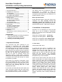
1
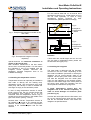
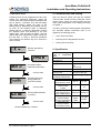
Heat Meter PolluStat E
Installation and Operating Instructions
Index
1. Important directions ..........................................1
2. Installation of components................................1
2.1 Flow meter ..................................................1
2.2 Installing the temperature sensors..............2
2.3 Installing the integrator................................2
3. Connection of temperature sensors .................3
4. Display options .................................................3
4.1 User menu (example) .................................4
4.2 Archive menu (example) .............................4
4.3 Service menu .............................................5
4.4 Parameter menu .........................................6
5. Functional test, lead-sealing.............................6
6. Specification .....................................................6
6.1 Battery-operated version.............................7
6.2 Mains-operated version ..............................7
7. Possible error situations ...................................7
8. Optional modules..............................................8
9. Appendix...........................................................8
9.1 Extension of sensor cable by means of a
junction box .......................................................8
Supplied items:
Heat meter PolluStat E (including temperature
sensors and bulb wells, if ordered)
Installation and operating instructions
Mounting and lead-sealing material
1. Important directions
This instrument has been delivered by the
producers in consistency with sound safety
engineering. In order to ensure a safe installation
and operation job read the complete instructions.
It is only allowed to open covers and remove
parts, where this can be done by hand. Otherwise
life parts might be exposed. And connectors can
be alive, too. All repair and maintenance jobs
have to be done by specially trained and
authorized experts. If body and/or connection
cables show any damages put the instrument out
of operation and ensure that nobody can restart
its operation by mistake.
Heat meters are measuring instruments, which
have to be handled with care. In order to protect
them against damage and dirt leave them in their
packing until you want to install them. Do not
clean them with anything else but a cloth
moistened with water.
If more than one heat meter are to be used in the
same accounting subject select the same meter
type and fitting position in order to achieve the
fairest possible accounting of heat consumption.
Battery-operated meters:
The battery must not be opened by force, be
short-circuited or exposed to water or
temperatures exceeding 80°C. Empty batteries
are special refuse and have to be disposed of at
suitable collection centers.
Mains-operated meters:
Protect the power pack by using a 6 A-fuse in the
installation site. Only specially trained and
authorized experts are allowed to do the
connecting job. Furthermore pay attention to the
standard technical rules - VDE 0100 in particular.
2. Installation of components
Pollustat E is not restricted to be used as heat
meter, but it can be installed in refrigeration
plants, too. Therefore the text hereinafter includes
following terms:
Return pipe of heating plants:
Supply pipe of heating plants:
Colder pipe
Warmer pipe
Return pipe of refrigeration plants: Warmer pipe
Supply pipe of refrigeration plants: Colder pipe
2.1 Flow meter
Valid standard: EN 1434-6
In general the flow sensor is installed in the
heating return pipe resp. the colder pipe. Use
Pollustat type EX if the flow meter is to be
installed in the heating supply pipe resp. the
warmer pipe An arrow on the flow meter body
shows the flow direction. The admissible
operating pressure and the admissible operating
temperature may not be exceeded.
Install shut-off valves before and after the flow
meter, so that there is no need to empty the pipe
system when the meter will be exchanged on
expiry of the verification period. A dirt trap suitably
located in the heating pipe system reduces
particle sediments in the heat meter. At first install
a fitting piece instead of the flow meter and flush
the pipe system thoroughly. Then close shut-off
valves, remove fitting piece, clean sealing
surfaces and install the flow meter using new
gaskets. Pay special attention not to reduce the
pipe cross section by bad positioning of the
gaskets, particularly when installing flanged-type
meters.
M H 4100 INT PolluStat E, page 1
Heat Meter PolluStat E
Installation and Operating Instructions
For the nominal sizes DN 15, 20 and 25 short
temperature sensors (e.g. overall length 45 mm)
can be used optionally. In case of using
temperature sensors produced by other
manufacturers, please proceed accordingly.
temperature
sensor
bulb well
measuring zone
Fig. 1: Example with integrator mounted on the
flow meter
approx. 10-15 mm
Fig. 3:
example for
nominal sizes
< DN 80
temperature sensor
Fig. 4:
bulb well
Example for
nominal sizes
> DN 100
approx. 10-15 mm
measuring zone
Fig.2: Example with integrator mounted
separately
Special direction for horizontal installation of
meters of Qp 15 and more:
Both ultrasonic transducers in the flow sensor
have to be in horizontal position. For this reason
the PolluStat E has to be installed with the
integrator turned upwards. Removed and
separately mounted integrators have to be
installed accordingly.
2.2 Installing the temperature sensors
Temperature sensors can optionally be installed in
bulb wells or directly into the heating resp.
refrigeration liquid. We recommend using bulb
wells (resp. ball valves) in order to facilitate the
exchange on expiry of the verification period.
In case of using temperature sensors of overall
length 100 mm and 150 mm, please ensure that
the measuring zone (approx. 10 to 15 mm
measured from the temperature sensor’s tip) is
positioned as near as possible in the middle of the
pipe cross section (see fig. 3 and 4).
Nominal sizes < DN 80: Temperature sensors to
be installed in an angle of 45° towards the flow
direction. Nominal sizes > DN 100: Temperature
sensors to be installed square with the flow
direction.
M H 4100 INT PolluStat E, page 2
Attention:
If bulb wells with overall length 100 mm and 150
mm are used in refrigeration plants, please use
the stainless steel type (V4A).
2.3 Installing the integrator
The heat meter is delivered with the integrator
mounted on the flow meter. Depending on the
flow meter’s installation (horizontal or vertical) the
integrator can be turned through steps of 90
degrees. Lift the spring catch with a screw driver
and take the integrator from the carrier plate.
Then turn the integrator to the required position,
adjust it to the bottom edge of the carrier plate, lift
the spring catch, attach the integrator onto the
carrier plate and release the spring catch.
If liquid temperatures exceed 90°C the
integrator has to be mounted separately, in
order to avoid damages of electronic parts
(see also fig. 2):
Unscrew the carrier plate from the flow meter, and
fix it at the required place using the two screws
and the two enclosed dowels. Then attach the
integrator as specified above.
Heat Meter PolluStat E
Installation and Operating Instructions
3. Connection of temperature sensors
4. Display options
To open the body push locking bolt to the right
and lift cover up
Our PolluStat E offers 4 different display menus:
PolluStat E can be operated with temperature
sensors type Pt 100 or Pt 500. The type to be
used is specified on the front side of the heat
meter body. Temperature sensors can be
connected directly (with 2 wires) or with 4 wires (in
order to extend temperature sensor cables by
max. 23 m, cable type: I-Y(St)Y 2x2x0.8)
Coordination as follows:
Supply pipe temperature sensor (warmer
pipe):
Connection type
Direct connection
(two wires)
Four wires
Terminals
5, 6
(see fig. 5)
5, 6 and 1, 2
(see fig. 6)
Return pipe temperature sensor (colder pipe):
Connection type
Direct connection
(two wires)
Four wires
Terminals
7, 8
(see fig. 5)
7, 8 and 3, 4
(see fig. 6)
Fig. 5:
direct
connection of
temperature
sensor
(with two
wires)
User menu
Archive menu
Service menu
Parameter menu
In normal condition the display switches on in
intervals of 4 seconds and shows the
accumulated heat consumption for a second.
Depress the red key for 2 seconds and then
release it in order to activate the first display item
of the user menu (accumulated heat value). In
order to have the other three menus displayed
proceed as follows:
Archive menu: Double click on key within 0.5
seconds.
Service menu: Switch to the item „segment
test” in the user menu, then depress key and
hold it for approx. 3 seconds.
Parameter
menu:
Switch
to
item
„accumulated volume” in the user menu, then
depress key and hold it for approx. 5 seconds.
If there is no key operation within five minutes, the
display returns automatically to the normal
condition. The display items marked with an
asterisk (*) can be masked out with the service
software „MiniCom” using the optical interface. A
short flashing of the asterisk symbol in the left
bottom display corner shows the reception of
every volume pulse received.
Fig. 6:
connection of
temperature
sensor cables
with 4 wires
Connect available cable screenings to the
terminals marked "┴"or below the clamp strap in
order to relief traction from the temperature
sensor cables.
Fig. 7: Change of display menus
M H 4100 INT PolluStat E, page 3
Heat Meter PolluStat E
Installation and Operating Instructions
4.1 User menu (example)
4.2 Archive menu (example)
Change from one display item to the next by
depressing the key once.
Starting with the current date the values at the
turns of the past 16 months are displayed.
Depress and hold the key, and the months are
displayed one after the other for one second each.
Release the key when the display arrives at the
required month:
Accumulated heat
consumption
Selected turn of
the month
Accumulated volume
Tariff function
(if activated)
Display loop showing the monthly
values (continued by short keystroke)
Heat
consumption at
selected turn
Segment test
Volume
at selected turn
Instantaneous flow *
Maximum
flow in the past
month *
Instantaneous
energy *
Maximum
energy in the
past month *
Instantaneous
temperature in warmer
pipe *
Instantaneous
temperature in colder
pipe *
Depress and hold the key for approx. 2
seconds in order to leave the display loop and
to select another month.
Instantaneous
temperature difference *
Next turn of the
month
Number specified by
customer
Etc..
To leave the archive menu double click on the key
or wait 5 minutes.
M H 4100 INT PolluStat E, page 4
Heat Meter PolluStat E
Installation and Operating Instructions
4.3 Service menu (example)
Date
Maximum flow *
Next item after 2 seconds
Maximum energy *
Date
Next item after 2 seconds
Maximum temperature
in warmer pipe *
Date
Next item after 2 seconds
Maximum temperature
in colder pipe *
Date
Next item after 2 seconds
Adjusted averaging time
for energy maximum *
Energy of the current
averaging period *
Primary M-Bus
address
Current
date *
Operating
days *
Secondary M-Bus
adresse (ID-Number)
Failure hours*
Version of
firmware
High-resolution
heat consumption*
(from qp10 please
multiply by
factor10)
High-resolution
Hocha
volume
* ufgelöste
Wärmemenge
(from qp 10 please*
multiply by
factor10)
To leave the service menu depress and hold the key for approx. 3 seconds or wait 5 minutes.
M H 4100 INT PolluStat E, page 5
Heat Meter PolluStat E
Installation and Operating Instructions
4.4 Parameter menu
5. Functional test, lead-sealing
Following items can be programmed in this menu
without any peripheral equipment. Select the
current value of the required item and depress the
key for approx. 2 seconds. Then the left display
digit starts blinking. Adjust the value of the
blinking digit by depressing and holding the key.
As soon as the required value is displayed,
release the key. A short key depression confirms
the adjusted value and switches to the next
display digit. Then proceed as before. The last
digit having been adjusted the display changes to
the next item. In order to leave the parameter
menu depress and hold the key for 5 seconds or
wait 5 minutes.
Open the shut-off valves and test the installed
units for leaks. Finally check by calling the current
values of flow, energy, as well as supply pipe and
return pipe temperature to the display according
to chapter 4.
In order to protect the meter against manipulation
the enclosed selflock lead-seals have to be
applied to the following points:
Union of the flow meter
Insertion point of temperature sensors
Locking bolt of the body
Number specified by
customer *
Current value
Secondary M-Bus
addresse (ID-Number) *
Current value
Averaging period for
energy maximum *
(3 to 765 minutes)
Current value
Primary M-Bus address
(1 to 250) *
Current value
Number specified by customer
M H 4100 INT PolluStat E, page 6
6. Specification
Temperature range of
heat or refrigeration
liquid
Admissible
ambient
temperature
Storage temperature
Integrator dimensions
5 ... 130 °C
5 ... 55 °C
- 10 °C ... + 60 °C
Approx. 170x 140 x 53
mm
(W x H x D)
Protection class
IP 54 acc.to DIN 40050
Dirt intensity according None or dry, nonto EN 61010
conductive dirt only
Overload cat. II
2.500 V surge voltage
according to EN 61010
Nominal flow of
0,6 - 6
10 - 60
flow sensor in m³/h
Pulse value
of flow sensor
1
10
in litres
Display of integrator
with decimal point 00000,000 000000,00
of m³, MWh and GJ
Pulse value for
0,001
0,01 MWh
remote readout
MWh
10 kWh
of heat consumption 1 kWh
Pulse value for
remote readout
1
10
of volume in litres
Heat Meter PolluStat E
Installation and Operating Instructions
6.1 Battery-operated version
Type:
3.6 Volt lithium battery
Durability:
Verification period
Such error messages can also appear on the
display of new heat meters, when – due to logistic
reasons – the flow sensor has not been filled with
water. This is no reason for a complaint because
such an error message will vanish after correct
installation of the meter.
6.2 Mains-operated version
Voltage:
220 ... 240 V AC
Frequency:
50/60 Hz
Max. consumption:
0,5 VA
Cable length:
approx. 1.1 m
Protect the power pack by using a 6 A fuse in
the installation site. Only specially trained and
authorized experts are allowed to do the
connecting job. Furthermore pay attention to
the standard technical rules – and VDE 0100 in
particular.
If nominal flow is exceeded by more than 140%,
following error message is displayed:
Err XXX4
After reducing the flow, this message will
disappear.
Codes (extract)
Decoding
Err 1010
Temperature sensors
changed by mistake resp.
temperature in colder pipe
exceeds temperature in
warmer pipe
One or both temperature
sensors is/are short-circuited
Cable failure of return pipe
temperature sensor resp.
sensor is not connected
Supply pipe temperature
sensor is short-circuited and
cable failure of return pipe
temperature sensor
Cable failure of supply pipe
temperature sensor resp.
sensor is not connected
Return pipe temperature
sensor is short-circuited and
cable failure of supply pipe
temperature sensor
Cable failure of supply pipe
and return pipe temperature
sensor resp. sensors are not
connected
Air in flow meter
Err 2010 or 3010
Err 4010 or 5010
7. Possible error situations
PolluStat E is equipped with an automatic selfchecking function. As soon as an error is
detected, the display shows a four-digit error code
„Err XYZW“, which can be decoded as follows:
Err 6010 or 7010
Err 8010 or 9010
Err A010 or B010
X:
Checking the temperature sensors
Y:
Checking the integrator
Z:
Error statistics
W:
Checking the ultrasonic measuring circuit
Err C010 or D010
Err 0006
Following error messages can appear, if – due to
insufficient venting of the pipe – there is air in the
flow sensor disturbing the ultrasonic signals.
Err 00 x 2
Err 00 x 6
Error situation „Err 1010“ is usually caused by
temporary system conditions when temperature in
the warmer pipe drops by 3 K or more below the
temperature in the colder pipe.
In case of all other errors situations please inform
our service department.
where „x“ stands for a figure from 1 to 9 or for a
capital from A to F.
M H 4100 INT PolluStat E, page 7
Heat Meter PolluStat E
Installation and Operating Instructions
8. Optional modules
PolluStat E can be supplemented with following
optional modules:
Remote readout plug-in circuit board
transmitting heat consumption and volume
pulses (for mains-operated version only)
Closing time:
Max. voltage:
Max. current:
approx. 125 ms
28 V DC or AC
0.1 A
Remote readout plug-in circuit board
transmitting heat consumption pulses (for
battery-operated version only)
Closing time:
Max. voltage:
Max. current:
approx. 125 ms
28 V DC or AC
0.1 A
M-Bus plug-in circuit board
Variable data logging according to EN 1434-3
Automatic Baud rate recognition (300 or 2400)
9. Appendix
Fig. 8: connection terminals of junction box
The two additional wires per sensor at the
terminal box in the integrator – i.e. 1 and 2 for the
higher temperature and 3 and 4 for the lower
temperature – are pure measuring cables. They
measure the voltage drop of sensor cable plus
platinum resistance at the point, where
measurement would have been accomplished in
case of normal connection without extension of
the cable.
Therefore the electric resistance of the extension
has no affects on the measurement.
9.1 Extension of sensor cable by means of a
junction box
Measuring sensors of our heat meters are
available with platinum thermometers in two
resistance versions: 100 Ohm (Pt 100) and 500
Ohm (Pt 500). The measuring sensors are
delivered with a connected screened two-wire
cable. Each heat meter integrator needs two
sensors. For this reason the sensors are paired
according to their resistance value and calibrated
before delivery. So it is prevented that different
cable resistances will falsify a temperature
difference measured in the heating plant.
In the site it is often required to extend the cable
length of one or both temperature sensors. The
length of the sensor cables of PolluStat E can be
extended by max. 23 m. In order to compensate
for the additional cable resistance, four-wire
cables are to be used. Use a screened four-wire
cable for the extension of each sensor cable (e.g.
I-Y(St)Y 2x2x0.8). It is most suitable to use our
junction box (order number 88599001) for the
extension (see fig.8). Each extension, even a
symmetrical one, requires a four-wire extension
cable.
.
M H 4100 INT PolluStat E, page 8
Material number: 28504135
Edition: May 2004
Subject to changes
Sensus Metering Systems GmbH
Industriestraße 16
D-67063 Ludwigshafen
Phone: + 49 (0) 621 6904-0
Fax: + 49 (0) 621 6904-1409
E-Mail: [email protected]