1
UM1718
User manual
STM32CubeMX for STM32 configuration
and initialization C code generation
Introduction
STM32CubeMX is a graphical tool for 32-bit ARM® Cortex® STM32 microcontrollers. It is
part of STMCube™ initiative (see Section 1) and is available either as a standalone
application or as an Eclipse plug-in for integration in Integrated Development Environments
(IDEs).
STM32CubeMX has the following key features:
•
Easy microcontroller selection covering whole STM32 portfolio.
•
Board selection from a list of STMicroelectronics boards.
•
Easy microcontroller configuration (pins, clock tree, peripherals, middleware) and
generation of the corresponding initialization C code.
•
Generation of configuration reports.
•
Generation of IDE ready projects for a selection of integrated development
environment tool chains.
STM32CubeMX projects include the generated initialization C code, STM32 HAL
drivers, the middleware stacks required for the user configuration, and all the relevant
files needed to open and build the project in the selected IDE.
•
Power consumption calculation for a user-defined application sequence.
•
Self-updates allowing the user to keep the STM32CubeMX up-to-date.
•
Downloading and updating STM32Cube™ firmware packages allowing the
download from www.st.com of the MCU firmware package required for the
development of the user application (see Appendix E: STM32Cube embedded
software packages for details on the STM32Cube package).
Although STM32CubeMX offers a user interface and generates a C code compliant with
STM32 MCU design and firmware solutions, it is recommended to refer to the product
technical documentation for details on actual implementation of microcontroller peripherals
and firmware.
Reference documents
The following documents are available from http//:www.st.com:
June 2014
•
STM32 microcontroller reference manuals
•
STM32 microcontroller datasheets
•
STM32Cube HAL driver user manuals for STM32F4xx (UM1725), STM32F2xx
(UM1742), STM32L0xx (UM1749), STM32F0xx (UM1785) and STM32F3xx (UM1786).
.
DocID025776 Rev 4
1/140
www.st.com
Contents
UM1718
Contents
1
STM32Cube overview . . . . . . . . . . . . . . . . . . . . . . . . . . . . . . . . . . . . . . . 11
2
Getting started with STM32CubeMX . . . . . . . . . . . . . . . . . . . . . . . . . . . 12
3
2.1
Principles . . . . . . . . . . . . . . . . . . . . . . . . . . . . . . . . . . . . . . . . . . . . . . . . . 12
2.2
Key features . . . . . . . . . . . . . . . . . . . . . . . . . . . . . . . . . . . . . . . . . . . . . . . 14
2.3
Rules and limitations . . . . . . . . . . . . . . . . . . . . . . . . . . . . . . . . . . . . . . . . 15
Installing and running STM32CubeMX . . . . . . . . . . . . . . . . . . . . . . . . . 16
3.1
3.2
3.3
3.4
3.5
4
System requirements . . . . . . . . . . . . . . . . . . . . . . . . . . . . . . . . . . . . . . . . 16
3.1.1
Supported operating systems and architectures . . . . . . . . . . . . . . . . . . 16
3.1.2
Memory prerequisites . . . . . . . . . . . . . . . . . . . . . . . . . . . . . . . . . . . . . . 16
3.1.3
Software requirements . . . . . . . . . . . . . . . . . . . . . . . . . . . . . . . . . . . . . . 16
Installing/uninstalling STM32CubeMX standalone version . . . . . . . . . . . 16
3.2.1
Installing STM32CubeMX standalone version . . . . . . . . . . . . . . . . . . . . 16
3.2.2
Uninstalling STM32CubeMX standalone version . . . . . . . . . . . . . . . . . . 17
Installing STM32CubeMX plug-in version . . . . . . . . . . . . . . . . . . . . . . . . 17
3.3.1
Downloading STM32CubeMX plug-in installation package . . . . . . . . . . 17
3.3.2
Installing STM32CubeMX as an Eclipse IDE plug-in . . . . . . . . . . . . . . . 17
3.3.3
Uninstalling STM32CubeMX as an Eclipse IDE plug-in . . . . . . . . . . . . . 19
Launching STM32CubeMX . . . . . . . . . . . . . . . . . . . . . . . . . . . . . . . . . . . 20
3.4.1
Running STM32CubeMX as standalone application . . . . . . . . . . . . . . . 20
3.4.2
Running STM32CubeMX plug-in from Eclipse IDE . . . . . . . . . . . . . . . . 20
Getting STM32Cube updates . . . . . . . . . . . . . . . . . . . . . . . . . . . . . . . . . . 21
3.5.1
Updater configuration . . . . . . . . . . . . . . . . . . . . . . . . . . . . . . . . . . . . . . 23
3.5.2
Downloading new libraries . . . . . . . . . . . . . . . . . . . . . . . . . . . . . . . . . . . 26
3.5.3
Checking for updates . . . . . . . . . . . . . . . . . . . . . . . . . . . . . . . . . . . . . . . 27
STM32CubeMX User Interface . . . . . . . . . . . . . . . . . . . . . . . . . . . . . . . . 28
4.1
Welcome page . . . . . . . . . . . . . . . . . . . . . . . . . . . . . . . . . . . . . . . . . . . . . 28
4.2
New project window . . . . . . . . . . . . . . . . . . . . . . . . . . . . . . . . . . . . . . . . . 29
4.3
Main window . . . . . . . . . . . . . . . . . . . . . . . . . . . . . . . . . . . . . . . . . . . . . . . 31
4.4
Toolbar and menus . . . . . . . . . . . . . . . . . . . . . . . . . . . . . . . . . . . . . . . . . . 33
4.4.1
2/140
File menu . . . . . . . . . . . . . . . . . . . . . . . . . . . . . . . . . . . . . . . . . . . . . . . . 34
DocID025776 Rev 4
UM1718
Contents
4.4.2
Project menu . . . . . . . . . . . . . . . . . . . . . . . . . . . . . . . . . . . . . . . . . . . . . 34
4.4.3
Pinout menu . . . . . . . . . . . . . . . . . . . . . . . . . . . . . . . . . . . . . . . . . . . . . . 35
4.4.4
Window menu . . . . . . . . . . . . . . . . . . . . . . . . . . . . . . . . . . . . . . . . . . . . 36
4.4.5
Help menu . . . . . . . . . . . . . . . . . . . . . . . . . . . . . . . . . . . . . . . . . . . . . . . 37
4.5
MCUs selection window . . . . . . . . . . . . . . . . . . . . . . . . . . . . . . . . . . . . . . 37
4.6
Set unused / Reset used GPIOs windows . . . . . . . . . . . . . . . . . . . . . . . . 38
4.7
Project Settings Window . . . . . . . . . . . . . . . . . . . . . . . . . . . . . . . . . . . . . 41
4.8
Update Manager Windows . . . . . . . . . . . . . . . . . . . . . . . . . . . . . . . . . . . . 43
4.9
About Window . . . . . . . . . . . . . . . . . . . . . . . . . . . . . . . . . . . . . . . . . . . . . 43
4.10
Pinout view . . . . . . . . . . . . . . . . . . . . . . . . . . . . . . . . . . . . . . . . . . . . . . . . 43
4.11
4.12
4.13
4.10.1
IP tree pane . . . . . . . . . . . . . . . . . . . . . . . . . . . . . . . . . . . . . . . . . . . . . . 45
4.10.2
Chip view . . . . . . . . . . . . . . . . . . . . . . . . . . . . . . . . . . . . . . . . . . . . . . . . 46
4.10.3
Chip view advanced actions . . . . . . . . . . . . . . . . . . . . . . . . . . . . . . . . . 49
4.10.4
Keep Current Signals Placement . . . . . . . . . . . . . . . . . . . . . . . . . . . . . . 51
4.10.5
Pinning and labeling signals on pins . . . . . . . . . . . . . . . . . . . . . . . . . . . 52
Configuration view . . . . . . . . . . . . . . . . . . . . . . . . . . . . . . . . . . . . . . . . . . 53
4.11.1
IP and Middleware Configuration window (for STM32F0, STM32F2,
STM32F3, STM32F4 and STM32L0 series only) . . . . . . . . . . . . . . . . . 55
4.11.2
GPIO Configuration window . . . . . . . . . . . . . . . . . . . . . . . . . . . . . . . . . 57
4.11.3
DMA Configuration window . . . . . . . . . . . . . . . . . . . . . . . . . . . . . . . . . . 58
4.11.4
NVIC Configuration window . . . . . . . . . . . . . . . . . . . . . . . . . . . . . . . . . . 60
Clock tree configuration view (for STM32F0, STM32F2,
STM32F3, STM32F4, and STM32L0 series only) . . . . . . . . . . . . . . . . . . 62
4.12.1
Clock tree configuration functions . . . . . . . . . . . . . . . . . . . . . . . . . . . . . 62
4.12.2
Recommendations . . . . . . . . . . . . . . . . . . . . . . . . . . . . . . . . . . . . . . . . . 64
4.12.3
STM32F43x/42x power-over drive feature . . . . . . . . . . . . . . . . . . . . . . 64
4.12.4
Clock tree glossary . . . . . . . . . . . . . . . . . . . . . . . . . . . . . . . . . . . . . . . . 66
Power Consumption Calculator (PCC) view . . . . . . . . . . . . . . . . . . . . . . . 66
4.13.1
Building a power consumption sequence . . . . . . . . . . . . . . . . . . . . . . . 67
4.13.2
User-defined power sequence and results . . . . . . . . . . . . . . . . . . . . . . 70
4.13.3
Power sequence step parameters glossary . . . . . . . . . . . . . . . . . . . . . . 75
4.13.4
Battery glossary . . . . . . . . . . . . . . . . . . . . . . . . . . . . . . . . . . . . . . . . . . . 77
5
STM32CubeMX C Code generation overview . . . . . . . . . . . . . . . . . . . . 78
6
Tutorial 1: From pinout to project C code generation
using an STM32F4 MCU . . . . . . . . . . . . . . . . . . . . . . . . . . . . . . . . . . . . . 79
DocID025776 Rev 4
3/140
6
Contents
UM1718
6.1
Creating a new STM32CubeMX Project . . . . . . . . . . . . . . . . . . . . . . . . . 79
6.2
Configuring the MCU pinout . . . . . . . . . . . . . . . . . . . . . . . . . . . . . . . . . . . 82
6.3
Saving the project . . . . . . . . . . . . . . . . . . . . . . . . . . . . . . . . . . . . . . . . . . . 83
6.4
Generating the report . . . . . . . . . . . . . . . . . . . . . . . . . . . . . . . . . . . . . . . . 84
6.5
Configuring the MCU Clock tree . . . . . . . . . . . . . . . . . . . . . . . . . . . . . . . . 84
6.6
Configuring the MCU initialization parameters . . . . . . . . . . . . . . . . . . . . . 87
6.7
6.8
6.6.1
Initial conditions . . . . . . . . . . . . . . . . . . . . . . . . . . . . . . . . . . . . . . . . . . . 87
6.6.2
Configuring the peripherals . . . . . . . . . . . . . . . . . . . . . . . . . . . . . . . . . . 88
6.6.3
Configuring the GPIOs . . . . . . . . . . . . . . . . . . . . . . . . . . . . . . . . . . . . . . 89
6.6.4
Configuring the DMAs . . . . . . . . . . . . . . . . . . . . . . . . . . . . . . . . . . . . . . 90
6.6.5
Configuring the middleware . . . . . . . . . . . . . . . . . . . . . . . . . . . . . . . . . 91
Generating a complete C project . . . . . . . . . . . . . . . . . . . . . . . . . . . . . . . 94
6.7.1
Setting project options . . . . . . . . . . . . . . . . . . . . . . . . . . . . . . . . . . . . . . 94
6.7.2
Downloading firmware package and generating the C code . . . . . . . . . 95
Building and updating the C code project . . . . . . . . . . . . . . . . . . . . . . . . . 99
7
Tutorial 2 - Generating GPIO initialization C code
(STM32F1/L1 series only) . . . . . . . . . . . . . . . . . . . . . . . . . . . . . . . . . . . 103
8
Tutorial 3 - Getting power consumption results
for a user-defined sequence . . . . . . . . . . . . . . . . . . . . . . . . . . . . . . . . 106
8.1
9
4/140
Creating a new power sequence . . . . . . . . . . . . . . . . . . . . . . . . . . . . . . 106
8.1.1
Adding a step . . . . . . . . . . . . . . . . . . . . . . . . . . . . . . . . . . . . . . . . . . . . 107
8.1.2
Moving a step . . . . . . . . . . . . . . . . . . . . . . . . . . . . . . . . . . . . . . . . . . . 107
8.1.3
Deleting a step . . . . . . . . . . . . . . . . . . . . . . . . . . . . . . . . . . . . . . . . . . . 107
8.2
Configuring a step in the power sequence . . . . . . . . . . . . . . . . . . . . . . . 108
8.3
Reviewing results . . . . . . . . . . . . . . . . . . . . . . . . . . . . . . . . . . . . . . . . . . 108
FAQ . . . . . . . . . . . . . . . . . . . . . . . . . . . . . . . . . . . . . . . . . . . . . . . . . . . . . 111
9.1
On the Pinout configuration panel, why does STM32CubeMX
move some functions when I add a new peripheral mode? . . . . . . . . . . . 111
9.2
How can I manually force a function remapping? . . . . . . . . . . . . . . . . . . 111
9.3
Why are some pins highlighted in yellow or in light green in
the Chip view? Why cannot I change the function of some
pins (when I click some pins, nothing happens)? . . . . . . . . . . . . . . . . . . . 111
9.4
Why do I get the error “Java 7 update 45’ when installing
‘Java 7 update 45’ or a more recent version of the JRE? . . . . . . . . . . . . 111
DocID025776 Rev 4
UM1718
Contents
9.5
Why does the RTC multiplexer remain inactive on the Clock tree view? .112
9.6
How can I select LSE and HSE as clock source and
change the frequency? . . . . . . . . . . . . . . . . . . . . . . . . . . . . . . . . . . . . . . .113
9.7
Why STM32CubeMX does not allow me to configure PC13,
PC14, PC15 and PI8 as outputs when one of them
is already configured as an output? . . . . . . . . . . . . . . . . . . . . . . . . . . . . .113
Appendix A STM32CubeMX pin assignment rules . . . . . . . . . . . . . . . . . . . . . . 114
A.1
Block consistency . . . . . . . . . . . . . . . . . . . . . . . . . . . . . . . . . . . . . . . . . . .114
A.2
Block inter-dependency. . . . . . . . . . . . . . . . . . . . . . . . . . . . . . . . . . . . . . .117
A.3
One block = one peripheral mode . . . . . . . . . . . . . . . . . . . . . . . . . . . . . . 120
A.4
Block remapping (STM32F10x only) . . . . . . . . . . . . . . . . . . . . . . . . . . . . 120
A.5
Function remapping. . . . . . . . . . . . . . . . . . . . . . . . . . . . . . . . . . . . . . . . . 121
A.6
Block shifting (only for STM32F10x and when
“Keep Current Signals placement” is unchecked) . . . . . . . . . . . . . . . . . . 122
A.7
Setting and clearing a peripheral mode. . . . . . . . . . . . . . . . . . . . . . . . . . 123
A.8
Mapping a function individually . . . . . . . . . . . . . . . . . . . . . . . . . . . . . . . 123
A.9
GPIO signals mapping . . . . . . . . . . . . . . . . . . . . . . . . . . . . . . . . . . . . . . 123
Appendix B STM32CubeMX C code generation design
choices and limitations . . . . . . . . . . . . . . . . . . . . . . . . . . . . . . . . . . 124
B.1
STM32CubeMX generated C code and user sections . . . . . . . . . . . . . . 124
B.2
STM32CubeMX design choices for peripheral initialization . . . . . . . . . . 124
B.3
STM32CubeMX design choices and limitations for
middleware initialization . . . . . . . . . . . . . . . . . . . . . . . . . . . . . . . . . . . . . 125
B.3.1
Overview. . . . . . . . . . . . . . . . . . . . . . . . . . . . . . . . . . . . . . . . . . . . . . . . 125
B.3.2
USB Host . . . . . . . . . . . . . . . . . . . . . . . . . . . . . . . . . . . . . . . . . . . . . . . 125
B.3.3
USB Device . . . . . . . . . . . . . . . . . . . . . . . . . . . . . . . . . . . . . . . . . . . . . 125
B.3.4
FATFS . . . . . . . . . . . . . . . . . . . . . . . . . . . . . . . . . . . . . . . . . . . . . . . . . . 126
B.3.5
FreeRTOS. . . . . . . . . . . . . . . . . . . . . . . . . . . . . . . . . . . . . . . . . . . . . . . 126
B.3.6
LwIP . . . . . . . . . . . . . . . . . . . . . . . . . . . . . . . . . . . . . . . . . . . . . . . . . . . 127
Appendix C STM32 microcontrollers naming conventions . . . . . . . . . . . . . . . 129
Appendix D STM32 microcontrollers power consumption parameters . . . . . 131
D.1
Power modes . . . . . . . . . . . . . . . . . . . . . . . . . . . . . . . . . . . . . . . . . . . . . 131
D.1.1
STM32L1 series . . . . . . . . . . . . . . . . . . . . . . . . . . . . . . . . . . . . . . . . . . 131
DocID025776 Rev 4
5/140
6
Contents
UM1718
D.2
Appendix E
10
6/140
D.1.2
STM32F4 series . . . . . . . . . . . . . . . . . . . . . . . . . . . . . . . . . . . . . . . . . . 132
D.1.3
STM32L0 series . . . . . . . . . . . . . . . . . . . . . . . . . . . . . . . . . . . . . . . . . . 133
Power consumption ranges. . . . . . . . . . . . . . . . . . . . . . . . . . . . . . . . . . . 134
D.2.1
STM32L1 series feature 3 VCORE ranges. . . . . . . . . . . . . . . . . . . . . . 134
D.2.2
STM32F4 series feature several VCORE scales . . . . . . . . . . . . . . . . . 135
D.2.3
STM32L0 series feature 3 VCORE ranges. . . . . . . . . . . . . . . . . . . . . . 135
STM32Cube embedded software packages . . . . . . . . . . . . . . . . . 136
Revision history . . . . . . . . . . . . . . . . . . . . . . . . . . . . . . . . . . . . . . . . . . 137
DocID025776 Rev 4
UM1718
List of tables
List of tables
Table 1.
Table 2.
Table 3.
Table 4.
Table 5.
Table 6.
Table 7.
Table 8.
Table 9.
Table 10.
Table 11.
Table 12.
Table 13.
Table 14.
Table 15.
Welcome page shortcuts . . . . . . . . . . . . . . . . . . . . . . . . . . . . . . . . . . . . . . . . . . . . . . . . . . 29
File menu functions. . . . . . . . . . . . . . . . . . . . . . . . . . . . . . . . . . . . . . . . . . . . . . . . . . . . . . . 34
Project menu. . . . . . . . . . . . . . . . . . . . . . . . . . . . . . . . . . . . . . . . . . . . . . . . . . . . . . . . . . . . 34
Pinout menu . . . . . . . . . . . . . . . . . . . . . . . . . . . . . . . . . . . . . . . . . . . . . . . . . . . . . . . . . . . . 35
Window menu . . . . . . . . . . . . . . . . . . . . . . . . . . . . . . . . . . . . . . . . . . . . . . . . . . . . . . . . . . . 36
Help menu . . . . . . . . . . . . . . . . . . . . . . . . . . . . . . . . . . . . . . . . . . . . . . . . . . . . . . . . . . . . . 37
IP tree pane - icons and color scheme . . . . . . . . . . . . . . . . . . . . . . . . . . . . . . . . . . . . . . . . 45
STM32CubeMX Chip view - Icons and color scheme. . . . . . . . . . . . . . . . . . . . . . . . . . . . . 47
IP configuration buttons . . . . . . . . . . . . . . . . . . . . . . . . . . . . . . . . . . . . . . . . . . . . . . . . . . . 55
IP Configuration window buttons and tooltips . . . . . . . . . . . . . . . . . . . . . . . . . . . . . . . . . . . 56
Clock tree view widget . . . . . . . . . . . . . . . . . . . . . . . . . . . . . . . . . . . . . . . . . . . . . . . . . . . . 64
Voltage scaling versus power over-drive and HCLK frequency . . . . . . . . . . . . . . . . . . . . . 65
Relations between power over-drive and HCLK frequency . . . . . . . . . . . . . . . . . . . . . . . . 65
Glossary . . . . . . . . . . . . . . . . . . . . . . . . . . . . . . . . . . . . . . . . . . . . . . . . . . . . . . . . . . . . . . . 66
Document revision history . . . . . . . . . . . . . . . . . . . . . . . . . . . . . . . . . . . . . . . . . . . . . . . . 137
DocID025776 Rev 4
7/140
7
List of figures
UM1718
List of figures
Figure 1.
Figure 2.
Figure 3.
Figure 4.
Figure 5.
Figure 6.
Figure 7.
Figure 8.
Figure 9.
Figure 10.
Figure 11.
Figure 12.
Figure 13.
Figure 14.
Figure 15.
Figure 16.
Figure 17.
Figure 18.
Figure 19.
Figure 20.
Figure 21.
Figure 22.
Figure 23.
Figure 24.
Figure 25.
Figure 26.
Figure 27.
Figure 28.
Figure 29.
Figure 30.
Figure 31.
Figure 32.
Figure 33.
Figure 34.
Figure 35.
Figure 36.
Figure 37.
Figure 38.
Figure 39.
Figure 40.
Figure 41.
Figure 42.
Figure 43.
Figure 44.
Figure 45.
8/140
Overview of STM32CubeMX C code generation flow. . . . . . . . . . . . . . . . . . . . . . . . . . . . . 13
Adding STM32CubeMX plug-in archive . . . . . . . . . . . . . . . . . . . . . . . . . . . . . . . . . . . . . . . 18
Installing STM32CubeMX plug-in . . . . . . . . . . . . . . . . . . . . . . . . . . . . . . . . . . . . . . . . . . . . 18
Closing STM32CubeMX perspective . . . . . . . . . . . . . . . . . . . . . . . . . . . . . . . . . . . . . . . . . 19
Uninstalling STM32CubeMX plug-in . . . . . . . . . . . . . . . . . . . . . . . . . . . . . . . . . . . . . . . . . . 19
Opening Eclipse plug-in . . . . . . . . . . . . . . . . . . . . . . . . . . . . . . . . . . . . . . . . . . . . . . . . . . . 20
STM32CubeMX perspective . . . . . . . . . . . . . . . . . . . . . . . . . . . . . . . . . . . . . . . . . . . . . . . . 21
Displaying Windows default proxy settings. . . . . . . . . . . . . . . . . . . . . . . . . . . . . . . . . . . . . 22
Updater Settings tab . . . . . . . . . . . . . . . . . . . . . . . . . . . . . . . . . . . . . . . . . . . . . . . . . . . . . . 24
Connection Parameters tab - No proxy . . . . . . . . . . . . . . . . . . . . . . . . . . . . . . . . . . . . . . . 25
Connection Parameters tab - Use System proxy parameters. . . . . . . . . . . . . . . . . . . . . . . 25
Connection Parameters tab - Manual Configuration of Proxy Server . . . . . . . . . . . . . . . . . 26
New Libraires Manager window . . . . . . . . . . . . . . . . . . . . . . . . . . . . . . . . . . . . . . . . . . . . . 27
STM32CubeMX Welcome page . . . . . . . . . . . . . . . . . . . . . . . . . . . . . . . . . . . . . . . . . . . . . 28
New Project window . . . . . . . . . . . . . . . . . . . . . . . . . . . . . . . . . . . . . . . . . . . . . . . . . . . . . . 30
STM32CubeMX Main window upon MCU selection . . . . . . . . . . . . . . . . . . . . . . . . . . . . . . 31
STM32CubeMX Main window upon board selection
(Peripheral default option unchecked) . . . . . . . . . . . . . . . . . . . . . . . . . . . . . . . . . . . . . . . . 32
STM32CubeMX Main window upon board selection
(Peripheral default option checked) . . . . . . . . . . . . . . . . . . . . . . . . . . . . . . . . . . . . . . . . . . 33
Pinout menus (Pinout tab selected) . . . . . . . . . . . . . . . . . . . . . . . . . . . . . . . . . . . . . . . . . . 35
Pinout menus (Pinout tab not selected) . . . . . . . . . . . . . . . . . . . . . . . . . . . . . . . . . . . . . . . 35
MCU selection menu . . . . . . . . . . . . . . . . . . . . . . . . . . . . . . . . . . . . . . . . . . . . . . . . . . . . . 37
Set unused pins window . . . . . . . . . . . . . . . . . . . . . . . . . . . . . . . . . . . . . . . . . . . . . . . . . . . 38
Reset used pins window . . . . . . . . . . . . . . . . . . . . . . . . . . . . . . . . . . . . . . . . . . . . . . . . . . . 38
Set unused GPIO pins with Keep Current Signals Placement checked . . . . . . . . . . . . . . . 39
Set unused GPIO pins with Keep Current Signals Placement unchecked . . . . . . . . . . . . . 40
Project Settings window . . . . . . . . . . . . . . . . . . . . . . . . . . . . . . . . . . . . . . . . . . . . . . . . . . . 41
Project Settings Code Generator . . . . . . . . . . . . . . . . . . . . . . . . . . . . . . . . . . . . . . . . . . . . 42
About window . . . . . . . . . . . . . . . . . . . . . . . . . . . . . . . . . . . . . . . . . . . . . . . . . . . . . . . . . . . 43
STM32CubeMX Pinout view . . . . . . . . . . . . . . . . . . . . . . . . . . . . . . . . . . . . . . . . . . . . . . . . 44
Chip view . . . . . . . . . . . . . . . . . . . . . . . . . . . . . . . . . . . . . . . . . . . . . . . . . . . . . . . . . . . . . . 46
Red highlights and tooltip example: no mode configuration available . . . . . . . . . . . . . . . . 48
Orange highlight and tooltip example: some configurations unavailable . . . . . . . . . . . . . . 49
Tooltip example: all configurations unavailable . . . . . . . . . . . . . . . . . . . . . . . . . . . . . . . . . 49
Modifying pin assignments from the chip view . . . . . . . . . . . . . . . . . . . . . . . . . . . . . . . . . . 49
Example of remapping in case of block of pins consistency. . . . . . . . . . . . . . . . . . . . . . . . 50
Pins/Signals Options window. . . . . . . . . . . . . . . . . . . . . . . . . . . . . . . . . . . . . . . . . . . . . . . 53
STM32CubeMX Configuration view -STM32F0/F2/F3/F4/L0 series. . . . . . . . . . . . . . . . . . 54
STM32CubeMX Configuration view - STM32F1/L1 series . . . . . . . . . . . . . . . . . . . . . . . . . 54
Configuration window tabs for GPIO, DMA and NVIC settings
[STM32F4 series] . . . . . . . . . . . . . . . . . . . . . . . . . . . . . . . . . . . . . . . . . . . . . . . . . . . . . . . . 55
UART4 IP Configuration window [STM32F4 series] . . . . . . . . . . . . . . . . . . . . . . . . . . . . . . 56
GPIO Configuration window - GPIO selection . . . . . . . . . . . . . . . . . . . . . . . . . . . . . . . . . . 57
GPIO Configuration window - displaying GPIO settings . . . . . . . . . . . . . . . . . . . . . . . . . . . 57
GPIO configuration grouped by IP . . . . . . . . . . . . . . . . . . . . . . . . . . . . . . . . . . . . . . . . . . . 58
Multiple Pins Configuration . . . . . . . . . . . . . . . . . . . . . . . . . . . . . . . . . . . . . . . . . . . . . . . . . 58
Adding a new DMA request . . . . . . . . . . . . . . . . . . . . . . . . . . . . . . . . . . . . . . . . . . . . . . . . 59
DocID025776 Rev 4
UM1718
Figure 46.
Figure 47.
Figure 48.
Figure 49.
Figure 50.
Figure 51.
Figure 52.
Figure 53.
Figure 54.
Figure 55.
Figure 56.
Figure 57.
Figure 58.
Figure 59.
Figure 60.
Figure 61.
Figure 62.
Figure 63.
Figure 64.
Figure 65.
Figure 66.
Figure 67.
Figure 68.
Figure 69.
Figure 70.
Figure 71.
Figure 72.
Figure 73.
Figure 74.
Figure 75.
Figure 76.
Figure 77.
Figure 78.
Figure 79.
Figure 80.
Figure 81.
Figure 82.
Figure 83.
Figure 84.
Figure 85.
Figure 86.
Figure 87.
Figure 88.
Figure 89.
Figure 90.
Figure 91.
Figure 92.
Figure 93.
Figure 94.
Figure 95.
Figure 96.
Figure 97.
List of figures
DMA Configuration . . . . . . . . . . . . . . . . . . . . . . . . . . . . . . . . . . . . . . . . . . . . . . . . . . . . . . . 59
DMA MemToMem configuration . . . . . . . . . . . . . . . . . . . . . . . . . . . . . . . . . . . . . . . . . . . . . 60
NVIC Configuration window . . . . . . . . . . . . . . . . . . . . . . . . . . . . . . . . . . . . . . . . . . . . . . . . 61
STM32F429xx Clock Tree configuration view . . . . . . . . . . . . . . . . . . . . . . . . . . . . . . . . . . 63
Power consumption calculator default view . . . . . . . . . . . . . . . . . . . . . . . . . . . . . . . . . . . . 67
Battery selection . . . . . . . . . . . . . . . . . . . . . . . . . . . . . . . . . . . . . . . . . . . . . . . . . . . . . . . . . 68
Building a power consumption sequence . . . . . . . . . . . . . . . . . . . . . . . . . . . . . . . . . . . . . . 69
Power consumption sequence: new step default view (STM32F4 example) . . . . . . . . . . . 70
Power Consumption Calculator view after sequence building . . . . . . . . . . . . . . . . . . . . . . 71
Step management functions . . . . . . . . . . . . . . . . . . . . . . . . . . . . . . . . . . . . . . . . . . . . . . . . 71
Sequence table management functions . . . . . . . . . . . . . . . . . . . . . . . . . . . . . . . . . . . . . . . 71
STM32F4 PCC step edited in Edit Step window (STM32F4 example). . . . . . . . . . . . . . . . 72
Power consumption sequence: new step configured (STM32F4 example) . . . . . . . . . . . . 73
ADC selected in Pinout view. . . . . . . . . . . . . . . . . . . . . . . . . . . . . . . . . . . . . . . . . . . . . . . . 74
PCC Step configuration window: ADC enabled using import pinout. . . . . . . . . . . . . . . . . . 74
Description of the result section . . . . . . . . . . . . . . . . . . . . . . . . . . . . . . . . . . . . . . . . . . . . . 75
Peripheral power consumption tooltip. . . . . . . . . . . . . . . . . . . . . . . . . . . . . . . . . . . . . . . . . 77
MCU selection . . . . . . . . . . . . . . . . . . . . . . . . . . . . . . . . . . . . . . . . . . . . . . . . . . . . . . . . . . 79
Pinout view with MCUs selection . . . . . . . . . . . . . . . . . . . . . . . . . . . . . . . . . . . . . . . . . . . . 80
Pinout view without MCUs selection window . . . . . . . . . . . . . . . . . . . . . . . . . . . . . . . . . . . 81
GPIO pin configuration . . . . . . . . . . . . . . . . . . . . . . . . . . . . . . . . . . . . . . . . . . . . . . . . . . . . 82
Timer configuration . . . . . . . . . . . . . . . . . . . . . . . . . . . . . . . . . . . . . . . . . . . . . . . . . . . . . . . 82
Simple pinout configuration . . . . . . . . . . . . . . . . . . . . . . . . . . . . . . . . . . . . . . . . . . . . . . . . 83
Save Project As window . . . . . . . . . . . . . . . . . . . . . . . . . . . . . . . . . . . . . . . . . . . . . . . . . . . 83
Generate Project Report - New project creation . . . . . . . . . . . . . . . . . . . . . . . . . . . . . . . . . 84
Generate Project Report - Project successfully created . . . . . . . . . . . . . . . . . . . . . . . . . . . 84
Clock tree view . . . . . . . . . . . . . . . . . . . . . . . . . . . . . . . . . . . . . . . . . . . . . . . . . . . . . . . . . . 85
HSE clock source disabled . . . . . . . . . . . . . . . . . . . . . . . . . . . . . . . . . . . . . . . . . . . . . . . . . 85
HSI clock enabled . . . . . . . . . . . . . . . . . . . . . . . . . . . . . . . . . . . . . . . . . . . . . . . . . . . . . . . . 85
HSE clock source enabled . . . . . . . . . . . . . . . . . . . . . . . . . . . . . . . . . . . . . . . . . . . . . . . . . 86
External PLL clock source enabled . . . . . . . . . . . . . . . . . . . . . . . . . . . . . . . . . . . . . . . . . . 86
Configuration view . . . . . . . . . . . . . . . . . . . . . . . . . . . . . . . . . . . . . . . . . . . . . . . . . . . . . . . 87
Case of IP without configuration parameters . . . . . . . . . . . . . . . . . . . . . . . . . . . . . . . . . . . 88
Timer 3 configuration window . . . . . . . . . . . . . . . . . . . . . . . . . . . . . . . . . . . . . . . . . . . . . . . 88
Timer 3 configuration . . . . . . . . . . . . . . . . . . . . . . . . . . . . . . . . . . . . . . . . . . . . . . . . . . . . . 89
GPIO configuration color scheme and tooltip . . . . . . . . . . . . . . . . . . . . . . . . . . . . . . . . . . . 89
GPIO mode configuration . . . . . . . . . . . . . . . . . . . . . . . . . . . . . . . . . . . . . . . . . . . . . . . . . . 90
DMA Parameters configuration window . . . . . . . . . . . . . . . . . . . . . . . . . . . . . . . . . . . . . . . 91
FATFS disabled . . . . . . . . . . . . . . . . . . . . . . . . . . . . . . . . . . . . . . . . . . . . . . . . . . . . . . . . . 91
USB Host . . . . . . . . . . . . . . . . . . . . . . . . . . . . . . . . . . . . . . . . . . . . . . . . . . . . . . . . . . . . . . 91
FATFS over USB mode enabled . . . . . . . . . . . . . . . . . . . . . . . . . . . . . . . . . . . . . . . . . . . . 92
Configuration view with FATFS and USB enabled . . . . . . . . . . . . . . . . . . . . . . . . . . . . . . . 92
FATFS IP instances . . . . . . . . . . . . . . . . . . . . . . . . . . . . . . . . . . . . . . . . . . . . . . . . . . . . . . 93
FATFS define statements . . . . . . . . . . . . . . . . . . . . . . . . . . . . . . . . . . . . . . . . . . . . . . . . . . 93
Project Settings and toolchain choice . . . . . . . . . . . . . . . . . . . . . . . . . . . . . . . . . . . . . . . . . 94
Code Generator tab in Project Settings . . . . . . . . . . . . . . . . . . . . . . . . . . . . . . . . . . . . . . . 95
Missing firmware package warning message . . . . . . . . . . . . . . . . . . . . . . . . . . . . . . . . . . . 95
Error during download . . . . . . . . . . . . . . . . . . . . . . . . . . . . . . . . . . . . . . . . . . . . . . . . . . . . 96
Updater settings for download . . . . . . . . . . . . . . . . . . . . . . . . . . . . . . . . . . . . . . . . . . . . . . 96
Updater settings with connection . . . . . . . . . . . . . . . . . . . . . . . . . . . . . . . . . . . . . . . . . . . . 96
Downloading the firmware package . . . . . . . . . . . . . . . . . . . . . . . . . . . . . . . . . . . . . . . . . . 97
Unzipping the firmware package . . . . . . . . . . . . . . . . . . . . . . . . . . . . . . . . . . . . . . . . . . . . 97
DocID025776 Rev 4
9/140
10
List of figures
Figure 98.
Figure 99.
Figure 100.
Figure 101.
Figure 102.
Figure 103.
Figure 104.
Figure 105.
Figure 106.
Figure 107.
Figure 108.
Figure 109.
Figure 110.
Figure 111.
Figure 112.
Figure 113.
Figure 114.
Figure 115.
Figure 116.
Figure 117.
Figure 118.
Figure 119.
Figure 120.
Figure 121.
Figure 122.
Figure 123.
Figure 124.
Figure 125.
Figure 126.
Figure 127.
Figure 128.
Figure 129.
Figure 130.
Figure 131.
Figure 132.
Figure 133.
Figure 134.
Figure 135.
Figure 136.
10/140
UM1718
C code generation complete . . . . . . . . . . . . . . . . . . . . . . . . . . . . . . . . . . . . . . . . . . . . . . . . 97
C code generation output folder . . . . . . . . . . . . . . . . . . . . . . . . . . . . . . . . . . . . . . . . . . . . . 98
C code generation output: Projects folder . . . . . . . . . . . . . . . . . . . . . . . . . . . . . . . . . . . . . 99
C code generation for EWARM . . . . . . . . . . . . . . . . . . . . . . . . . . . . . . . . . . . . . . . . . . . . . 99
STM32CubeMX generated project open in IAR IDE . . . . . . . . . . . . . . . . . . . . . . . . . . . . 100
IAR options . . . . . . . . . . . . . . . . . . . . . . . . . . . . . . . . . . . . . . . . . . . . . . . . . . . . . . . . . . . . 100
SWD connection . . . . . . . . . . . . . . . . . . . . . . . . . . . . . . . . . . . . . . . . . . . . . . . . . . . . . . . . 101
Project building log . . . . . . . . . . . . . . . . . . . . . . . . . . . . . . . . . . . . . . . . . . . . . . . . . . . . . . 101
User Section 3 . . . . . . . . . . . . . . . . . . . . . . . . . . . . . . . . . . . . . . . . . . . . . . . . . . . . . . . . . 102
User Section 4 . . . . . . . . . . . . . . . . . . . . . . . . . . . . . . . . . . . . . . . . . . . . . . . . . . . . . . . . . 102
Configuration view . . . . . . . . . . . . . . . . . . . . . . . . . . . . . . . . . . . . . . . . . . . . . . . . . . . . . . 103
STM32L1 Configuration view . . . . . . . . . . . . . . . . . . . . . . . . . . . . . . . . . . . . . . . . . . . . . . 103
Choosing a C code generation folder . . . . . . . . . . . . . . . . . . . . . . . . . . . . . . . . . . . . . . . . 104
C code generation confirmation message . . . . . . . . . . . . . . . . . . . . . . . . . . . . . . . . . . . . 104
GPIO initialization output folders . . . . . . . . . . . . . . . . . . . . . . . . . . . . . . . . . . . . . . . . . . . 104
GPIO initialization main function . . . . . . . . . . . . . . . . . . . . . . . . . . . . . . . . . . . . . . . . . . . . 105
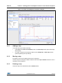
Power Consumption Calculation example . . . . . . . . . . . . . . . . . . . . . . . . . . . . . . . . . . . . 107
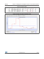
Sequence table . . . . . . . . . . . . . . . . . . . . . . . . . . . . . . . . . . . . . . . . . . . . . . . . . . . . . . . . . 109
Power Consumption Calculation results . . . . . . . . . . . . . . . . . . . . . . . . . . . . . . . . . . . . . . 109
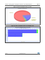
Power consumption results - pie chart . . . . . . . . . . . . . . . . . . . . . . . . . . . . . . . . . . . . . . . 110
Power consumption results - IP consumption chart . . . . . . . . . . . . . . . . . . . . . . . . . . . . . 110
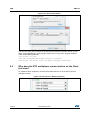
Java Control Panel . . . . . . . . . . . . . . . . . . . . . . . . . . . . . . . . . . . . . . . . . . . . . . . . . . . . . . 112
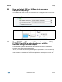
Pinout view - Enabling the RTC . . . . . . . . . . . . . . . . . . . . . . . . . . . . . . . . . . . . . . . . . . . . 112
Pinout view - Enabling LSE and HSE clocks . . . . . . . . . . . . . . . . . . . . . . . . . . . . . . . . . . 113
Pinout view - Setting LSE/HSE clock frequency . . . . . . . . . . . . . . . . . . . . . . . . . . . . . . . . 113
Block mapping . . . . . . . . . . . . . . . . . . . . . . . . . . . . . . . . . . . . . . . . . . . . . . . . . . . . . . . . . 115
Block consistency . . . . . . . . . . . . . . . . . . . . . . . . . . . . . . . . . . . . . . . . . . . . . . . . . . . . . . . 116
Block remapping - example 1 . . . . . . . . . . . . . . . . . . . . . . . . . . . . . . . . . . . . . . . . . . . . . . 117
Block inter-dependency - RMII_RXD0 function is assigned to PD9 . . . . . . . . . . . . . . . . . 118
Block inter-dependency - RMII_RXD0 function is assigned to PC4 . . . . . . . . . . . . . . . . . 119
One block = one peripheral mode - RMII_PPS_OUT function to PB5 . . . . . . . . . . . . . . . 120
Block remapping - example 2 . . . . . . . . . . . . . . . . . . . . . . . . . . . . . . . . . . . . . . . . . . . . . . 121
Function remapping example . . . . . . . . . . . . . . . . . . . . . . . . . . . . . . . . . . . . . . . . . . . . . . 121
Block shifting not applied . . . . . . . . . . . . . . . . . . . . . . . . . . . . . . . . . . . . . . . . . . . . . . . . . 122
Block shifting applied . . . . . . . . . . . . . . . . . . . . . . . . . . . . . . . . . . . . . . . . . . . . . . . . . . . . 123
FreeRTOS HOOK functions to be completed by user . . . . . . . . . . . . . . . . . . . . . . . . . . . 127
LwIP configuration . . . . . . . . . . . . . . . . . . . . . . . . . . . . . . . . . . . . . . . . . . . . . . . . . . . . . . 128
STM32 microcontroller part numbering scheme . . . . . . . . . . . . . . . . . . . . . . . . . . . . . . . 130
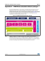
STM32Cube Embedded Software package . . . . . . . . . . . . . . . . . . . . . . . . . . . . . . . . . . . 136
DocID025776 Rev 4
UM1718
1
STM32Cube overview
STM32Cube overview
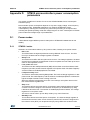
STMCube™ is an STMicroelectronics original initiative to ease developers life by reducing
development efforts, time and cost. STM32Cube covers STM32 portfolio.
STM32Cube includes:
•
The STM32CubeMX, a graphical software configuration tool that allows to generate C
initialization C code using graphical wizards.
•
A comprehensive embedded software platform, delivered per series (such as
STM32CubeF2 for STM32F2 series and STM32CubeF4 for STM32F4 series)
–
The STM32Cube HAL, an STM32 abstraction layer embedded software, ensuring
maximized portability across STM32 portfolio
–
A consistent set of middleware components such as RTOS, USB, TCP/IP,
Graphics
–
All embedded software utilities coming with a full set of examples.
DocID025776 Rev 4
11/140
139
Getting started with STM32CubeMX
UM1718
2
Getting started with STM32CubeMX
2.1
Principles
Customers need to quickly identify the MCU that best meets their requirements (core
architecture, features, memory size, performance…). While board designers main concerns
are to optimize the microcontroller pin configuration for their board layout and to fulfill the
application requirements (choice of peripherals operating modes), embedded system
developer are more interested developing new applications for a specific target device, and
migrating existing designs to different microcontrollers.
The time taken to migrate to new platforms and update the C code to new firmware drivers
adds unnecessary delays to the project. STM32CubeMX was developed within STM32Cube
initiative which purpose is to meet customer key requirements to maximize software reuse
and minimize the time to create the target system:
•
Software reuse and application design portability are achieved through STM32Cube
firmware solution proposing a common Hardware Abstraction Layer API across STM32
portfolio.
•
Optimized migration time is achieved thanks to STM32CubeMX built-in knowledge of
STM32 microcontrollers, peripherals and middleware (LwIP and USB communication
protocol stacks, FATFS file system for small embedded systems, FreeRTOS).
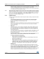
STM32CubeMX graphical interface performs the following functions:
•
Fast and easy configuration of the MCU pins, clock tree and operating modes for the
selected peripherals and middleware
•
Generation of pin configuration report for board designers
•
Generation of a complete project with all the necessary libraries and initialization C
code to set up the device in the user defined operating mode. The project can be
directly imported in the selected application development environment (for a selection
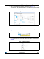
of supported IDEs) to proceed with application development (see Figure 1).
During the configuration process, STM32CubeMX detects conflicts and invalid settings and
highlights them through meaningful icons and useful tool tips.
12/140
DocID025776 Rev 4
UM1718
Getting started with STM32CubeMX
Figure 1. Overview of STM32CubeMX C code generation flow
DocID025776 Rev 4
13/140
139
Getting started with STM32CubeMX
2.2
UM1718
Key features
STM32CubeMX comes with the following features:
•
Project management
STM32CubeMX allows creating, saving and loading previously saved projects:
–
When STM32CubeMX is launched, the user can choose to create a new project or
to load a previously saved project.
–
Saving the project saves user settings and configuration performed within the
project in an .ioc file that will be used the next time the project will be loaded in
STM32CubeMX.
STM32CubeMX projects come in two flavors:
•
–
MCU configuration only: .ioc file can be saved anywhere
–
MCU configuration with C code generation: in this case .ioc files are saved in a
project dedicated folder along with the generated source C code.
Easy MCU and STMicroelectronics board selection
When starting a new project, a dedicated window opens to select either a
microcontroller or an STMicroelectronics board from STM32 portfolio. The MCU
selector allows filtering on series, lines, package types and peripherals.
•
•
Easy pinout configuration
–
From the Pinout view, the user can select the peripherals from a list and configure
the peripheral modes required for the application. STM32CubeMX assigns and
configures the pins accordingly.
–
For more advanced users, it is also possible to directly map a peripheral function
to a physical pin using the Chip view. The signals can be locked on pins to prevent
STM32CubeMX conflict solver from moving the signal to another pin.
–
Pinout configuration can be exported as a .csv file.
Pinout initialization C code generation for STM32L1 and STM32F1 series
The initialization C code generation is based on STM32 standard peripheral firmware
libraries available for download from http://www.st.com.
•
Complete project generation for STM32F0, STM32F2, STM32F3, STM32F4 and
STM32L0 series only (support for STM32F1 and STM32L1 series under
development)
The project generation includes pinout, firmware and middleware initialization C code
for a set of IDEs. It is based on STM32Cube embedded software libraries. The
following actions can be performed:
14/140
–
Starting from the previously defined pinout, the user can proceed with the
configuration of middleware, clock tree, services (RNG, CRC, etc...) and IP
peripheral parameters. STM32CubeMX generates the corresponding initialization
C code.
–
The result is a project directory including generated main.c file and C header files
for configuration and initialization, plus a copy of the necessary HAL and
middleware libraries as well as specific files for the selected IDE.
–
The user can modify the generated source files by adding user-defined C code in
user dedicated sections. STM32CubeMX ensures that the user C code is
DocID025776 Rev 4
UM1718
Getting started with STM32CubeMX
preserved upon next C code generation (the user C code is commented if it is no
longer relevant for the current configuration).
–
•
From the Project settings menu, the user can select the development tool chain
(IDE) for which the C code has to be generated. STM32CubeMX ensures that the
IDE relevant project files are added to the project folder so that the project can be
directly imported as a new project within third party IDE (IAR™, Keil™,…).
Power consumption calculation for STM32F0, STM32F2, STM32F3, STM32F4 and
STM32L0 and STM32L1 series only (support for other series under development)
Starting with the selection of a microcontroller part number and a battery type, the user
can define a sequence of steps representing the application life cycle and parameters
(choice of frequencies, enabled peripherals, step duration). STM32CubeMX power
consumption calculator returns the corresponding power consumption and battery life
estimates.
•
Clock tree configuration for STM32F0, STM32F2, STM32F3, STM32F4 and
STM32L0 series only
STM32CubeMX offers a graphical representation of the clock tree as it can be found in
the device reference manual. The user can change the default settings (clock sources,
prescaler and frequency values). The clock tree will be updated accordingly. Invalid
settings and limitations are highlighted and documented with tool tips.
•
Automatic updates of STM32CubeMX and STM32Cube firmware packages
STM32CubeMX comes with an updater mechanism that can be configured for
automatic or on-demand check for updates. It supports STM32CubeMX self-updates
as well as STM32Cube firmware library package updates.
•
Report generation
.pdf and .csv reports can be generated to document user configuration work.
2.3
Rules and limitations
•
C code generation for STM32F0, STM32F2, STM32F3, STM32F4 and STM32L0
series covers only peripheral and middleware initialization. It is based on STM32Cube
HAL firmware libraries.
•
C code generation for STM32L1 and STM32F1 series covers only GPIO initialization. It
is based on standard peripheral firmware libraries. A complete C code generation
solution will be offered within the further deployment of STM32Cube initiative to all
STM32 series.
•
Power consumption calculation is supported for STM32F0, STM32F2, STM32F3,
STM32F4 and STM32L0 and STM32L1 series only. Power consumption calculation for
other series will be progressively offered within further deployment of STM32Cube
initiative to all STM32 series.
•
STM32CubeMX configuration files (.ioc extension) can be saved in the same folder
when they target configuration only but require a dedicated folder when they cover
configuration for C code generation.
•
Refer to Appendix A for a description of pin assignment rules.
•
Refer to Appendix B for a description of STM32CubeMX C code generation design
choices and limitations.
DocID025776 Rev 4
15/140
139
Installing and running STM32CubeMX
UM1718
3
Installing and running STM32CubeMX
3.1
System requirements
3.1.1
Supported operating systems and architectures
•
•
•
3.1.2
Windows® 7: 32-bit (x86), 64-bit (x64)
Windows® 8: 32-bit (x86), 64-bit (x64)
Memory prerequisites
•
3.1.3
Windows® XP: 32-bit (x86)
Recommended minimum RAM: 2 Gbytes.
Software requirements
The following software must be installed:
•
Java Run Time Environment 1.7 (version 1.7_45 or newer)
If Java is not installed on your computer or if you have an old version, STM32CubeMX
installer will open the Java download webpage and stop.
•
For Eclipse plug-in installation only, install one of the following IDE:
–
Eclipse IDE Juno (4.2)
–
Eclipse IDE Indigo (3.7)
–
Eclipse IDE Helios (3.6)
3.2
Installing/uninstalling STM32CubeMX standalone version
3.2.1
Installing STM32CubeMX standalone version
To install STM32CubeMX, follow the steps below:
Note:
16/140
1.
Download the latest STM32CubeMX installation package from
http://www.st.com/stm32cube.
2.
Download STM32CubeMX-setup.zip to your local disk and extract the STM32CubeMXsetup.exe file.
3.
Double-click STM32CubeMX-setup.exe to launch the installation wizard.
4.
If the proper version of the Java Runtime Environment (version 1.7_45 or newer) is not
installed, the wizard will propose to download it and stop. Restart STM32CubeMX
installation once Java installation is complete. Refer to Section 9: FAQ for issues when
installing the JRE.
5.
If the installation was successful, the STM32CubeMX icon is displayed on the desktop
and STM32CubeMX application is available from the Program menu. STM32CubeMX
.ioc files are displayed with a cube icon and double-clicking them opens up them using
STM32CubeMX.
Only the latest installation of STM32CubeMX will be enabled in the program menu. Previous
versions can be kept on your PC even (not recommended) when different installation folders
have been selected. Otherwise, the new installation overwrites the previous ones.
DocID025776 Rev 4
UM1718
3.2.2
Installing and running STM32CubeMX
Uninstalling STM32CubeMX standalone version
To uninstall STM32CubeMX, follow the steps below:
1.
Open the Windows Control panel.
2.
Select Programs and Features to display the list of programs installed on your
computer.
3.
Right click on STM32CubeMX and select the uninstall function.
An alternate solution could be:
3.3
1.
From the Program menu, go to STM32CubeMX folder.
2.
Launch Uninstall STM32CubeMX.
Installing STM32CubeMX plug-in version
STM32CubeMX plug-in can be installed within Eclipse IDE development tool chain.
Installation related procedures are described in this section.
3.3.1
Downloading STM32CubeMX plug-in installation package
To download STM32CubeMX plug-in, follow the sequence below:
3.3.2
1.
Go to http://www.st.com/stm32cube.
2.
Download STM32CubeMX- Eclipse-plug-in .zip file to your local disk.
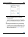
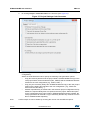
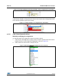
Installing STM32CubeMX as an Eclipse IDE plug-in
To install STM32CubeMX as an Eclipse IDE plug-in, follow the sequence below:
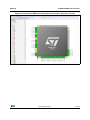
1.
Launch the Eclipse environment.
2.
Select Help > Install New Software from the main menu bar. The Available Software
window appears.
3.
Click Add. The Add Repository window opens.
4.
Click Archive. The Repository archive browser opens.
5.
Select the STM32CubeMX- Eclipse-plug-in .zip file that you downloaded and click
Open (see Figure 2).
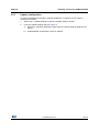
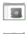
6.
Click OK in the Add Repository dialog box,
7.
Check STM32CubeMX_Eclipse_plug-in and click Next (see Figure 3).
8.
Click Next in the Install Details dialog box.
9.
Click ”I accept the terms of the license agreement” in the Review Licenses dialog box
and then click Finish.
10. Click OK in the Security Warning menu.
11. Click OK when requested to restart Eclipse IDE (see Section 3.4.2: Running
STM32CubeMX plug-in from Eclipse IDE).
DocID025776 Rev 4
17/140
139
Installing and running STM32CubeMX
UM1718
Figure 2. Adding STM32CubeMX plug-in archive
Figure 3. Installing STM32CubeMX plug-in
18/140
DocID025776 Rev 4
UM1718
3.3.3
Installing and running STM32CubeMX
Uninstalling STM32CubeMX as an Eclipse IDE plug-in
To uninstall STM32CubeMX plug-in in Eclipse IDE, follow the sequence below:
1.
In Eclipse, right-click STM32CubeMX perspective Icon (see Figure 4) and select Close.
2.
From Eclipse Help menu, select Install New Software.
3.
Click the Installed Software tab, then select STM32CubeMX and click Uninstall.
4.
Click Finish in the Uninstall Details menu (see Figure 5).
Figure 4. Closing STM32CubeMX perspective
Figure 5. Uninstalling STM32CubeMX plug-in
DocID025776 Rev 4
19/140
139
Installing and running STM32CubeMX
UM1718
3.4
Launching STM32CubeMX
3.4.1
Running STM32CubeMX as standalone application
To run STM32CubeMX as a standalone application:
3.4.2
•
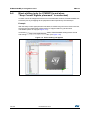
Select STM32CubeMX from Program Files > ST Microelectronics > STM32CubeMX.
•
Or double-click STM32CubeMX icon on your desktop.
Running STM32CubeMX plug-in from Eclipse IDE
To run STM32CubeMX plug-in from Eclipse:
1.
Launch Eclipse environment.
2.
Once Eclipse IDE is open, click open new perspective:
3.
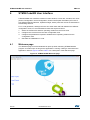
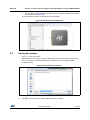
Select STM32CubeMX to open STM32CubeMX as a perspective (see Figure 6).
4.
STM32CubeMX perspective opens (see Figure 7). Enter STM32CubeMX user
interface via the Welcome menus.
Figure 6. Opening Eclipse plug-in
20/140
.
DocID025776 Rev 4
UM1718
Installing and running STM32CubeMX
Figure 7. STM32CubeMX perspective
3.5
Getting STM32Cube updates
STM32CubeMX implements a mechanism to access the internet and to:
•
Perform self-updates of STM32CubeMX and of the STM32Cube firmware packages
installed on the user computer
•
Download new firmware packages and patches
Installation and update related sub-menus are available under the Help menu.
If the PC on which STM32CubeMX runs is connected to a computer network using a proxy
server, STM32CubeMX needs to connect to that server to access the internet, get selfupdates and download firmware packages. Refer to Section 3.5.1: Updater configuration for
a description of this connection configuration.
To view Windows default proxy settings, select Internet options from the Control panel and
select LAN settings from the Connections tab (see Figure 8).
DocID025776 Rev 4
21/140
139
Installing and running STM32CubeMX
UM1718
Figure 8. Displaying Windows default proxy settings
Several proxy types exist and different computer network configurations are possible:
•
Without proxy: the application directly accesses the web (Windows default
configuration).
•
Proxy without login/password
•
Proxy with login/password: when using an internet browser, a dialog box opens and
prompts the user to enter his login/password.
•
Web proxies with login/password: when using an internet browser, a web page opens
and prompts the user to enter his login/password.
If necessary, contact your IT administrator for proxy information (proxy type, http address,
port).
STM32CubeMX does not support web proxies. In this case, the user will not be able to
benefit from the update mechanism and will need to manually copy the STM32 firmware
packages from http://www.st.com/stm32cube to the repository. To do it, follow the sequence
below:
22/140
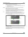
1.
Go to http://www.st.com/stm32cube and download the relevant STM32Cube firmware
package from the Associated Software section.
2.
Unzip the zip package to your STM32Cube repository. Find out the default repository
folder location in the Updater settings tab as shown in Figure 9 (you might need to
update it to use a different location or name).
DocID025776 Rev 4
UM1718
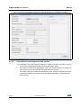
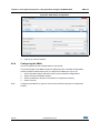
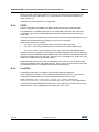
3.5.1
Installing and running STM32CubeMX
Updater configuration
To perform STM32Cube new library package installation or updates, the tool must be
configured as follows:
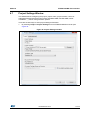
1.
Select Help > Updater Settings to open the Updater Settings window.
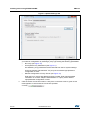
2.
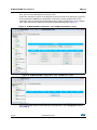
From the Updater Settings tab (see Figure 9)
a)
Specify the repository destination folder where the downloaded packages will be
stored.
b)
Enable/Disable the automatic check for updates.
DocID025776 Rev 4
23/140
139
Installing and running STM32CubeMX
UM1718
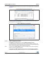
Figure 9. Updater Settings tab
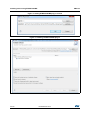
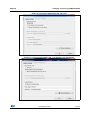
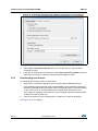
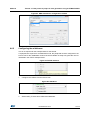
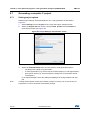
3.
In the Connection Parameters tab, specify the proxy server settings appropriate for
your network configuration by selecting a proxy type among the following possibilities:
–
No Proxy (see Figure 10)
–
Use System Proxy Parameters (see Figure 11)
On Windows, proxy parameters will be retrieved from the PC system settings.
Uncheck “Require Authentication” if a proxy server without login/password
configuration is used.
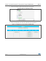
–
Manual Configuration of Proxy Server (see Figure 12)
Enter the Proxy server http address and port number. Enter login/password
information or uncheck “Require Authentication” if a proxy server without
login/password configuration is used.
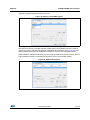
4.
24/140
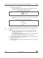
Click the Check Connection button to verify if the connection works. A green check
mark appears to confirm that the connection operates
correctly
:
DocID025776 Rev 4
UM1718
Installing and running STM32CubeMX
Figure 10. Connection Parameters tab - No proxy
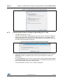
Figure 11. Connection Parameters tab - Use System proxy parameters
DocID025776 Rev 4
25/140
139
Installing and running STM32CubeMX
UM1718
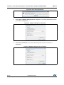
Figure 12. Connection Parameters tab - Manual Configuration of Proxy Server
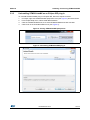
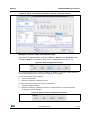
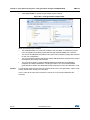
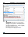
3.5.2
5.
Select Help > Install New Libraries sub-menu to select among a list of possible
packages to install.
6.
If the tool is configured for manual checks, select Help > Check for Updates to find out
about new tool versions or firmware library patches available to install.
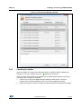
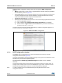
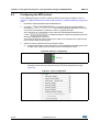
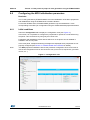
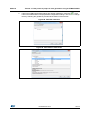
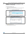
Downloading new libraries
To download new libraries, follow the steps below:
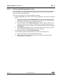
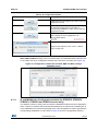
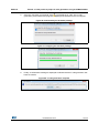
1.
Select Help > Install New Libraries to open the New Libraries Manager window.
If the installation was performed using STM32CubeMX, all the packages available for
download are displayed along with their version including the version currently installed
on the user PC (if any), and the latest version available from http://www.st.com.
The package is marked in green when the version installed matches the latest version
available from http://www.st.com.
2.
Click the checkbox to select a package then “Install Now” to start the download.
See Figure 13 for an example.
26/140
DocID025776 Rev 4
UM1718
Installing and running STM32CubeMX
Figure 13. New Libraires Manager window
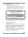
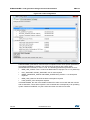
3.5.3
Checking for updates
When the updater is configured for automatic checks, it regularly verifies if updates are
available. In this case, a green arrow icon
appears on the tool bar.
When automatic checks have been disabled in the updater settings window, the user can
manually check if updates are available:
1.
Click the icon to open the Update Manager window or Select Help > Check for
Updates. All the updates available for the user current installation are listed.
2.
Click the check box to select a package, and then Install Now to download the update.
DocID025776 Rev 4
27/140
139
STM32CubeMX User Interface
4
UM1718
STM32CubeMX User Interface
STM32CubeMX user interface consists of a main window, a menu bar, a toolbar, four views
(Pinout, Configuration, Clock Configuration, Power Consumption Calculator) and a set of
help windows (MCUs selection, Update manager, About). All these menus are described in
the following sections.
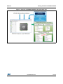
For C code generation, although the user can switch back and forth between the different
configuration views, it is recommended to follow the sequence below:
4.1
1.
Select the relevant IPs and their operating modes from the Pinout view
2.
Configure the clock tree from the clock configuration view
3.
Configure the parameters required to initialize the IP operating modes from the
configuration view.
4.
Generate the initialization C code.
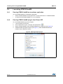
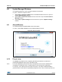
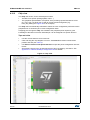
Welcome page
The Welcome page is the first window that opens up when launching STM32CubeMX
program. It remains open as long as the application is running. Closing it closes down the
application. Refer to Figure 14 and to Table 1 for a description of the Welcome page.
Figure 14. STM32CubeMX Welcome page
28/140
DocID025776 Rev 4
UM1718
STM32CubeMX User Interface
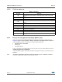
Table 1. Welcome page shortcuts
Name
New Project
Launches STM32CubeMX new project creation by opening the New
project window (select an MCU from the MCU selector tab or a board
configuration from the Board selector tab).
Load Project
Opens a browser window to select a previously saved configuration (.ioc
file) and loads it.
Help
4.2
Description
Opens the user manual.
New project window
This window shows two tabs to choose from:
•
The MCU selector tab offering a list of target processors, peripherals and packages
•
A Board Selector tab showing a list of STMicrolelectronics boards.
The MCU selector allows filtering on 4 different criteria: series, lines, packages and
peripherals (see Figure 15).
When a board is selected, the Pinout view is initialized with the board default MCU and
pinout configuration (see Figure 17). Optionally, the user can choose to initialize it with the
default peripheral modes (see Figure 18).
When a board configuration is selected, the signals change to 'pinned', i.e. they cannot be
moved automatically by STM32CubeMX constraint solver (user action on the peripheral
tree, such as the selection of a peripheral mode, will not move the signals). This ensures
that the user configuration remains compatible with the board.
DocID025776 Rev 4
29/140
139
STM32CubeMX User Interface
UM1718
Figure 15. New Project window
30/140
DocID025776 Rev 4
UM1718
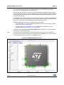
4.3
STM32CubeMX User Interface
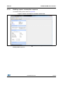
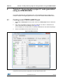
Main window
Once an STM32 part number or a board has been selected or a previously saved project
has been loaded, the main window displays all STM32CubeMX components and menus
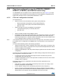
(see Figure 16). Refer to Section 4.3 for a detailed description of the toolbar and menus.
Figure 16. STM32CubeMX Main window upon MCU selection
DocID025776 Rev 4
31/140
139
STM32CubeMX User Interface
UM1718
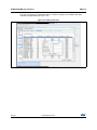
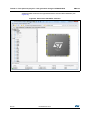
Selecting a board while keeping the peripheral default modes option unchecked,
automatically sets the pinout for this board. However, no peripheral modes are set. The user
can then manually select from the peripheral tree the peripheral modes required for his
application (see Figure 17).
Figure 17. STM32CubeMX Main window upon board selection
(Peripheral default option unchecked)
32/140
DocID025776 Rev 4
UM1718
STM32CubeMX User Interface
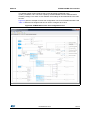
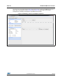
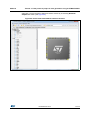
Selecting a board with the peripheral default modes option checked, automatically sets both
the pinout and the default modes for the peripherals available on the board. This means that
STM32CubeMX will generate the C initialization code for all the peripherals available on the
board and not only for those relevant to the user application (see Figure 18).
Figure 18. STM32CubeMX Main window upon board selection
(Peripheral default option checked)
4.4
Toolbar and menus
The following menus are available from STM32CubeMX menu bar:
•
File menu
•
Project menu
•
Pinout menu (displayed only when the Pinout view has been selected)
•
Window menu
•
Help menu
STM32CubeMX menus and toolbars are described in the sections below.
DocID025776 Rev 4
33/140
139
STM32CubeMX User Interface
4.4.1
UM1718
File menu
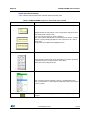
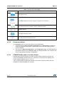
Refer to Table 2 for a description of the File menu and icons.
Table 2. File menu functions
Icon
4.4.2
Name
Description
New Project
Opens a new project window showing all supported MCUs and
well as a set of STMicroelectronics boards to choose from
Load Project
…
Loads an existing STM32CubeMX project configuration by
selecting an STM32CubeMX configuration .ioc file.
Save Project
as …
Saves current project configuration (pinout, clock tree, IP, PCC) as
a new project. This action creates an .ioc file with user defined
name and located in the destination folder
Save Project
Saves current project
No icon
Close Project
Closes current project and switch back to the welcome page
No icon
Recent
Projects >
No icon
Exit
Displays the list of five most recently saved projects
Proposes to save the project if needed then close the application
Project menu
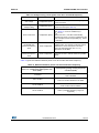
Refer to Table 3 for a description of the Project menu and icons.
Table 3. Project menu
Icon
Name
Description
Generate C
code
Generates C initialization C code for current configuration
(pinout, clocks, peripherals and middleware). Opens a window
for project settings if they have not been defined previously.
Generate
report(1)
Generates current project configuration as a pdf file and a text
file.
Settings
Opens the project settings window to configure project name,
folder, select a toolchain and C code generation options
1. If the project was previously saved, the reports are generated at the same location as the project
configuration .ioc file. Otherwise, the user can choose the destination folder, and whether to save the
project configuration as an .ioc file or not.
34/140
DocID025776 Rev 4
UM1718
4.4.3
STM32CubeMX User Interface
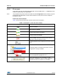
Pinout menu
The Pinout menu and sub-menus shortcuts are available only when the Pinout tab is
selected (see Figure 19). They are hidden otherwise (see Figure 20). Refer to Table 4 for a
description of the Pinout menu and icons.
Figure 19. Pinout menus (Pinout tab selected)
Figure 20. Pinout menus (Pinout tab not selected)
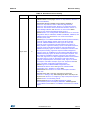
Table 4. Pinout menu
Icon
No icon
Name
Description
Undo
Undoes last configuration steps (one by one)
Redo
Redoes steps that have been undone (one by one)
Pins/Signals
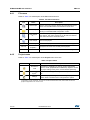
Options
Opens a window showing the list of all the configured pins
together with the name of the signal on the pin and a Label field
allowing the user to specify a label name for each pin of the list.
For this menu to be active, at least one pin must have been
configured.
Click the pin icon to pin/unpin signals individually.
Select multiple rows then right click to open contextual menu
and select action to pin or unpin all selected signals at once.
Click column header names to sort alphabetically by name or
according to placement on MCU.
Pinout search
field
Allows the user to search for a pin name, signal name or signal
label in the Pinout view. When it is found, the pin or set of pins
that matches the search criteria blinks on the chip view. Click
the chip view to stop blinking.
Show user
labels
Allows showing on the chip view, the user-defined labels
instead of the names of the signals assigned to the pins.
DocID025776 Rev 4
35/140
139
STM32CubeMX User Interface
UM1718
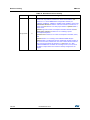
Table 4. Pinout menu (continued)
Icon
Name
Description
No icon
Clear Pinouts
Clears user pinout configuration in the Pinout window. Note that
this action clears from the configuration window the IPs that
have an influence on the pinout.
Clear Single
Clears signal assignments to pins for signals that have no
Mapped Signals associated mode (highlighted in orange and not pinned).
No icon
No icon
Set unused
GPIOs
Opens a window to specify the number of GPIOs to be
configure among the total number of GPIO pins that are not
used yet. Specify their mode: Input, Output or Analog
(recommended configuration to optimize power consumption).
No icon
Reset used
GPIOs
Opens a window to specify the number of GPIOs to be freed
among the total number of GPIO pins that are configured.
Generate csv
text pinout file
Collapse All
Generates pin configuration as a .csv text file
Collapses the IP / Middleware tree view
Resets to “Disabled” all peripherals and middleware modes that
have been enabled. The pins configured in these modes (green
Disable Modes color) are consequently reset to “Unused” (gray color). IPs and
middleware labels change from green to black (when unused)
or gray (when not available).
Expand All
Expands the IP/Middleware tree view to display all functional
modes.
Zooming in
Zooms in the chip pinout diagram
Best Fit
4.4.4
Adjusts the chip pinout diagram to the best fit size
Zooming out
Zooms out the chip pinout diagram
Keep current
signals
Placement
Available from toolbar only.
Prevents moving pin assignments to match a new IP operating
mode. It is recommended to use the new pinning feature that
can block each pin assignment individually and leave this
checkbox unchecked.
Window menu
The window menu allows to access the Outputs function (see Table 5).
Table 5. Window menu
Name
Outputs
36/140
Description
Opens the MCUs selection window at the bottom of STM32CubeMX Main
window.
DocID025776 Rev 4
UM1718
4.4.5
STM32CubeMX User Interface
Help menu
Refer to Table 6 for a description of the Help menu and icons.
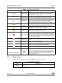
Table 6. Help menu
Icons
Name
Description
Help Content
Opens the STM32CubeMX user manual
About...
Shows version information
Check for Updates
Shows the software and firmware release updates available for
download.
Shows all STM32CubeMX and firmware releases available for
Install New Libraries installation. Green check box indicates which ones are already
installed on you PC and up-to-date.
Updater Settings...
4.5
Opens the updater settings window to configure manual
versus automatic updates, proxy settings for internet
connections, repository folder where the downloaded software
and firmware releases will be stored.
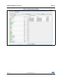
MCUs selection window
This window lists all the MCUs of a given family that match the user criteria (series,
peripherals, package..) when an MCU was selected last.
Note:
Selecting a different MCU from the list resets the current project configuration and switches
to the new MCU. The user will be prompted to confirm this action before proceeding.
Figure 21. MCU selection menu
DocID025776 Rev 4
37/140
139
STM32CubeMX User Interface
UM1718
This window can be shown/hidden by selecting/unselecting Outputs from the Window
menu.
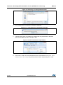
4.6
Set unused / Reset used GPIOs windows
These windows allow configuring several pins at a time in the same GPIO mode.
To open them:
•
Note:
Select Pinout > Set unused GPIOs from the STM32CubeMX menu bar.
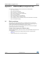
The user selects the number of GPIOs and lets STM32CubeMX choose the actual pins to
be configured or reset, among the available ones.
Figure 22. Set unused pins window
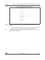
•
Select Pinout > Reset used GPIOs from the STM32CubeMX menu bar.
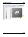
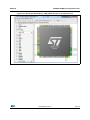
Depending whether the Keep Current Signals Placement option is checked or not on
the toolbar, STM32CubeMX conflict solver will be able to move or not the GPIO signals
to other unused GPIOs:
–
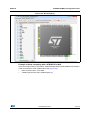
When Keep Current Signals Placement is off (unchecked), STM32CubeMX
conflict solver can move the GPIO signals to unused pins in order to fit in another
peripheral mode.
–
When Keep Current Signals Placement is on (checked), GPIO signals will not be
moved and the number of possible peripheral modes becomes limited.
Refer to Figure 24 and Figure 25 and check the limitation in available peripheral
modes.
Figure 23. Reset used pins window
38/140
DocID025776 Rev 4
UM1718
STM32CubeMX User Interface
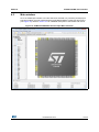
Figure 24. Set unused GPIO pins with Keep Current Signals Placement checked
DocID025776 Rev 4
39/140
139
STM32CubeMX User Interface
UM1718
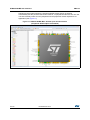
Figure 25. Set unused GPIO pins with Keep Current Signals Placement unchecked
40/140
DocID025776 Rev 4
UM1718
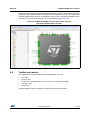
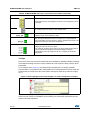
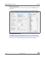
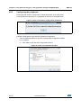
4.7
STM32CubeMX User Interface
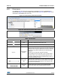
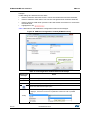
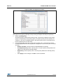
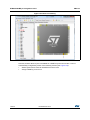
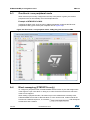
Project Settings Window
This window allows configuring the project: project name, project location, choice of
Integrated Development Environment tools (Keil MDK-ARM, IAR EW-ARM, Attolic
TrueStudio,…), and C code generation options.
There are several ways to enter project settings information:
1.
By selecting Project > Project Settings from the STM32CubeMX menu bar (see
Figure 26.
Figure 26. Project Settings window
DocID025776 Rev 4
41/140
139
STM32CubeMX User Interface
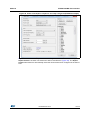
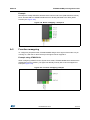
2.
UM1718
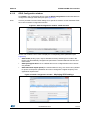
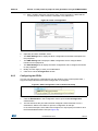
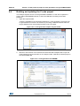
BY clicking Project > Generate code for the first time (see Figure 27).
Figure 27. Project Settings Code Generator
3.
By selecting Save As for a project that includes C code generation (and not only pin
configuration).
Select the Code Generator tab to specify the following code generation options.
Note:
42/140
–
Copy all necessary libraries into the project folder: STM32CubeMX will copy to the
user project folder, the drivers libraries (HAL, CMSIS) and the middleware libraries
relevant to the user configuration (e.g. FATFS, USB, ..).
–
Copy only the necessary library files: STM32CubeMX will copy to the user project
folder only the library files relevant to the user configuration (e.g., SDIO HAL
driver from the HAL library,…).
–
Add the required library as referenced in the toolchain project configuration file. By
default, the required library files are copied to the user project. Select this option
for the configuration file to point to files in STM32CubeMX repository instead: the
user project folder will not hold a copy of the library files but only a reference to the
files in STM32CubeMX repository.
Useful tooltips are also available by hovering the mouse over the different options.
DocID025776 Rev 4
UM1718
4.8
STM32CubeMX User Interface
Update Manager Windows
This window displays the current updates available for download.
To open it, follow the sequence below:
4.9
1.
Select Help > Check for updates from the STM32CubeMX menu bar to open the
Check Update Manager window.
2.
Select Help > Install new libraries from the menu bar to open the New Libraries
Manager window.
3.
Select Help > Update settings from the menu bar to open the Updater settings
window.
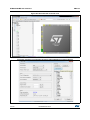
About Window
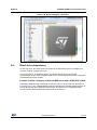
This window displays STM32CubeMX version information.
To open it, select Help > About from the STM32CubeMX menu bar.
Figure 28. About window
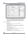
4.10
Pinout view
The Pinout view helps the user configuring the MCU pins based on a selection of
peripherals/middleware and of their operating modes.
Note:
For some middleware (USB, FATS, LwIP), a peripheral mode must be enabled before
activating the middleware mode. Tooltips guide the user through the configuration.
For FATFS, a user-defined mode has been introduced. This allows STM32CubeMX to
generate FATFS code without an predefined peripheral mode. Then, it will be up to the user
DocID025776 Rev 4
43/140
139
STM32CubeMX User Interface
UM1718
to connect the middleware with a user-defined peripheral by updating the generated
user_sdio.c/.h driver files with the necessary code.
Since STM32 MCUs allow a same pin to be used by different peripherals and for several
functions (alternate functions), the tool searches for the pinout configuration that best fits the
set of peripherals selected by the user. STM32CubeMX highlights the conflicts that cannot
be solved automatically.
The Pinout view left panel shows the IP tree and the right pane, a graphical representation
of the pinout for the selected package (e.g. BGA, QFP...) where each pin is represented with
its name (e.g. PC4) and its current alternate function assignment if any.
STM32CubeMX offers two ways to configure the microcontroller:
•
From the IP tree by clicking the peripheral names and selecting the operating modes
(see Section 4.10.1: IP tree pane).
•
For advanced users, by clicking a pin on the Chip view to manually map it to a
peripheral function (see Section 4.10.2: Chip view).
In addition, selecting Pinout > Set unused GPIOs allows configuring in one shot several
unused pins in a given GPIO mode.
Note:
The Pinout view is automatically refreshed to display the resulting pinout configuration.
Pinout relevant menus and shortcuts are available when the Pinout view is active (see the
menu dedicated sections for details on the Pinout menus).
Figure 29. STM32CubeMX Pinout view
44/140
DocID025776 Rev 4
UM1718
4.10.1
STM32CubeMX User Interface
IP tree pane
In this pane, the user can select the peripherals, services (DMA, RCC,...), middleware in the
modes corresponding to the application.
Note:
The peripheral tree panel is also accessible from the Configuration view. However, only the
peripherals and middleware modes without influence on the pinout can be configured
through this menu.
Icons and color schemes
Table 7 shows the icons and color scheme used in the IP tree pane.
Table 7. IP tree pane - icons and color scheme
Display
Peripheral status
The peripheral is not configured (no mode is set) and all
modes are available.
The peripheral is configured (at least one mode is set) and all
other modes are available
The peripheral is configured (one mode is set) and at least
one of its other modes is unavailable.
The peripheral is not configured (no mode is set) and at least
one of its modes is unavailable.
The peripheral is not configured (no mode is set) and no
mode is available. Move the mouse over the IP name to
display the tooltip describing the conflict.
Available peripheral mode configurations are shown in plain
black.
The warning yellow icon indicates that at least one mode
configuration is no longer available.
When no more configurations are left for a given peripheral
mode, this peripheral is highlighted in red.
Some modes depends on the configuration of other
peripherals or middleware modes. A tooltip explains the
dependencies when the conditions are not fulfilled.
DocID025776 Rev 4
45/140
139
STM32CubeMX User Interface
4.10.2
UM1718
Chip view
The Chip view shows, for the selected part number:
•
The MCU in a specific package (BGA, LQFP…)
•
The graphical representation of its pinout, each pin being represented with its name
(e.g. PC4: pin 4 of GPIO port C) and its current function assignment (e.g.
ETH_MII_RXD0) (see Figure 30 for an example).
The Chip view is automatically refreshed to match the user configuration performed via the
peripheral tree. It shows the pins current configuration state.
Assigning pins through the Chip view instead of the peripheral pane requires a good
knowledge of the MCU since each individual pin can be assigned to a specific function.
Tips and tricks
•
Use the mouse wheel to zoom in and out.
•
Click and drag the chip diagram to move it. Click best fit to reset it to best suited
position and size (see Table 4).
•
Use Pinout > Generic CSV pinout text file to export the pinout configuration into text
format.
•
Some basic controls, such as insuring blocks of pins consistency, are built-in. See
Appendix A: STM32CubeMX pin assignment rules for details.
Figure 30. Chip view
46/140
DocID025776 Rev 4
UM1718
STM32CubeMX User Interface
Icons and color schemes
Table 8 shows the icons and color scheme used in the Chip view.
Table 8. STM32CubeMX Chip view - Icons and color scheme
Display
Pin information
Tooltip indicates the selected pin current configuration: alternate function
name, Reset state or GPIO mode.
Move your mouse over the pin name to display it.
When a pin features alternate pins corresponding to the function currently
selected, a popup message prompts the user to perform a ctrl + click to
display them.
The alternate pins available are highlighted in blue.
List of alternate functions that can be selected for a given pin. By default,
no alternate function is configured (pin in reset state).
Click the pin name to display the list.
When a function has been mapped to the pin, it is highlighted in blue.
When it corresponds to a well configured peripheral mode, the list caption
is shown in green.
Boot and reset pins are highlighted in khaki. Their configuration cannot be
changed.
DocID025776 Rev 4
47/140
139
STM32CubeMX User Interface
UM1718
Table 8. STM32CubeMX Chip view - Icons and color scheme (continued)
Display
Pin information
Power dedicated pins are highlighted in yellow. Their configuration cannot
be changed.
Non-configured pins are shown in gray (default state).
When a signal assignment corresponds to a peripheral mode without
ambiguity, the pin color switches to green.
When the signal assignment does not correspond to a valid peripheral
mode configuration, the pin is shown in orange. Additional pins need to be
configured to achieve a valid mode configuration.
When a signal assignment corresponds to a peripheral mode without
ambiguity, the pins are shown in green.
As an example, assigning the PF2 pin to the I2C2_SMBA signal matches
to I2C2 mode without ambiguity and STM32CubeMX configures
automatically the other pins (PF0 and PF1) to complete the pin mode
configuration.
Tooltips
Move the mouse over IPs and IP modes that are unavailable or partially available to display
the tooltips describing the source of the conflict that is which pins are being used by which
peripherals.
As an example (see Figure 31), the Ethernet (ETH) peripheral is no longer available
because there is no possible mode configuration left. A tooltip indicates to which signal are
assigned the pins required for this mode (ADC1-IN0 signal, USART3 synchronous signal,
etc...).
Figure 31. Red highlights and tooltip example: no mode configuration available
In the next example (see Figure 32), the SDIO peripheral is partially available because at
least one of its modes is unavailable: the necessary pins are already assigned to the I2C
mode of the I2C3 peripheral.
48/140
DocID025776 Rev 4
UM1718
STM32CubeMX User Interface
Figure 32. Orange highlight and tooltip example: some configurations unavailable
In this last example (see Figure 33) I2C2 peripheral is unavailable because there is no
mode function available. A tooltip shows for each function where all the remapped pins have
been allocated (USART3 synchronous mode).
Figure 33. Tooltip example: all configurations unavailable
4.10.3
Chip view advanced actions
Manually modifying pin assignments
To manually modify a pin assignment, follow the sequence below:
1.
Click the pin in the Chip view to display the list of all other possible alternate functions
together with the current assignment highlighted in blue (see Figure 34).
2.
Click to select the new function to assign to the pin.
Figure 34. Modifying pin assignments from the chip view
DocID025776 Rev 4
49/140
139
STM32CubeMX User Interface
UM1718
Manually remapping a function to another pin
To manually remap a function to another pin, follow the sequence below:
Caution:
1.
Press the Ctrl key and click the pin in the Chip view. Possible pins for relocation, if any,
are highlighted in blue.
2.
Drag the function to the target pin.
A pin assignment performed from the Chip view overwrites any previous assignment.
Manual remapping with destination pin ambiguity
For MCUs with block of pins consistency (STM32F100x/ F101x/ F102x/ F103x and
STM32F105x/F107x), the destination pin can be ambiguous,e.g. there can be more than
one destination block including the destination pin. To display all the possible alternative
remapping blocks, move the mouse over the target pin.
Note:
A "block of pins" is a group of pins that must be assigned together to achieve a given
peripheral mode. As shown in Figure 35, two blocks of pins are available on a
STM32F107xx MCU to configure the Ethernet Peripheral in RMII synchronous mode: {PC1,
PA1, PA2, PA7, PC4, PC5, PB11, PB12, PB13, PB5} and {PC1, PA1, PA2, PD10, PD9,
PD8, PB11, PB12, PB13, PB5}.
Figure 35. Example of remapping in case of block of pins consistency
Resolving pin conflicts
To resolve the pin conflicts that may occur when some peripheral modes use the same pins,
STM32CubeMX attempts to reassign the peripheral mode functions to other pins. The
peripherals for which pin conflicts could not be solved are highlighted in red or orange with a
tooltip describing the conflict.
50/140
DocID025776 Rev 4
UM1718
STM32CubeMX User Interface
If the conflict cannot be solved by remapping the modes, the user can try the following:
4.10.4
•
If the
different sequence.
•
Uncheck the Keep Current Signals Placement box and let STM32CubeMX try all the
remap combinations to find a solution.
•
Manually remap a mode of a peripheral when you cannot use it because there is no
pin available for one of the signals of that mode.
box is checked, try to select the peripherals in a
Keep Current Signals Placement
This checkbox is available from the toolbar when the Pinout view is selected (see Figure 19
and Table 4). It can be selected or unselected at any time during the configuration. It is
unselected by default.
It is recommended to keep the checkbox unchecked for an optimized placement of the
peripherals (maximum number of peripherals concurrently used).
The Keep Current Signals Placement checkbox should be selected when the objective is
to match a board design.
Keep Current Signals Placement is unchecked
This allows STM32CubeMX to remap previously mapped blocks to other pins in order to
serve a new request (selection of a new IP mode or a new IP mode function) which conflicts
with the current pinout configuration.
Keep Current Signals Placement is checked
This ensures that all the functions corresponding to a given peripheral mode remain
allocated (mapped) to a given pin. Once the allocation is done, STM32CubeMX cannot
move a peripheral mode function from one pin to another. New configuration requests are
served if it is feasible within current pin configuration.
This functionality is useful to:
•
Lock all the pins corresponding to peripherals that have been configured using the
Peripherals panel.
•
Maintain a function mapped to a pin while doing manual remapping from the Chip view.
Tip
If a mode becomes unavailable (highlighted in red), try to find another pin remapping
configuration for this mode by following the steps below:
Note:
1.
From the Chip view, unselect the assigned functions one by one until the mode
becomes available again.
2.
Then, select the mode again and continue the pinout configuration with the new
sequence (see Appendix A: STM32CubeMX pin assignment rules for a remapping
example). This operation being time consuming, it is recommended to unselect the
Keep Current Signals Placement checkbox.
Even if Keep Current Signals placement is unchecked, GPIO_ functions (excepted
GPIO_EXTI functions) are not moved by STM32CubeMX.
DocID025776 Rev 4
51/140
139
STM32CubeMX User Interface
4.10.5
UM1718
Pinning and labeling signals on pins
STM32CubeMX comes with a feature allowing the user to selectively lock (or pin) signals to
pins. This will prevent STM32CubeMX from automatically moving the pinned signals to
other pins when resolving conflicts.
There are several ways to pin, unpin and label the signals:
1.
2.
From the chip view, right-click a pin with a signal assignment. This opens a contextual
menu:
a)
For unpinned signals, select Signal Pinning to pin the signal. A pin icon is then
displayed on the relevant pin. The signal can no longer be moved automatically
(for example when resolving pin assignment conflicts).
b)
For pinned signals, select Signal Unpinning to unpin the signal. The pin icon is
removed. From now on, to resolve a conflict (such as peripheral mode conflict),
this signal can be moved to another pin, provided the Keep user placement option
is unchecked.
c)
Select Enter User Label to specify a user defined label for this signal. The new
label will replacing the default signal name in the chip view.
From the pinout menu, select Pins/Signals Options
The Pins/Signals Options window (see Figure 36) lists all configured pins.
52/140
a)
Click the first column to individually pin/unpin signals.
b)
Select multiple rows and right-click to open the contextual menu and select
Signal(s) Pinning or Unpinning.
DocID025776 Rev 4
UM1718
STM32CubeMX User Interface
Figure 36. Pins/Signals Options window
c)
Select the User Label field to edit the field and enter a user-defined label.
d)
Order list alphabetically by Pin or Signal name by clicking the column header.
Click once more to go back to default i.e. to list ordered according to pin
placement on MCU.
Note:
Even if a signal is pinned, it is still possible however to manually change the pin
signal assignment from the chip view: click the pin to display other possible signals
for this pin and select the relevant one.
4.11
Configuration view
The Configuration view is available from the STM32CubeMX menu (see Figure 16). It
helps configuring the GPIO parameters and the IP/middleware operating modes in order to
generate the initialization C code.
For series where only GPIO initialization C code generation is supported, the configuration
view shows only the GPIO button (see Figure 37).
Note:
GPIO and Peripheral modes that influence the pinout can be set only from the Pinout view.
They are read-only in the Configuration view.
For some middleware (USB, FATS, LwIP), a peripheral mode must be enabled before
activating the middleware mode. Tooltips guide the user through the configuration.
For FATFS, a user-defined mode has been introduced. This allows STM32CubeMX to
generate FATFS code without an predefined peripheral mode. Then, it will be up to the user
DocID025776 Rev 4
53/140
139
STM32CubeMX User Interface
UM1718
to connect the middleware with a user-defined peripheral by updating the generated
user_sdio.c/.h driver files with the necessary code.
In this view, the MCU is shown on the left pane by its IP tree and on the right pane, by the list
of IPs organized in Middleware, Multimedia, Connectivity, Analog, System and Control
categories. Each IP instance has a dedicated button to edit its configuration: as an example,
I2C1, I2C2 and I2C3 I2C instances are shown as dedicated buttons in Figure 37.
Figure 37. STM32CubeMX Configuration view -STM32F0/F2/F3/F4/L0 series
Figure 38. STM32CubeMX Configuration view - STM32F1/L1 series
An IP configuration button is associated to each peripheral in the Configuration window
(see Table 9).
54/140
DocID025776 Rev 4
UM1718
STM32CubeMX User Interface
Table 9. IP configuration buttons
Format
Peripheral Instance configuration status
Available but not fully configured yet. Click to open the
configuration window.
Well configured with default or user-defined settings
that allows proceeding with the generation of
corresponding initialization C code. Click to open the
configuration window.
Badly configured with some wrong parameter values.
Click to display the errors highlighted in red.
Other example (UART):
Dialog box that explains source of error. It shall be
fixed in another view.
GPIO, DMA and NVIC settings can be accessed either via a dedicated button like other IPs
or via a tab in the other configuration windows of the IPs which use them (see Figure 39).
Figure 39. Configuration window tabs for GPIO, DMA and NVIC settings
[STM32F4 series]
4.11.1
IP and Middleware Configuration window (for STM32F0, STM32F2,
STM32F3, STM32F4 and STM32L0 series only)
This window is open by clicking the IP instance or Middleware name from the Configuration
pane. It allows to configure the functional parameters that are required for initializing the IP
or the middleware in the selected operating mode. This configuration is used to generate the
corresponding initialization C code. Refer to Figure 40 for an IP Configuration windows
DocID025776 Rev 4
55/140
139
STM32CubeMX User Interface
UM1718
example.
Invalid settings are detected and are either:
•
Reset to minimum valid value if user’s choice was smaller than minimum threshold,
•
Reset to maximum valid value if user’s choice was greater than maximum threshold,
•
Reset to previous valid value if previous value was neither a maximum nor a minimum
threshold value,
•
Highlighted in red:
Table 9 describes IP and middleware configuration buttons and messages.
Figure 40. UART4 IP Configuration window [STM32F4 series]
Table 10. IP Configuration window buttons and tooltips
Buttons and
messages
Apply
OK
Cancel
Action
Saves the changes without closing the window
Saves and closes the window
Closes and resets previously saved parameter settings
Shows and Hides the description pane
Guides the user through the settings of parameters with valid min-max range.
To display it, moves the mouse over a parameter value from a list of possible
values.
Tooltip
56/140
DocID025776 Rev 4
UM1718
4.11.2
STM32CubeMX User Interface
GPIO Configuration window
Click GPIO in the configuration pane to open the GPIO configuration window that allows to
configure the settings of the GPIO pins (see Figure 41).
Note:
It is also possible to access GPIO settings for a specific IP instance via the dedicated GPIO
tab in the IP instance configuration window.
Figure 41. GPIO Configuration window - GPIO selection
Click a row or select a set of rows to display the corresponding GPIO parameters (see
Figure 42):
•
GPIO mode (analog, input, output, alternate function): Selecting an IP mode in the
Pinout view automatically configures the pins with the relevant alternate function and
GPIO mode.
•
GPIO pull-up/pull-down: set to a default and can be configured when other choices
are possible.
•
GPIO maximum output speed (for communication IPs only): it is set to Low by default
for power consumption optimization and can be changed to a higher frequency to fit
application requirements.
Figure 42. GPIO Configuration window - displaying GPIO settings
DocID025776 Rev 4
57/140
139
STM32CubeMX User Interface
UM1718
A Group by IP checkbox allows to group all instances of a peripheral under a same tab (see
Figure 43).
Figure 43. GPIO configuration grouped by IP
As shown in Figure 44, row multi-selection can be performed to change a set of pins to a
given configuration at the same time.
Figure 44. Multiple Pins Configuration
4.11.3
DMA Configuration window
Click DMA in the configuration pane to open the DMA configuration window.
This window allows to configure the generic DMA controllers available on the MCU. The
DMA interfaces allow to perform data transfers between memories and peripherals while the
CPU is running, and memory to memory transfers (if supported).
Note:
Some IPs such as USB or Ethernet, have their own DMA controller, which is enabled by
default or via the IP configuration window.
Clicking Add in the DMA configuration window adds a new line at the end of the DMA
configuration table with a combo box proposing a choice of possible DMA requests to be
58/140
DocID025776 Rev 4
UM1718
STM32CubeMX User Interface
mapped to peripherals signals (see Figure 45).
Figure 45. Adding a new DMA request
Selecting a DMA request automatically assigns a stream among all the streams available, a
direction and a priority. The DMA request (called channel for STM32F4 MCUs) is used to
reserve a stream to transfer data between peripherals and memories (see Figure 46). The
stream priority will be used to decide which stream to select for the next DMA transfer.
DMA controllers support a dual priority system using the software priority first, and in case of
equal software priorities, a hardware priority that is given by the stream number.
Figure 46. DMA Configuration
DocID025776 Rev 4
59/140
139
STM32CubeMX User Interface
UM1718
Additional DMA configuration settings can be done through the DMA configuration
window:
•
Mode: regular mode, circular mode, or peripheral flow controller mode (only available
for the SDIO IP). Refer to Figure 47.
•
Increment Add: the type of peripheral address and memory address increment (fixed
or post-incremented in which case the address is incremented after each transfer).
Click the checkbox to enable the post-incremented mode.
•
Peripheral data width: 8, 16 or 32 bits
•
Switching from the default direct mode to the FIFO mode with programmable threshold:
a)
Click the Use FIFO checkbox.
b)
Then, configure the peripheral and memory data width (8, 16 or 32 bits).
c)
Select between single transfer and burst transfer. If you select burst transfer,
choose a burst size (1, 4, 8 or 16).
In case of memory-to-memory transfer (MemtoMem), the DMA configuration applies to a
source memory and a destination memory.
Figure 47. DMA MemToMem configuration
4.11.4
NVIC Configuration window
Click NVIC in the configuration pane to open the Nested Vector interrupt controller
configuration window (see Figure 48).
The NVIC window will not show all possible interrupts but only the ones available for the IPs
selected in the pinout and configuration panels.
Check/Uncheck the Show only enabled interrupts box to filter or not on enabled
interrupts.
Use the search field to filter out the interrupt vector table according to a string value. For
example, after enabling UART IPs from the Pinout pane, type UART in the NVIC search
field and click the green arrow next to it: all UART interrupts are displayed.
Note:
It is also possible to access IP dedicated interrupts using the NVIC tab in the IP
configuration window.
60/140
DocID025776 Rev 4
UM1718
STM32CubeMX User Interface
Figure 48. NVIC Configuration window
STM32CubeMX NVIC configuration consists in selecting a priority group, enabling/disabling
interrupts and configuring interrupts priority levels (pre-emption and sub-priority levels):
1.
Select a priority group
Several bits allow to define NVIC priority levels. These bits are divided in two priority
groups corresponding to two priority types: pre-emption priority and sub-priority. For
example, in the case of STM32F4 MCUs, the NVIC priority group 0 corresponds to 0bit pre-emption and 4-bit sub-priority.
2.
In the interrupt table, click one or more rows to select one or more interrupt vectors.
Use the widgets below the interrupt table to configure the vectors one by one or several
at a time:
–
Enable checkbox: check/uncheck to enable/disable the interrupt.
–
Pre-emption priority: select a priority level. The pre-emption priority defines the
ability of one interrupt to interrupt another.
–
Sub-priority: select a priority level. The sub-priority defines the interrupt priority
level.
–
Click Apply to save changes, and OK to close the window.
DocID025776 Rev 4
61/140
139
STM32CubeMX User Interface
4.12
UM1718
Clock tree configuration view (for STM32F0, STM32F2,
STM32F3, STM32F4, and STM32L0 series only)
The Clock tree view is available from the STM32CubeMX menu (see Figure 16). It helps
configuring the microcontroller clocks according to the user application requirements and
triggers the generation of the corresponding initialization C code.
4.12.1
Clock tree configuration functions
This view allows to:
•
•
Note:
Select the clock source that will drive the system clock (SYSCLK)
–
External oscillator clock (HSE) for a user defined frequency.
–
Internal oscillator clock (HSI) for the defined fixed frequency.
–
Main PLL clock
Select secondary sources (as available for the product):
–
Low-speed internal (LSI) or external (LSE) clock
–
I2S input clock
–
…
•
Select prescalers, dividers and multipliers values.
•
Enable the Clock Security system (CSS) when it is supported by the MCU. This feature
is available only when the HSE clock is used as the system clock source directly or
indirectly through the PLL. It allows to detect HSE failure and inform the software about
it, thus allowing the MCU to perform rescue operations.
To be available from the clock tree, external clocks, I2S input clock, and master clocks shall
be enabled in RCC configuration in the Pinout view. This information is also available as
tooltips.
The tool will automatically perform the following operations:
•
Adjust bus frequencies, timers, peripherals and master output clocks according to user
selection of clock sources, clock frequencies and prescalers/multipliers/dividers values.
•
Check the validity of user settings.
•
Highlight invalid settings in red and provide tooltips to guide the user to achieve a valid
configuration.
The Clock tree view is adjusted according to the RCC settings (configured in RCC IP pinout
and configuration views) and vice versa:
•
If in RCC Pinout view, the external and output clocks are enabled, they become
configurable in the clock tree view.
•
If in RCC Configuration view, the Timer prescaler is enabled, the choice of Timer clocks
multipliers will be adjusted.
Conversely, the Clock tree configuration may affect some RCC parameters in the
configuration view:
62/140
•
Flash latency: number of wait states automatically derived from VDD voltage, HCLK
frequency, and power over-drive state.
•
Power regulator voltage scale: automatically derived from HCLK frequency.
•
Power over-drive is enabled automatically according to SYSCLK and HCLK values.
When the power drive is enabled, the maximum possible frequency values for AHB and
APB domains are increased. They are displayed in the Clock tree view.
DocID025776 Rev 4
UM1718
STM32CubeMX User Interface
The default optimal system settings that is used at startup are defined in the
system_stm32f4xx.c file. This file is copied by STM32CubeMX from the STM32CubeF4
firmware package. The switch to user defined clock settings is done afterwards in the main
function.
Figure 49 gives an example of Clock tree configuration view for an STM32F429x MCU and
Table 11 describes the widgets that can be used to configure each clock.
Figure 49. STM32F429xx Clock Tree configuration view
DocID025776 Rev 4
63/140
139
STM32CubeMX User Interface
UM1718
Table 11. Clock tree view widget
Format
Configuration status of the Peripheral Instance
Active clock sources
Unavailable settings are blurred or grayed out (clock sources, dividers,…)
Gray drop down lists for prescalers, dividers, multipliers selection.
Multiplier selection
User defined frequency values
Automatically derived frequency values
4.12.2
Recommendations
The Clock tree view is not the only entry for clock configuration.
4.12.3
1.
Go first through the RCC IP pinout configuration in the Pinout view to enable the
clocks as needed: external clocks, master output clocks and Audio I2S input clock
(when available).
2.
Then go to the RCC IP configuration in the Configuration view. The settings defined
there will be reflected in the clock tree view. The settings defined in the clock tree view
may change settings in the RCC configuration
STM32F43x/42x power-over drive feature
STM32F42x/43x MCUs implement a power over-drive feature allowing to work at the
maximum AHB/APB bus frequencies (e.g., 180 MHz for HCLK) when a sufficient VDD
supply voltage is applied (e.g VDD > 2.1 V).
Table 12 lists the different parameters linked to the power over-drive feature and their
availability in STM32CubeMX user interface.
64/140
DocID025776 Rev 4
UM1718
STM32CubeMX User Interface
Table 12. Voltage scaling versus power over-drive and HCLK frequency
Parameter
STM32CubeMX panel
Value
VDD voltage
Configuration (RCC)
User-defined within a pre-defined range. Impacts
power over-drive.
Power Regulator
Voltage scaling
Configuration (RCC)
Automatically derived from HCLK frequency and
power over-drive (see Table 13).
Configuration (RCC)
This value is conditioned by HCLK and VDD value
(see Table 13). It can be enabled only if
VDD ≥ 2.2 V
When VDD ≥2.2 V, it is either automatically
derived from HCLK or it can be configured by the
user if multiple choices are possible (e.g., HCLK
= 130 MHz)
HCLK/AHB clock
maximum frequency
value
Clock Configuration
Displayed in blue to indicate the maximum
possible value. For example: maximum value is
168 MHz for HCLK when power over-drive
cannot be activated (when VDD ≤ 2.1 V),
otherwise it is 180 MHz.
APB1/APB2 clock
maximum frequency
value
Clock Configuration
Displayed in blue to indicate maximum possible
value
Power Over Drive
Table 13 gives the relations between power-over drive mode and HCLK frequency.
Table 13. Relations between power over-drive and HCLK frequency
HCLK frequency range:
VDD > 2.1 V required to enable power overdrive (POD)
Corresponding voltage scaling and power
over-drive (POD)
≤120 MHz
Scale 3
POD is disabled
120 to 14 MHz
Scale 2
POD can be either disabled or enabled
144 to 168 MHz
Scale 1 when POD is disabled
Scale 2 when POD is enabled
168 to 180 MHz
POD must be enabled
Scale 1 (otherwise frequency range not
supported)
DocID025776 Rev 4
65/140
139
STM32CubeMX User Interface
4.12.4
UM1718
Clock tree glossary
Table 14. Glossary
Acronym
HSI
High Speed Internal oscillator: enabled after reset, lower accuracy than
HSE.
HSE
High Speed External oscillator: requires an external clock circuit.
PLL
Phase Locked Loop: used to multiply above clock sources.
LSI
Low Speed Internal clock: low power clocks usually used for watchdog
timers.
LSE
Low Speed External clock: powered by an external clock.
SYSCLK
4.13
Definition
System clock
HCLK
Internal AHB clock frequency
FCLK
Cortex free running clock
AHB
Advanced High Performance Bus
APB1
Low speed Advanced Peripheral Bus
APB2
High speed Advanced Peripheral Bus
Power Consumption Calculator (PCC) view
Select the PCC tab from STM32CubeMX main window to display the PCC view (see
Figure 16). Given a microcontroller, a battery model and a user-defined power sequence,
STM32CubeMX provides an estimation of the following parameters:
•
Average power consumption
•
Battery life
•
Average DMIPS.
Power consumption and DMIPS data are directly taken from the MCU datasheet and are
neither interpolated nor extrapolated.
STM32CubeMX supports user-defined batteries through an interface to add and remove
batteries.
Note:
66/140
The Power Consumption Calculator feature is supported only for STM32F0, STM32F2,
STM32F3, STM32F4, STM32L0 and STM32L1 series.
DocID025776 Rev 4
UM1718
4.13.1
STM32CubeMX User Interface
Building a power consumption sequence
The default starting view is shown in Figure 50.
Figure 50. Power consumption calculator default view
From this view, the user must select a VDD value (when multiple choice are available) and a
battery model (optional).
DocID025776 Rev 4
67/140
139
STM32CubeMX User Interface
UM1718
The user can select a pre-defined battery or choose to specify a new battery that best
matches his application (see Figure 51).
Figure 51. Battery selection
68/140
DocID025776 Rev 4
UM1718
STM32CubeMX User Interface
The user can now proceed and build a power sequence by clicking the Add Step button to
add a step in the sequence (see Figure 52 and Figure 53). Note that once a step is
configured, its resulting consumption is provided in the window.
Figure 52. Building a power consumption sequence
DocID025776 Rev 4
69/140
139
STM32CubeMX User Interface
UM1718
Figure 53. Power consumption sequence: new step default view (STM32F4 example)
4.13.2
User-defined power sequence and results
The configuration of a power sequence leads to an update of the PCC view (see Figure 52):
70/140
•
The sequence table shows all steps and step parameters values.
•
The sequence chart area shows different views of the power sequence according to a
display type (e.g. plot all steps, plot low power versus run modes, ..)
•
The results summary provides the total sequence time, estimate of the average power
consumption, DMIPS, and battery lifetime provided a valid battery configuration has
been selected.
DocID025776 Rev 4
UM1718
STM32CubeMX User Interface
Figure 54. Power Consumption Calculator view after sequence building
Managing sequence steps and sequence table
Steps can be reorganized within a sequence (Add new, Delete a step, Duplicate a step,
move Up or Down in the sequence) using the set of Step buttons (see Figure 55).
Figure 55. Step management functions
The current sequence can be saved or deleted. In addition, a previously saved sequence
can be either loaded in the current view or opened for comparison.
To load a previously saved sequence:
1.
Click the load button.
2.
Browse to select the sequence to load.
To open a previously saved sequence for comparison:
1.
Click the Compare button.
2.
Browse to select the sequence it has to be compared with: a new window opens
showing the sequence details.
Figure 56. Sequence table management functions
DocID025776 Rev 4
71/140
139
STM32CubeMX User Interface
UM1718
Editing sequence steps
To edit a step, double-click it in the sequence table. This opens the Edit Step window as
shown below.
Figure 57. STM32F4 PCC step edited in Edit Step window (STM32F4 example)
Configuring sequence steps
Several parameters must be configured. Their naming may differ according to the MCU
series selected. For details on each parameter, refer to Section 4.13.3: Power sequence
step parameters glossary and to Appendix D: STM32 microcontrollers power consumption
parameters or refer to the electrical characteristics section of the MCU datasheet.
72/140
DocID025776 Rev 4
UM1718
STM32CubeMX User Interface
Figure 58. Power consumption sequence: new step configured (STM32F4 example)
Figure 59 illustrates the example of the ADC configuration in the Pinout view: clicking
Import Pinout in the PCC view selects the ADC IP and GPIO A (Figure 60). The Import
pinout button allows to automatically select the IPs that have been configured in the Pinout
view.
DocID025776 Rev 4
73/140
139
STM32CubeMX User Interface
UM1718
Figure 59. ADC selected in Pinout view
Figure 60. PCC Step configuration window: ADC enabled using import pinout
74/140
DocID025776 Rev 4
UM1718
STM32CubeMX User Interface
Managing the results charts and display options
In the Display section, select the type of chart to display (sequence steps, pie charts,
consumption per IPs, ...).
Right-click on the chart to access the contextual menus: Properties, Copy, Save as png
picture file, Print, Zoom menus, and Auto Range to reset to the original view before zoom
operations. Zooming can also be achieved by mouse selecting from left to right a zone in
the chart and Zoom reset by clicking the chart and dragging the mouse to the left.
Overview of the Results summary section
This section provides the following information (see Figure 61):
•
Total sequence time as the sum of the sequence steps durations.
•
Average consumption as the sum of each step consumption weighed by the step
duration.
•
The average DMIPS (Dhrystone Million Instructions per Second) based on Dhrystone
benchmark, highlighting the CPU performance for the defined sequence.
•
Battery life estimation for the selected battery model, based on the average power
consumption and the battery self-discharge.
Figure 61. Description of the result section
4.13.3
Power sequence step parameters glossary
The parameters that characterize power sequence steps are the following (refer to
Appendix D: STM32 microcontrollers power consumption parameters for more details):
•
Power modes
To save energy, it is recommended to switch the microcontroller operating mode from
running mode, where a maximum power is required, to a low-power mode requiring
limited resources.
•
VCORE range (STM32L1) or Power scale (STM32F4)
These parameters are set by software to control the power supply range for digital
peripherals.
•
Memory Fetch Type
This field proposes the possible memory locations for application C code execution. It
can be either RAM, FLASH or FLASH with ART ON or OFF (only for families that
feature a proprietary Adaptive real-time (ART) memory accelerator which increases the
program execution speed when executing from Flash memory).
The performance achieved thanks to the ART accelerator is equivalent to 0 wait state
program execution from Flash memory. In terms of power consumption, it is equivalent
DocID025776 Rev 4
75/140
139
STM32CubeMX User Interface
UM1718
to program execution from RAM. In addition, STM32CubeMX uses the same selection
choice to cover both settings, RAM and Flash with ART ON.
•
Clock Configuration
This operation sets the AHB bus frequency or the CPU frequency that will be used for
computing the microcontroller power consumption. When there is only one possible
choice, the frequencies are automatically configured.
The clock configuration drop-down list allows to configure the application clocks:
•
–
The internal or external oscillator sources: MSI, HSI, LSI, HSE or LSE),
–
The oscillator frequency,
–
Other determining parameters: PLL ON, LSE Bypass, AHB prescaler value, LCD
with duty...
Peripherals
The peripheral list shows the peripherals available for the selected power mode. The
power consumption is given assuming that peripherals are only clocked (e.g. not in use
by a running program). Each peripheral can be enabled or disabled. Peripherals
individual power consumptions are displayed in a tooltip. An overall consumption due
to peripheral analog and digital parts is provided in the step Results section (see
Figure 62).
The user can select the peripherals relevant for the application:
–
None (Disable All),
–
Some (using IP individual checkbox),
–
All (Activate All),
–
Or all from the previously defined pinout configuration (Import Pinout).
Only the selected and enabled peripherals are taken into account when computing the
power consumption.
76/140
DocID025776 Rev 4
UM1718
STM32CubeMX User Interface
Figure 62. Peripheral power consumption tooltip
•
Step duration
The user can change the default step duration value. When building a sequence, the
user can either create steps according to the application actual power sequence or
define them as a percentage spent in each mode. For example, if an application
spends 30% in Run mode, 20% in Sleep and 50% in Stop, the user must configure a 3step sequence consisting in 30 ms in Run, 20 ms in Sleep and 50 ms in Stop.
4.13.4
Battery glossary
•
Capacity (mAh)
Amount of energy that can be delivered in a single battery discharge.
•
Self-discharge (%/month)
This percentage, over a specified period, represents the loss of battery capacity when
the battery is not used (open-circuit conditions), as a result of internal leakage.
•
Nominal voltage (V)
Voltage supplied by a fully charged battery.
•
Max. Continuous Current (mA)
This current corresponds to the maximum current that can be delivered during the
battery lifetime period without damaging the battery.
•
Max. Pulse Current (mA)
This is the maximum pulse current that can be delivered exceptionally, for instance
when the application is switched on during the starting phase.
DocID025776 Rev 4
77/140
139
STM32CubeMX C Code generation overview
5
UM1718
STM32CubeMX C Code generation overview
During the C code generation process, STM32CubeMX performs the following actions:
•
It downloads the relevant STM32Cube firmware package if it is missing from the
STM32CubeMX repository.
•
It copies from the firmware package, the relevant files in Drivers/CMSIS and
Drivers/STM32F4_HAL_Driver folders and in the Middleware folder if a middleware
was selected.
•
It generates the initialization C code ( .c/.h files) corresponding to the user MCU
configuration and stores it in the Inc and Src folders. By default, the following files are
included:
–
stm32f4xx_hal_conf.h file: this file defines the enabled HAL modules and sets
some parameters (e.g. External High Speed oscillator frequency) to pre-defined
default values or according to user configuration (clock tree).
–
stm32f4xx_hal_msp.c (MSP = MCU Support package): this file defines all
initialization functions to configure the IP instances according to the user
configuration (pin allocation, enabling of clock, use of DMA and Interrupts).
–
main.c is in charge of:
Resetting the MCU to a known state by calling the HAL_init() function that resets
all peripherals, initializes the Flash memory interface and the SysTick.
Configuring and initializing the system clock.
Configuring and initializing the GPIOs that are not used by IPs.
Defining and calling, for each configured IP, an IP initialization function that
defines a handle structure that will be passed to the corresponding IP HAL init
function which in turn will call the IP HAL MSP initialization function. Note that
when LwIP (respectively USB) middleware is used, the initialization C code for the
underlying Ethernet (respectively USB IP) is moved from main.c to LwIP
(respectively USB) initialization C code itself.
•
78/140
It generates a Projects folder that contains the toolchain specific files that match the
user project settings. Double-clicking the IDE specific project file launches the IDE and
loads the project ready to be edited, built and debugged.
DocID025776 Rev 4
UM1718
6
Tutorial 1: From pinout to project C code generation using an STM32F4 MCU
Tutorial 1: From pinout to project C code generation
using an STM32F4 MCU
This section describes the configuration and C code generation process. It takes as an
example a simple LED toggling application running on the STM32F4DISCOVERY board.
6.1
Creating a new STM32CubeMX Project
1.
Select File > New project from the main menu bar or New project from the Welcome
page.
2.
Filter down the STM32 portfolio by selecting STM32F4 as 'Series', STM32F407 as
'Lines', and LQFP100 as 'Package’ (see Figure 63).
As an example, you can filter down on STM32F4/STM32F407 and LQFP100 package.
3.
Select the STM32F407VGTx MCU and click OK.
Figure 63. MCU selection
Note:
Starting with STM32CubeMX 4.2: the user can skip this pinout configuration by directly
loading ST Discovery board configuration from the Board selector tab.
DocID025776 Rev 4
79/140
139
Tutorial 1: From pinout to project C code generation using an STM32F4 MCU
UM1718
STM32CubeMX views are then populated with the selected MCU database (see
Figure 64).
Figure 64. Pinout view with MCUs selection
80/140
DocID025776 Rev 4
UM1718
Tutorial 1: From pinout to project C code generation using an STM32F4 MCU
Optionally, remove the MCUs Selection bottom window by unselecting Window>
Outputs sub-menu (see Figure 65).
Figure 65. Pinout view without MCUs selection window
DocID025776 Rev 4
81/140
139
Tutorial 1: From pinout to project C code generation using an STM32F4 MCU
6.2
UM1718
Configuring the MCU pinout
For a detailed description of menus, advanced actions and conflict resolutions, refer to
Section 4: STM32CubeMX User Interface and Appendix A: STM32CubeMX pin assignment
rules.
1.
By default, STM32CubeMX loads the Pinout view.
2.
By default,
is unchecked allowing STM32CubeMX to
move the peripheral functions around and to find the optimal pin allocation, that is the
one that accommodates the maximum number of peripheral modes.
Since the MCU pin configurations must match the STM32F4DISCOVERY board,
enable
for STM32CubeMX to maintain the peripheral function
allocation (mapping) to a given pin.
This setting is saved as a user preference in order to be restored when reopening the
tool or when loading another project.
3.
Select the required peripherals and peripheral modes:
a)
Configure the GPIO to output the signal on the STM32F4DISCOVERY green LED
by right-clicking PD12 from the Chip view, then select GPIO_output:
Figure 66. GPIO pin configuration
b)
Enable a timer to be used as timebase for toggling the LED. This is done by
selecting Internal Clock as TIM3 Clock source from the peripheral tree (see
Figure 67).
Figure 67. Timer configuration
82/140
DocID025776 Rev 4
UM1718
Tutorial 1: From pinout to project C code generation using an STM32F4 MCU
c)
You can also configure the RCC in order to use an external oscillator as potential
clock source (see Figure 68).
This completes the pinout configuration for this example.
Figure 68. Simple pinout configuration
6.3
Saving the project
1.
Click
to save the project.
When saving for the first time, select a destination folder and filename for the project.
The .ioc extension is added automatically to indicate this is an STM32CubeMX
configuration file.
Figure 69. Save Project As window
2.
Click
to save the project under a different name or location.
DocID025776 Rev 4
83/140
139
Tutorial 1: From pinout to project C code generation using an STM32F4 MCU
6.4
UM1718
Generating the report
Reports can be generated at any time during the configuration:
1.
Click
to generate .pdf and .txt reports.
If a project file has not been created yet, a warning prompts the user to save the project
first and requests a project name and a destination folder (see Figure 70). A .ioc file is
then generated for the project along with a .pdf and .txt reports with the same name.
Answering “No” will require to provide a name and location for the report only.
A confirmation message is displayed when the operation has been successful (see
Figure 71).
Figure 70. Generate Project Report - New project creation
Figure 71. Generate Project Report - Project successfully created
2.
6.5
Open the .pdf report using Adobe Reader or the .txt report using your favorite text
editor. The reports summarize all the settings and MCU configuration performed for the
project.
Configuring the MCU Clock tree
The following sequence describes how to configure the clocks required by the application
based on an STM32F4 MCU.
STM32CubeMX automatically generates the system, CPU and AHB/APB bus frequencies
from the clock sources and prescalers selected by the user. Wrong settings are detected
and highlighted in red through a dynamic validation of minimum and maximum conditions.
Useful tooltips provide a detailed description of the actions to undertake when the settings
are unavailable or wrong. User frequency selection can influence some peripheral
parameters (e.g. UART baudrate limitation).
STM32CubeMX uses the clock settings defined in the Clock tree view to generate the
initialization C code for each peripheral clock. Clock settings are performed in the generated
C code as part of RCC initialization within the project main.c and in stm32f4xx_hal_conf.h
(HSE, HSI and External clock values expressed in Hertz).
Follow the sequence below to configure the MCU clock tree:
84/140
DocID025776 Rev 4
UM1718
Tutorial 1: From pinout to project C code generation using an STM32F4 MCU
1.
Click the Clock Configuration tab to display the clock tree (see Figure 72).
The internal (HSI, LSI), system (SYSCLK, HCLK) and peripheral clock frequency fields
cannot be edited. The system and peripheral clocks can be adjusted by selecting a
clock source, and optionally by using the PLL, prescalers and multipliers.
Figure 72. Clock tree view
2.
First select the clock source (HSE, HSI or PLLCLK) that will drive the system clock of
the microcontroller.
To use an external clock source (HSE or LSE), the RCC peripheral shall be configured
in the Pinout view since pins will be used to connect the external clock crystals (see
Figure 73).
Figure 73. HSE clock source disabled
In the example taken for the tutorial, select HSI to use the internal 16 MHz clock (see
Figure 74).
Figure 74. HSI clock enabled
DocID025776 Rev 4
85/140
139
Tutorial 1: From pinout to project C code generation using an STM32F4 MCU
UM1718
Other options would have been:
–
To select the external HSE source and enter 8 in the HSE input frequency box
since an 8 MHz crystal is connected on the discovery board:
Figure 75. HSE clock source enabled
–
To select the external PLL clock source and the HSI or HSE as the PLL input clock
source.
Figure 76. External PLL clock source enabled
3.
Note:
Keep the core and peripheral clocks to 16 MHz using HSI, no PLL and no prescaling.
Optionally, further adjust the system and peripheral clocks using PLL, prescalers and
multipliers:
Other clock sources independent from the system clock can be configured as follows:
86/140
–
USB OTG FS, Random Number Generator and SDIO clocks are driven by an
independent output of the PLL.
–
I2S peripherals come with their own internal clock (PLLI2S), alternatively derived
by an independent external clock source.
–
USB OTG HS and Ethernet Clocks are derived from an external source.
4.
Optionally, configure the prescaler for the Microcontroller Clock Output (MCO) pins that
allow to output two clocks to the external circuit.
5.
Click
6.
Click
to generate the corresponding clock initialization C code or proceed with the
project configuration.
to save the project.
DocID025776 Rev 4
UM1718
6.6
Tutorial 1: From pinout to project C code generation using an STM32F4 MCU
Configuring the MCU initialization parameters
Reminder
The C code generated by STM32CubeMX covers the initialization of the MCU peripherals
and middlewares using the STM32CubeF4 firmware libraries.
For all other STM32 series, STM32CubeMX generates only the initialization C code
corresponding to the MCU pin configuration using the STM32 standard peripheral libraries.
6.6.1
Initial conditions
Select the Configuration tab to display the configuration view (see Figure 77).
In this view, it is not possible to configure the peripherals to operate in a mode influencing
the pinout. This can be done by using only the Pinout view.
Peripherals and middleware modes without influence on the pinout can be disabled or
enabled in the IP Tree panel.
In the main panel, tooltips and warning messages are displayed when peripherals are not
properly configured (see Section 4: STM32CubeMX User Interface for details).
Note:
The RCC peripheral initialization will use the parameter configuration done in this view as
well as the configuration done in the Clock tree view (clock source, frequencies, prescaler
values, etc…).
Figure 77. Configuration view
DocID025776 Rev 4
87/140
139
Tutorial 1: From pinout to project C code generation using an STM32F4 MCU
6.6.2
Configuring the peripherals
Each peripheral instance corresponds to a dedicated button in the main panel.
Some peripheral modes have no configurable parameters as illustrated below:
Figure 78. Case of IP without configuration parameters
Follow the steps below to proceed with peripheral configuration:
1.
Click the peripheral button to open the corresponding configuration window.
In our example,
a)
Click TIM3 to open the timer configuration window.
Figure 79. Timer 3 configuration window
88/140
DocID025776 Rev 4
UM1718
UM1718
Tutorial 1: From pinout to project C code generation using an STM32F4 MCU
b)
With a 16 MHz APB clock (Clock tree view), set the prescaler to 16000 and the
counter period to 1000 to make the LED blink every millisecond.
Figure 80. Timer 3 configuration
6.6.3
2.
Optionally and when available, select
•
The NVIC Settings tab to display the NVIC configuration and enable interruptions for
this peripheral.
•
The DMA Settings tab to display the DMA configuration and to configure DMA
transfers for this peripheral.
•
The GPIO Settings tab to display the GPIO configuration and to configure the GPIOs
for this peripheral.
3.
Modify and click Apply to save your modifications.
4.
Click OK to exit the Configuration window.
Configuring the GPIOs
The user can adjust all pin configurations from this window. Color scheme (black label, +
sign) and tooltip indicate that the GPIO configuration is incomplete:
Figure 81. GPIO configuration color scheme and tooltip
Follow the sequence below to configure the GPIOS:
1.
Click the GPIO button in the Configuration view to open the Pin Configuration
window below.
2.
The first tab shows the pins that have been assigned a GPIO mode but not for a
dedicated IP. Select a Pin Name to open the configuration for that pin.
In the tutorial example, select PD12 and configure it in output push-pull mode to drive
the STM32F4DISCOVERY LED (see Figure 82).
DocID025776 Rev 4
89/140
139
Tutorial 1: From pinout to project C code generation using an STM32F4 MCU
UM1718
Figure 82. GPIO mode configuration
3.
6.6.4
Click Ok to close the window.
Configuring the DMAs
This is not required for the example taken for the tutorial.
It is recommended to use DMA transfers to offload the CPU. The DMA Configuration
window provides a fast and easy way to configure the DMAs (see Figure 83).
Note:
90/140
1.
Add a new DMA request and select among a list of possible configurations.
2.
Select among the available streams.
3.
Select the Direction: Memory to Peripheral or Peripheral to Memory.
4.
Select a Priority.
Configuring the DMA for a given IP can also be performed using the IP configuration
window.
DocID025776 Rev 4
UM1718
Tutorial 1: From pinout to project C code generation using an STM32F4 MCU
Figure 83. DMA Parameters configuration window
6.6.5
Configuring the middleware
This is not required for the example taken for the tutorial.
If a peripheral is required for a middleware mode, the peripheral must be configured in the
Pinout view for the middleware mode to become available. A tooltip can guide the user as
illustrated in the FATFS example below:
Figure 84. FATFS disabled
1.
Configure the USB IP from the Pinout view.
Figure 85. USB Host
2.
Select MSC_FS class from USB Host middleware.
DocID025776 Rev 4
91/140
139
Tutorial 1: From pinout to project C code generation using an STM32F4 MCU
3.
Select the checkbox to enable FATFS USB mode in the tree panel.
Figure 86. FATFS over USB mode enabled
4.
Select the Configuration view. FATFS and USB buttons are then displayed.
Figure 87. Configuration view with FATFS and USB enabled
92/140
DocID025776 Rev 4
UM1718
UM1718
Tutorial 1: From pinout to project C code generation using an STM32F4 MCU
5.
FATFS and USB using default settings are already marked as configured
. Click
FATFS and USB buttons to display default configuration settings. You can also change
them by following the guidelines provided at the bottom of the window.
Figure 88. FATFS IP instances
Figure 89. FATFS define statements
DocID025776 Rev 4
93/140
139
Tutorial 1: From pinout to project C code generation using an STM32F4 MCU
6.7
Generating a complete C project
6.7.1
Setting project options
UM1718
Default project settings can be adjusted prior to C code generation as described in
Figure 90.
1.
Select Settings from the Project menu to open the Project settings window.
2.
Select the Project Tab and choose a Project name, location and a toolchain to
generate the project (see Figure 90).
Figure 90. Project Settings and toolchain choice
3.
Select the Code Generator tab to choose various C code generation options:
–
The library files copied to Projects folder.
–
C code regeneration (e.g. what is kept or backed up during C code regeneration).
–
HAL specific action (e.g. set all free pins as analog I/Os to reduce MCU power
consumption).
In the tutorial example, select the settings as displayed in the figure below and click
OK.
Note:
94/140
A dialog window appears when the firmware package is missing. Go to next section for
explanation on how to download the firmware package.
DocID025776 Rev 4
UM1718
Tutorial 1: From pinout to project C code generation using an STM32F4 MCU
Figure 91. Code Generator tab in Project Settings
6.7.2
Downloading firmware package and generating the C code
1.
Click
to generate the C code.
During C code generation, STM32CubeMX copies files from the relevant STM32Cube
firmware package into the project folder so that the project can be compiled. When
generating a project for the first time, the firmware package is not available on the user
PC and a warning message is displayed:
Figure 92. Missing firmware package warning message
2.
STM32CubeMX offers to download the relevant firmware package or to go on. Click
Download to obtain a complete project, that is a project ready to be used in the
selected IDE.
By clicking Continue, only Inc and Src folders will be created, holding STM32CubeMX
generated initialization files. The necessary firmware and middleware libraries will have
to be copied manually to obtain a complete project.
If the download fails, the below error message is displayed :
DocID025776 Rev 4
95/140
139
Tutorial 1: From pinout to project C code generation using an STM32F4 MCU
UM1718
Figure 93. Error during download
3.
Select Help > Updater settings menu and adjust the connection parameters to match
your network configuration.
Figure 94. Updater settings for download
4.
Click Check connection. The check mark turns green once the connection is
established.
Figure 95. Updater settings with connection
96/140
DocID025776 Rev 4
UM1718
Tutorial 1: From pinout to project C code generation using an STM32F4 MCU
5.
Once the connection is functional, click
to generate the C code. The C code
generation process starts and progress is displayed as illustrated in the next figures.
Figure 96. Downloading the firmware package
Figure 97. Unzipping the firmware package
6.
Finally, a confirmation message is displayed to indicate that the C code generation has
been successful.
Figure 98. C code generation complete
DocID025776 Rev 4
97/140
139
Tutorial 1: From pinout to project C code generation using an STM32F4 MCU
7.
UM1718
Click Open Folder to display the generated project contents.
Figure 99. C code generation output folder
When generated project contains:
Caution:
•
The STM32CubeMX .ioc project file located in the root folder. It contains the project
user configuration and settings generated through STM32CubeMX user interface.
•
The Drivers and Middlewares folders hold copies of the firmware package files relevant
for the user configuration.
•
The Projects folder contains IDE specific folders with all the files required for the project
development and debug within the IDE.
•
The Inc and Src folders contain STM32CubeMX generated files for middleware,
peripheral and GPIO initialization, including the main.c file. The STM32CubeMX
generated files contain user-dedicated sections allowing to insert user-defined C code.
C code written within the user sections is preserved at next C code generation, while C code
written outside these sections is overwritten.
User C code will be lost if user sections are moved or if user sections delimiters are
renamed.
98/140
DocID025776 Rev 4
UM1718
6.8
Tutorial 1: From pinout to project C code generation using an STM32F4 MCU
Building and updating the C code project
This example explains how to use the generated initialization C code and complete the
project, within IAR EWARM toolchain, to have the LED blink according to the TIM3
frequency.
1.
Open the Projects folder.
A folder is available for the toolchains selected for C code generation: the project can
be generated for more than one toolchain by choosing a different toolchain from the
Project Settings menu and clicking Generate code once again.
Figure 100. C code generation output: Projects folder
2.
Browse to the toolchain to be selected and select the IDE workspace file to open the
project directly in the chosen IDE. As an example, select .eww file to load the project in
the IAR EWARM IDE.
Figure 101. C code generation for EWARM
DocID025776 Rev 4
99/140
139
Tutorial 1: From pinout to project C code generation using an STM32F4 MCU
3.
UM1718
Select the main.c file to open in editor.
Figure 102. STM32CubeMX generated project open in IAR IDE
The htim3 structure handler, system clock, GPIO and TIM3 initialization functions are
defined. The initialization functions are called in the main.c. For now the user C code
sections are empty.
4.
In the IAR IDE, right-click the project name and select Options.
Figure 103. IAR options
100/140
DocID025776 Rev 4
UM1718
Tutorial 1: From pinout to project C code generation using an STM32F4 MCU
5.
Click the ST-LINK category and select SWD for communication with
STM32F4DISCOVERY board. Click OK.
Figure 104. SWD connection
6.
Select Project > Rebuild all. Check if the project building has succeeded.
Figure 105. Project building log
7.
Note:
Add user C code in the dedicated user sections only.
The main while(1) loop is placed in a user section.
For example:
a)
Edit the main.c file.
b)
To start timer 3, update User Section 3 with the following C code:
DocID025776 Rev 4
101/140
139
Tutorial 1: From pinout to project C code generation using an STM32F4 MCU
UM1718
Figure 106. User Section 3
c)
Then, add the following C code in User Section 4:
Figure 107. User Section 4
This C code implements the weak callback function defined in the HAL timer driver
(stm32f4xx_hal_tim.h) to toggle the GPIO pin driving the green LED when the
timer counter period has elapsed.
8.
Rebuild and program your board using
. Make sure the SWD ST-LINK option is
checked as a Project options otherwise board programming will fail.
9.
Launch the program using
will blink every second.
. The green LED on the STM32F4DISCOVERY board
10. To change the MCU configuration, go back to STM32CubeMX user interface,
implement the changes and regenerate the C code. The project will be updated,
preserving the C code in the user sections if
option in
Project Settings is enabled.
102/140
DocID025776 Rev 4
UM1718
7
Tutorial 2 - Generating GPIO initialization C code (STM32F1/L1 series only)
Tutorial 2 - Generating GPIO initialization C code
(STM32F1/L1 series only)
To generate GPIO initialization C code:
1.
Select an MCU. This loads the Pinout view.
2.
Configure the pinout as required by the application (e.g. ADC1, DAC, TIM2, CAN1,
UART4.)
3.
Select the Configuration tab.Customize the GPIO configuration if needed.
Figure 108. Configuration view
Figure 109. STM32L1 Configuration view
4.
Click
5.
Choose a destination folder and click Save.
to generate the C code
DocID025776 Rev 4
103/140
139
Tutorial 2 - Generating GPIO initialization C code (STM32F1/L1 series only)
UM1718
Figure 110. Choosing a C code generation folder
6.
A C code generation confirmation message is displayed.
Figure 111. C code generation confirmation message
7.
Choose Open Folder. Two folders are created under the project folder : Inc with a
gpio.h file and Src with main.c and gpio.c files.
Figure 112. GPIO initialization output folders
8.
104/140
Insert user C code in the user dedicated sections commented as such (USER CODE
BEGIN/USER CODE END). They will be preserved when regenerating the C code.
DocID025776 Rev 4
UM1718
Tutorial 2 - Generating GPIO initialization C code (STM32F1/L1 series only)
Figure 113. GPIO initialization main function
Caution:
Moved or user created sections are not supported and will be discarded upon new C code
generation.
9.
Note:
Copy this initialization C code to an IDE and within a project including the relevant MCU
firmware library. You can now proceed with your application development.
Use the available standard peripheral libraries as long as the series are not covered by an
STM32Cube firmware package).
DocID025776 Rev 4
105/140
139
Tutorial 3 - Getting power consumption results for a user-defined sequence
8
UM1718
Tutorial 3 - Getting power consumption results
for a user-defined sequence
Given a microcontroller, a battery model and a user-defined power sequence,
STM32CubeMX will provide an estimation of the average power consumption, battery life
and average DMIPS.
8.1
Creating a new power sequence
At startup, the Sequence Table is empty. To get results, it must be composed of at least one
step.
Sequence Table (including step numbering), Sequence Chart and Results sections are
automatically refreshed upon adding or deleting a step.
Follow the steps below to create a new sequence (see Figure 114):
106/140
1.
Launch STM32CubeMX.
2.
Click new project and select an MCU part number, or load an existing project.
3.
Click the Power Consumption Calculator tab to select the Power Consumption
Calculator view.
4.
Select a VDD power supply when multiple choices are available.
5.
Optionally, select a battery model to get a battery life estimate.
6.
Click Add from the step section to open the New step window.
DocID025776 Rev 4
UM1718
Tutorial 3 - Getting power consumption results for a user-defined sequence
Figure 114. Power Consumption Calculation example
8.1.1
Adding a step
There are two ways to add a new step:
8.1.2
•
Click Add in the Power Consumption panel. The New step window opens with empty
step settings.
•
Or, select a step from the sequence table and click Duplicate. A New step window
opens duplicating the step settings.
Moving a step
By default, a new step is added at the end of a sequence.
Click the step in the sequence table to select it and use the Up and Down buttons to move it
elsewhere in the sequence.
8.1.3
Deleting a step
Select the step to be deleted and click the Delete button.
DocID025776 Rev 4
107/140
139
Tutorial 3 - Getting power consumption results for a user-defined sequence
8.2
UM1718
Configuring a step in the power sequence
The step configuration is performed from the Edit Step and New Step windows. The
graphical interface guides the user by forcing a pre-defined order for setting parameters.
The parameters are set automatically by the tool when there is only one possible value (in
this case, the parameter cannot be modified and is grayed out). The tool proposes only the
configuration choices relevant to the selected MCU.
Proceed as follow to configure a new step:
1.
Click Add or Duplicate to open the New step window or double-click a step from the
sequence table to open the Edit step window.
2.
Within the open step window, select in the following order:
–
The Power Mode
–
The Peripherals
Changing the Power Mode resets the whole step configuration.
Peripherals can be selected/unselected at any time after the Power Mode is
configured.
–
The Power scale
The power scale corresponds to the power consumption range (STM32L1) or the
power scale (STM32F4).
Changing the Power Mode or the Power Consumption Range discards all
subsequent configurations.
–
The Memory Fetch Type
–
A Clock Configuration
–
When multiple choices are available, the CPU Frequency (STM32F4) and the
AHB Bus Frequency/CPU Frequency(STM32L1).
Changing the Clock Configuration resets the frequency choices further down.
3.
4.
8.3
Optionally set
–
A step duration (1 ms is the default value)
–
An additional consumption value (expressed in mA) to reflect, for example,
external components used by the application (external regulator, external pull-up,
LEDs or other displays). This value added to the microcontroller power
consumption will impact the step overall power consumption.
Once the configuration is complete, the Add button becomes active. Click it to create
the step and add it to the sequence table.
Reviewing results
A sequence table lists all the steps that have been defined along with their individual
consumption and additional configuration parameters (see Figure 115).
As shown in Figure 116, a power Sequence Chart shows the average power and steps
consumption in mA versus time, while the overall sequence outcomes are summarized in
the Results section.
Choose other display options to show different results charts. For example, select pie chart
to show power consumption ratios per mode (see Figure 117) or IP consumption charts to
see the consumption per IP (see Figure 118).
108/140
DocID025776 Rev 4
UM1718
Tutorial 3 - Getting power consumption results for a user-defined sequence
Figure 115. Sequence table
Figure 116. Power Consumption Calculation results
DocID025776 Rev 4
109/140
139
Tutorial 3 - Getting power consumption results for a user-defined sequence
Figure 117. Power consumption results - pie chart
Figure 118. Power consumption results - IP consumption chart
110/140
DocID025776 Rev 4
UM1718
UM1718
FAQ
9
FAQ
9.1
On the Pinout configuration panel, why does STM32CubeMX
move some functions when I add a new peripheral mode?
You may have unselected
automatic remapping to optimize your placement.
9.2
. In this case, the tool performs an
How can I manually force a function remapping?
You should use the Manual Remapping feature.
9.3
Why are some pins highlighted in yellow or in light green in
the Chip view? Why cannot I change the function of some
pins (when I click some pins, nothing happens)?
These pins are specific pins (such as power supply or BOOT) which are not available as
peripheral signals.
9.4
Why do I get the error “Java 7 update 45’ when installing
‘Java 7 update 45’ or a more recent version of the JRE?
The problem generally occurs on 64-bit Windows operating system, when several versions
of Java are installed on your computer and the 64-bit Java installation is too old.
During STM32CubeMX installation, the computer searches for a 64-bit installation of Java.
•
If one is found, the ‘Java 7 update 45’ minimum version prerequisite is checked. If the
installed version is older, an error is displayed to request the upgrade.
•
If no 64-bit installation is found, STM32CubeMX searches for a 32-bit installation. If one
is found and the version is too old, the ‘Java 7 update 45’ error is displayed. The user
must update the installation to solve the issue.
To avoid this issue from occurring, it is recommended to perform one of the following
actions:
Note:
1.
Remove all Java installations and reinstall only one version (32 or 64 bits) (Java 7
update 45 or more recent).
2.
Keep 32-bit and 64-bit installations but make sure that the 64-bit version is at least
Java 7 update 45.
Some users (Java developers for example) may need to check the PC environment
variables defining hard-coded Java paths (e.g. JAVA_HOME or PATH) and update them so
that they point to the latest Java installation.
On Windows 7 you can check your Java installation using the Control Panel. To do this,
double-click
icon from Control Panel\All Control Panel to open the Java settings
window (see Figure 119):
DocID025776 Rev 4
111/140
139
FAQ
UM1718
Figure 119. Java Control Panel
You can also enter ‘java –version’ as an MS-DOS command to check the version of your
latest Java installation (the Java program called here is a copy of the program installed
under C:\Windows\System32):
java version “1.7.0_45“
Java (TM) SE Runtime Environment (build 1.7.0_45-b18)
Java HotSpot (TM) 64-Bit Server VM (build 24.45-b08, mixed mode)
9.5
Why does the RTC multiplexer remain inactive on the Clock
tree view?
To enable the RTC multiplexer, the user shall enable the RTC IP in the Pinout view as
indicated in below:
Figure 120. Pinout view - Enabling the RTC
112/140
DocID025776 Rev 4
UM1718
9.6
FAQ
How can I select LSE and HSE as clock source and
change the frequency?
The LSE and HSE clocks become active once the RCC is configured as such in the Pinout
view. See Figure 121 for an example.
Figure 121. Pinout view - Enabling LSE and HSE clocks
The clock source frequency can then be edited and the external source selected:
Figure 122. Pinout view - Setting LSE/HSE clock frequency
9.7
Why STM32CubeMX does not allow me to configure PC13,
PC14, PC15 and PI8 as outputs when one of them
is already configured as an output?
STM32CubeMX implements the restriction documented in the reference manuals as a
footnote in table Output Voltage characteristics:
“PC13, PC14, PC15 and PI8 are supplied through the power switch. Since the switch only
sinks a limited amount of current (3 mA), the use of GPIOs PC13 to PC15 and PI8 in output
mode is limited: the speed should not exceed 2 MHz with a maximum load of 30 pF and
these I/Os must not be used as a current source (e.g. to drive a LED).”
DocID025776 Rev 4
113/140
139
STM32CubeMX pin assignment rules
Appendix A
UM1718
STM32CubeMX pin assignment rules
The following pin assignment rules are implemented in STM32CubeMX:
A.1
•
Rule 1: Block consistency
•
Rule 2: Block inter-dependency
•
Rule 3: One block = one peripheral mode
•
Rule 4: Block remapping (only for STM32F10x)
•
Rule 5: Function remapping
•
Rule 6: Block shifting (only for STM32F10x)
•
Rule 7: Setting or clearing a peripheral mode
•
Rule 8: Mapping a function individually (if Keep Current Placement is unchecked)
•
Rule 9: GPIO signals mapping
Block consistency
When setting a pin signal (provided there is no ambiguity about the corresponding
peripheral mode), all the pins/signals required for this mode are mapped and pins are
shown in green (otherwise the configured pin is shown in orange).
When clearing a pin signal, all the pins/signals required for this mode are unmapped
simultaneously and the pins turn back to gray.
Example of block mapping with a STM32F107x MCU
If the user assigns USART3_CK function to PB12, then STM32CubeMX configures pins and
modes as follows:
•
USART3 TX and RX pins are mapped to PB10 and PB11, respectively (see
Figure 123).
•
USART3 peripheral mode is synchronous [Rule 3].
114/140
DocID025776 Rev 4
UM1718
STM32CubeMX pin assignment rules
Figure 123. Block mapping
Example of block remapping with a STM32F107x MCU
If the user assigns TIM2_CH3 to PB10, STM32CubeMX automatically disables the USART3
mode and resets the other USART3 pins (see Figure 124):
•
PB11 and PB12 are in reset state.
•
USART3 peripheral mode is disabled [Rule 3].
DocID025776 Rev 4
115/140
139
STM32CubeMX pin assignment rules
UM1718
Figure 124. Block consistency
However, another block of pins is available for USART3 synchronous mode. It can be
automatically configured by either of the following actions (see Figure 125):
116/140
•
Select Synchronous mode for USART3 from the IP tree.
•
Assign USART3_CK to PC12.
DocID025776 Rev 4
UM1718
STM32CubeMX pin assignment rules
Figure 125. Block remapping - example 1
A.2
Block inter-dependency
On the Chip view, the same signal can appear as an alternate function for multiple pins.
However it can be mapped only once.
As a consequence, for STM32F1 MCUs, two blocks of pins cannot be selected
simultaneously for the same peripheral mode: when a block/signal from a block is selected,
the alternate blocks are cleared.
Example of block remapping of Ethernet RMII mode with a STM32F107x MCU
If the RMII_RXD0 function is assigned to PD9 (see Figure 126) and the user assigns it to
PC4 (see Figure 127), STM32CubeMX clears the PD9 pin from the RMII_RXD0 function, as
well as all the other pins configured for this block, and moves the corresponding RMII
functions to the relevant pins in the same block as the PC4 pin.
DocID025776 Rev 4
117/140
139
STM32CubeMX pin assignment rules
UM1718
Figure 126. Block inter-dependency - RMII_RXD0 function is assigned to PD9
118/140
DocID025776 Rev 4
UM1718
STM32CubeMX pin assignment rules
Figure 127. Block inter-dependency - RMII_RXD0 function is assigned to PC4
DocID025776 Rev 4
119/140
139
STM32CubeMX pin assignment rules
A.3
UM1718
One block = one peripheral mode
When a block of pins is fully configured in the Chip view (shown in green), the related
peripheral mode is automatically set in the Peripherals tree.
Example of STM32F107x MCU
Assigning the RMII_PPS_OUT function to PB5 automatically configures the Ethernet
peripheral to RMII_Synch mode (see Peripheral tree in Figure 128).
Figure 128. One block = one peripheral mode - RMII_PPS_OUT function to PB5
A.4
Block remapping (STM32F10x only)
To configure a peripheral mode, STM32CubeMX selects a block of pins and assigns each
mode signal to a pin in this block. In doing so, it looks for the first free block to which the
mode can be mapped.
When setting a peripheral mode, if at least one pin in the default block is already used,
STM32CubeMX tries to find an alternate block. If none can be found, it either selects the
functions in a different sequence, or unchecks
, and remaps all
the blocks to find a solution.
120/140
DocID025776 Rev 4
UM1718
STM32CubeMX pin assignment rules
Example
MicroXplorer remaps USART3 hardware-flow-control mode to the (PD8-PD9-PD11-PD12)
block, because PB14 of USART3 default block is already allocated to the SPI2_MISO
function (see Figure 129).
Figure 129. Block remapping - example 2
A.5
Function remapping
To configure a peripheral mode, STM32CubeMX assigns each signal of the mode to a pin.
In doing so, it will look for the first free pin the signal can be mapped to.
Example using STM32F415x
When configuring USART3 for the Synchronous mode, STM32CubeMX discovered that the
default PB10 pin for USART3_TX signal was already used by SPI. It thus remapped it to
PD8 (see Figure 130).
Figure 130. Function remapping example
DocID025776 Rev 4
121/140
139
STM32CubeMX pin assignment rules
A.6
UM1718
Block shifting (only for STM32F10x and when
“Keep Current Signals placement” is unchecked)
If a block cannot be mapped and there are no free alternate solutions, STM32CubeMX tries
to free the pins by remapping all the peripheral modes impacted by the shared pin.
Example
With the Keep current signal placement enabled, if USART3 Asynchronous mode is set first,
the Asynchronous default block (PB10-PB11) is mapped and ETH_MII becomes
unavailable (shown in red) (see Figure 131).
Unchecking
allows STM32CubeMX shifting blocks around
and freeing a block for the Ethernet MII mode. (see Figure 132).
Figure 131. Block shifting not applied
122/140
DocID025776 Rev 4
UM1718
STM32CubeMX pin assignment rules
Figure 132. Block shifting applied
A.7
Setting and clearing a peripheral mode
The Peripherals panel and the Chip view are linked: when a peripheral mode is set or
cleared, the corresponding pin functions are set or cleared.
A.8
Mapping a function individually
When STM32CubeMX needs a pin that has already been assigned manually to a function
(no peripheral mode set), it can move this function to another pin, only if
is unchecked.
A.9
GPIO signals mapping
I/O signals (GPIO_Input, GPIO_Output, GPIO_Analog) can be assigned to pins either
manually through the Chip view or automatically through the Pinout menu. Such pins can no
longer be assigned automatically to another signal: STM32CubeMX signal automatic
placement does not take into account this pin anymore since it does not shift I/O signals to
other pins.
The pin can still be manually assigned to another signal or to a reset state.
DocID025776 Rev 4
123/140
139
STM32CubeMX C code generation design choices and limitations
Appendix B
UM1718
STM32CubeMX C code generation design
choices and limitations
This section summarizes STM32CubeMX design choices and limitations.
B.1
STM32CubeMX generated C code and user sections
The C code generated by STM32CubeMX provides user sections as illustrated below. They
allow user C code to be inserted and preserved at next C code generation.
User sections shall neither be moved nor renamed. Only the user sections defined by
STM32CubeMX are preserved. User created sections will be ignored and lost at next C
code generation.
/* USER CODE BEGIN 0 */
(..)
/* USER CODE END 0 */
Note:
STM32CubeMX may generate C code in some user sections. It will be up to the user to
clean the parts that may become obsolete in this section. For example, the while(1) loop in
the main function is placed inside a user section as illustrated below:
/* USER CODE BEGIN 3 */
/* Infinite loop */
while (1)
{
}
/* USER CODE END 3 */
B.2
STM32CubeMX design choices for peripheral initialization
STM32CubeMX generates peripheral _Init functions that can be easily identified thanks to
the MX_ prefix:
static void MX_GPIO_Init(void);
static void MX_<Peripheral Instance Name>_Init(void);
static void MX_I2S2_Init(void);
An MX_<peripheral instance name>_Init function exists for each peripheral instance
selected by the user (e.g, MX_I2S2_Init). It performs the initialization of the relevant handle
structure (e.g, &hi2s2 for I2S second instance) that are required for HAL driver initialization
(e.g., HAL_I2S_Init) and the actual call to this function:
void MX_I2S2_Init(void)
{
hi2s2.Instance = SPI2;
hi2s2.Init.Mode = I2S_MODE_MASTER_TX;
hi2s2.Init.Standard = I2S_STANDARD_PHILLIPS;
hi2s2.Init.DataFormat = I2S_DATAFORMAT_16B;
hi2s2.Init.MCLKOutput = I2S_MCLKOUTPUT_DISABLE;
124/140
DocID025776 Rev 4
UM1718
STM32CubeMX C code generation design choices and limitations
hi2s2.Init.AudioFreq = I2S_AUDIOFREQ_192K;
hi2s2.Init.CPOL = I2S_CPOL_LOW;
hi2s2.Init.ClockSource = I2S_CLOCK_PLL;
hi2s2.Init.FullDuplexMode = I2S_FULLDUPLEXMODE_ENABLE;
HAL_I2S_Init(&hi2s2);
}
By default, the peripheral initialization is done in main.c. If the peripheral is used by a
middleware mode, the peripheral initialization can be done in the middleware corresponding
.c file.
Customized HAL_<IP Name>_MspInit() functions are created in the stm32f4xx_hal_msp.c
file to configure the low level hardware (GPIO, CLOCK) for the selected IPs.
B.3
STM32CubeMX design choices and limitations for
middleware initialization
B.3.1
Overview
STM32CubeMX generates middleware Init functions that can be easily identified thanks to
the MX_ prefix:
void MX_USB_HOST_Init(void); // in usb_host.c file, initializes the USB
stack
Note however the following exceptions:
B.3.2
•
No Init function is generated for FreeRTOS. Instead, a StartThread function is defined
in the main.c file and CMSIS-RTOS native functions (osThreadDef , osThreadCreate
and osKernelStart) are called in the main function.
•
No Init function is generated for FATFS. Instead, FATFS_LinkDriver function is called
once for each FATFS mode selected by the user (e.g., uSD, RAM Disk or USB) in the
main function by default, and in StartThread function if FreeRTOS is used.
USB Host
USB peripheral initialization is performed within the middleware initialization C code in the
usbh_conf.c file, while USB stack initialization is done within the usb_host.c file.
When using the USB Host middleware, the user is responsible for implementing the
USBH_UserProcess callback function in the generated usb_host.c file.
From STM32CubeMX user interface, the user can select to register one class or all classes
if the application requires switching dynamically between classes.
B.3.3
USB Device
USB peripheral initialization is performed within the middleware initialization C code in the
usbd_conf.c file, while USB stack initialization is done within the usb_device.c file.
USB VID, PID and String standard descriptors are configured via STM32CubeMX user
interface and available in the usbd_desc.c generated file. Other standard descriptors
(configuration, interface) are hard-coded in the same file preventing support for USB
composite devices.
DocID025776 Rev 4
125/140
139
STM32CubeMX C code generation design choices and limitations
UM1718
When using the USB Device middleware, the user is responsible for implementing the
functions in the usbd_<classname>_if.c class interface file for all device classes (e.g.,
usbd_storage_if.c).
USB MTP and CCID classes are not supported.
B.3.4
FATFS
FATFS configuration is available in the fatfs_handles.h and ffconf.h generated files.
The initialization of the SDIO peripheral for the FATFS SD Card mode and of the FMC
peripheral for the FATFS External SDRAM and External SRAM modes are kept in the
main.c file.
Some files need to be modified by the user to match user board specificities (BSP drivers in
STM32Cube embedded software package can be used as example):
replace the 2 bullets with 3 bullets:
•
bsp_driver_sd.c/.h generated files when using FATFS SD Card mode
•
bsp_driver_sram.c/.h generated files when using FATFS External SRAM mode
•
bsp_driver_sdram.c/.h generated files when using FATFS External SDRAM mode.
Multi-drive FATFS is supported, which means that multiple logical drives can be used by the
application (External SDRAM, External SRAM, SD Card, USB Disk, User defined). However
support for multiple instances of a given logical drive is not available (e.g. FATFS using two
instances of USB hosts or several RAM disks).
NOR and NAND Flash memory are not supported. In this case, the user shall select the
FATFS user-defined mode and update the user_diskio.c driver file generated to implement
the interface between the middleware and the selected peripheral.
B.3.5
FreeRTOS
FreeRTOS configuration is available in FreeRTOSConfig.h generated file.
When FreeRTOS is enabled, all other selected middleware modes (e.g., LwIP, FATFS,
USB) will be initialized within the same FreeRTOS thread in the main.c file.
When GENERATE_RUN_TIME_STATS, CHECK_FOR_STACK_OVERFLOW,
USE_IDLE_HOOK, USE_TICK_HOOK and USE_MALLOC_FAILED_HOOK parameters
are activated, STM32CubeMX generates freertos.c file with empty functions that the user
shall implement. This is highlighted by the tooltip (see Figure 133).
126/140
DocID025776 Rev 4
UM1718
STM32CubeMX C code generation design choices and limitations
Figure 133. FreeRTOS HOOK functions to be completed by user
B.3.6
LwIP
LwIP initialization function is defined in lwip.c, while LwIP configuration is available in
lwipopts.h generated file.
STM32CubeMX supports LwIP over Ethernet only. The Ethernet peripheral initialization is
done within the middleware initialization C code.
STM32CubeMX does not support user C code insertion in stack native files. However, some
LwIP use cases require modifying stack native files (e.g., cc.h, mib2.c): user modifications
shall be backed up since they will be lost at next STM32CubeMX generation.
STM32CubeMX LwIP configuration does not support IPv6.
DHCP must be disabled, to configure a static IP address (see Figure 134).
DocID025776 Rev 4
127/140
139
STM32CubeMX C code generation design choices and limitations
UM1718
Figure 134. LwIP configuration
STM32CubeMX generated C code will report compilation errors when specific parameters
are enabled (disabled by default). The user must fix the issues with a stack patch
(downloaded from Internet) or user C code. The following parameters generate an error:
•
MEM_USE_POOLS: user C code to be added either in lwipopts.h or in cc.h (stack file).
•
PPP_SUPPORT, PPPOE_SUPPORT: user C code required
•
MEMP_SEPARATE_POOLS with MEMP_OVERFLOW_CHECK > 0: a stack patch
required
•
MEM_LIBC_MALLOC & RTOS enabled: stack patch required
•
LWIP_EVENT_API: stack patch required
In STM32CubeMX, the user must enable FreeRTOS in order to use LwIP with the netconn
and sockets APIs. These APIs require the use of threads and consequently of an operating
system. Without FreeRTOS, only the LwIP event-driven raw API can be used.
128/140
DocID025776 Rev 4
UM1718
STM32 microcontrollers naming conventions
Appendix C
STM32 microcontrollers naming conventions
STM32 microcontroller part numbers are codified following the below naming conventions:
•
Device subfamilies
The higher the number, the more features available.
For example STM32L0 line includes STM32L051, L052, L053, L061, L062, L063
subfamilies where STM32L06x part numbers come with AES while STM32L05x do not.
The last digit indicates the level of features. In the above example:
•
•
•
–
1 =Access line
–
2 = with USB
–
3 = with USB and LCD.
Pin counts
–
F = 20 pins
–
G = 28 pins
–
K = 32 pins
–
T = 36 pins
–
S = 44 pins
–
C = 48 pins
–
R = 64 pins (or 66 pins)
–
M = 80 pins
–
O = 90 pins
–
V = 100 pins
–
Q= 132 pins (e. g. STM32L162QDH6)
–
Z=144
–
I=176 (+25)
–
B = 208 pins (e. g.: STM32F429BIT6)
–
N = 216 pins
Flash memory sizes
–
4 = 16 Kbytes of Flash memory
–
6 = 32 Kbytes of Flash memory
–
8 = 64 Kbytes of Flash memory
–
B = 128 Kbytes of Flash memory
–
C = 256 Kbytes of Flash memory
–
D = 384 Kbytes of Flash memory
–
E = 512 Kbytes of Flash memory
–
F = 768 Kbytes of Flash memory
–
G = 1024 Kbytes of Flash memory
–
I = 2048 Kbytes of Flash memory
Packages
–
B = SDIP
–
H = BGA
DocID025776 Rev 4
129/140
139
STM32 microcontrollers naming conventions
–
M = SO
–
P = TSSOP
–
T = LQFP
–
U = VFQFPN
–
Y = WLCSP
Figure 136 shows an example of STM32 microcontroller part numbering scheme.
Figure 135. STM32 microcontroller part numbering scheme
130/140
DocID025776 Rev 4
UM1718
UM1718
STM32 microcontrollers power consumption parameters
Appendix D
STM32 microcontrollers power consumption
parameters
This section provides an overview on how to use STM32CubeMX Power Consumption
Calculator (PCC).
Microcontroller power consumption depends on chip size, supply voltage, clock frequency
and operating mode. Embedded applications can optimize STM32 MCU power
consumption by reducing the clock frequency when fast processing is not required and
choosing the optimal operating mode and voltage range to run from. A description of STM32
power modes and voltage range is provided below.
D.1
Power modes
STM32 MCUs support different power modes (refer to STM32 MCU datasheets for full
details).
D.1.1
STM32L1 series
STM32L1 microcontrollers feature up to 6 power modes, including 5 low-power modes:
•
Run mode
This mode offers the highest performance using HSE/HSI clock sources. The CPU
runs up to 32 MHz and the voltage regulator is enabled.
•
Sleep mode
This mode uses HSE or HSI as system clock sources. The voltage regulator is enabled
and the CPU is stopped. All peripherals continue to operate and can wake up the CPU
when an interrupt/event occurs.
•
Low- power run mode
This mode uses the multispeed internal (MSI) RC oscillator set to the minimum clock
frequency (131 kHz) and the internal regulator in low-power mode. The clock frequency
and the number of enabled peripherals are limited.
•
Low-power sleep mode
This mode is achieved by entering Sleep mode. The internal voltage regulator is in lowpower mode. The clock frequency and the number of enabled peripherals are limited. A
typical example would be a timer running at 32 kHz.
When the wakeup is triggered by an event or an interrupt, the system returns to the
Run mode with the regulator ON.
•
Stop mode
This mode achieves the lowest power consumption while retaining RAM and register
contents. Clocks are stopped. The real-time clock (RTC) an be backed up by using
LSE/LSI at 32 kHz/37 kHz. The number of enabled peripherals is limited. The voltage
regulator is in low-power mode.
The device can be woken up from Stop mode by any of the EXTI lines.
•
Standby mode
This mode achieves the lowest power consumption. The internal voltage regulator is
switched off so that the entire VCORE domain is powered off. Clocks are stopped and
the real-time clock (RTC) can be preserved up by using LSE/LSI at 32 kHz/37 kHz.
DocID025776 Rev 4
131/140
139
STM32 microcontrollers power consumption parameters
UM1718
RAM and register contents are lost except for the registers in the Standby circuitry. The
number of enabled peripherals is even more limited than in Stop mode.
The device exits Standby mode upon reset, rising edge on one of the three WKUP pins,
or if an RTC event occurs (if the RTC is ON).
Note:
When exiting Stop or Standby modes to enter the Run mode, STM32L1 MCUs go through a
state where the MSI oscillator is used as clock source. This transition can have a significant
impact on the global power consumption. For this reason, STM32CubeMX PCC introduces
two transition steps: WU_FROM_STOP and WU_FROM_STANDBY. During these steps,
the clock is automatically configured to MSI.
D.1.2
STM32F4 series
STM32F4 microcontrollers feature a total of 5 power modes, including 4 low-power modes:
•
Run mode
This is the default mode at power-on or after a system reset. It offers the highest
performance using HSE/HSI clock sources. The CPU can run at the maximum
frequency depending on the selected power scale.
•
Sleep mode
Only the CPU is stopped. All peripherals continue to operate and can wake up the CPU
when an interrupt/even occurs. The clock source is the clock that was set before
entering Sleep mode.
•
Stop mode
This mode achieves a very low power consumption using the RC oscillator as clock
source. All clocks in the 1.2 V domain are stopped as well as CPU and peripherals.
PLL, HSI RC and HSE crystal oscillators are disabled. The content of registers and
internal SRAM are kept.
The voltage regulator can be put either in normal Main regulator mode (MR) or in Lowpower regulator mode (LPR). Selecting the regulator in low-power regulator mode
increases the wakeup time.
The Flash memory can be put either in Stop mode to achieve a fast wakeup time or in
Deep power-down to obtain a lower consumption with a slow wakeup time.
The Stop mode features two sub-modes:
–
Stop in Normal mode (default mode)
In this mode, the 1.2 V domain is preserved in nominal leakage mode and the
minimum V12 voltage is 1.08 V.
–
Stop in Under-drive mode
In this mode, the 1.2 V domain is preserved in reduced leakage mode and V12
voltage is less than 1.08 V. The regulator (in Main or Low-power mode) is in
under-drive or low-voltage mode. The Flash memory must be in Deep-powerdown mode. The wakeup time is about 100 µs higher than in normal mode.
•
Standby mode
This mode achieves very low power consumption with the RC oscillator as a clock
source. The internal voltage regulator is switched off so that the entire 1.2 V domain is
powered off: CPU and peripherals are stopped. The PLL, the HSI RC and the HSE
crystal oscillators are disabled. SRAM and register contents are lost except for
registers in the backup domain and the 4-byte backup SRAM when selected. Only RTC
and LSE oscillator blocks are powered. The device exits Standby mode when an
132/140
DocID025776 Rev 4
UM1718
STM32 microcontrollers power consumption parameters
external reset (NRST pin), an IWDG reset, a rising edge on the WKUP pin, or an RTC
alarm/ wakeup/ tamper/time stamp event occurs.
•
VBAT operation
It allows to significantly reduced power consumption compared to the Standby mode.
This mode is available when the VBAT pin powering the Backup domain is connected to
an optional standby voltage supplied by a battery or by another source. The VBAT
domain is preserved (RTC registers, RTC backup register and backup SRAM) and
RTC and LSE oscillator blocks powered. The main difference compared to the Standby
mode is external interrupts and RTC alarm/events do not exit the device from VBAT
operation. Increasing VDD to reach the minimum threshold does.
D.1.3
STM32L0 series
STM32L0 microcontrollers feature up to 8 power modes, including 7 low-power modes to
achieve the best compromise between low-power consumption, short startup time and
available wakeup sources:
•
Run mode
This mode offers the highest performance using HSE/HSI clock sources. The CPU can
run up to 32 MHz and the voltage regulator is enabled.
•
Sleep mode
This mode uses HSE or HSI as system clock sources. The voltage regulator is enabled
and only the CPU is stopped. All peripherals continue to operate and can wake up the
CPU when an interrupt/event occurs.
•
Low-power run mode
This mode uses the internal regulator in low-power mode and the multispeed internal
(MSI) RC oscillator set to the minimum clock frequency (131 kHz). In Low-power run
mode, the clock frequency and the number of enabled peripherals are both limited.
•
Low-power sleep mode
This mode is achieved by entering Sleep mode with the internal voltage regulator in
low-power mode. Both the clock frequency and the number of enabled peripherals are
limited. Event or interrupt can revert the system to Run mode with regulator on.
•
Stop mode with RTC
The Stop mode achieves the lowest power consumption with, while retaining the RAM,
register contents and real time clock. The voltage regulator is in low-power mode. LSE
or LSI is still running. All clocks in the VCORE domain are stopped, the PLL, MSI RC,
HSE crystal and HSI RC oscillators are disabled.
Some peripherals featuring wakeup capability can enable the HSI RC during Stop
mode to detect their wakeup condition. The device can be woken up from Stop mode
by any of the EXTI line, in 3.5 µs, and the processor can serve the interrupt or resume
the code.
•
Stop mode without RTC
This mode is identical to “Stop mode with RTC “, except for the RTC clock which is
stopped here.
•
Standby mode with RTC
The Standby mode achieves the lowest power consumption with the real time clock
running. The internal voltage regulator is switched off so that the entire VCORE domain
DocID025776 Rev 4
133/140
139
STM32 microcontrollers power consumption parameters
UM1718
is powered off. The PLL, MSI RC, HSE crystal and HSI RC oscillators are also switched
off. The LSE or LSI is still running.
After entering Standby mode, the RAM and register contents are lost except for
registers in the Standby circuitry (wakeup logic, IWDG, RTC, LSI, LSE Crystal 32 KHz
oscillator, RCC_CSR register).
The device exits Standby mode in 60 µs when an external reset (NRST pin), an IWDG
reset, a rising edge on one of the three WKUP pins, RTC alarm (Alarm A or Alarm B),
RTC tamper event, RTC timestamp event or RTC Wakeup event occurs.
•
Standby mode without RTC
This mode is identical to Standby mode with RTC, except that the RTC, LSE and LSI
clocks are stopped.
The device exits Standby mode in 60 µs when an external reset (NRST pin) or a rising
edge on one of the three WKUP pin occurs.
Note:
The RTC, the IWDG, and the corresponding clock sources are not stopped automatically by
entering Stop or Standby mode. The LCD is not stopped automatically by entering Stop
mode.
D.2
Power consumption ranges
STM32 MCUs power consumption can be further optimized thanks to the dynamic voltage
scaling feature: the main internal regulator output voltage V12 that supplies the logic (CPU,
digital peripherals, SRAM and Flash memory) can be adjusted by software by selecting a
power range (STM32L1 and STM32L0) or power scale (STM32 F4).
Power consumption range definitions are provided below (refer to STM32 MCU datasheets
for full details).
D.2.1
STM32L1 series feature 3 VCORE ranges
•
High Performance Range 1 (VDD range limited to 2.0-3.6 V), with the CPU running at
up to 32 MHz
The voltage regulator outputs a 1.8 V voltage (typical) as long as the VDD input voltage
is above 2.0 V. Flash program and erase operations can be performed.
•
Medium Performance Range 2 (full VDD range), with a maximum CPU frequency of
16 MHz
At 1.5 V, the Flash memory is still functional but with medium read access time. Flash
program and erase operations are still possible.
•
Low Performance Range 3 (full VDD range), with a maximum CPU frequency limited to
4 MHz (generated only with the multispeed internal RC oscillator clock source)
At 1.2 V, the Flash memory is still functional but with slow read access time. Flash
Program and erase operations are no longer available.
134/140
DocID025776 Rev 4
UM1718
D.2.2
STM32 microcontrollers power consumption parameters
STM32F4 series feature several VCORE scales
The scale can be modified only when the PLL is OFF and when HSI or HSE is selected as
system clock source.
•
Scale 1 (V12 voltage range limited to 1.26-1.40 V), default mode at reset
HCLK frequency range = 144 MHz to 168 MHz (180 MHz with over-drive).
This is the default mode at reset.
•
Scale 2 (V12 voltage range limited to 1.20 to 1.32 V)
HCLK frequency range is up to 144 MHz (168 MHz with over-drive)
•
Scale 3 (V12 voltage range limited to 1.08 to 1.20 V), default mode when exiting Stop
mode
HCLK frequency ≤120 MHz.
The voltage scaling is adjusted to fHCLK frequency as follows:
•
•
STM32F429x/39x MCUs:
–
Scale 1: up to 168 MHz (up to 180 MHz with over-drive)
–
Scale 2: from 120 to 144 MHz (up to 168 MHz with over-drive)
–
Scale 3: up to 120 MHz.
STM32F401x MCUs:
No Scale 1
•
D.2.3
–
Scale 2: from 60 to 84 MHz
–
Scale 3: up to 60 MHz.
STM32F40x/41x MCUs:
–
Scale 1: up to 168 MHz
–
Scale 2: up to 144 MHz
STM32L0 series feature 3 VCORE ranges
•
Range 1 (VDD range limited to 1.71 to 3.6 V), with CPU running at a frequency up to
32 MHz
•
Range 2 (full VDD range), with a maximum CPU frequency of 16 MHz
•
Range 3 (full VDD range), with a maximum CPU frequency limited to 4.2 MHz.
DocID025776 Rev 4
135/140
139
STM32Cube embedded software packages
Appendix E
UM1718
STM32Cube embedded software packages
Along with STM32CubeMX C code generator, embedded software packages are part of
STM32Cube initiative (refer to DB2164 databrief): these packages include a low level
hardware abstraction layer (HAL) that covers the microcontroller hardware, together with an
extensive set of examples running on STMicroelectronics boards (see Figure 136). This set
of components is highly portable across the STM32 series. The packages are fully
compatible with STM32CubeMX generated C code.
Figure 136. STM32Cube Embedded Software package
Note:
STM32F2, STM32F4 and STM32L0 packages are available. They are based on
STM32Cube release v1.1 (other series will be introduced progressively) and include the
embedded software libraries used by STM32CubeMX for initialization C code generation.
The user should use STM32CubeMX to generate the initialization C code and the examples
provided in the package to get started with STM32 application development.
136/140
DocID025776 Rev 4
UM1718
10
Revision history
Revision history
Table 15. Document revision history
Date
Revision
17-Feb-2014
1
Initial release.
2
Added support for STM32CubeF2 and STM32F2 series in cover page,
Section 2.2: Key features, Section 4.11.1: IP and Middleware
Configuration window (for STM32F0, STM32F2, STM32F3, STM32F4
and STM32L0 series only), and Appendix E: STM32Cube embedded
software packages.
Updated Section 6.1: Creating a new STM32CubeMX Project,
Section 6.2: Configuring the MCU pinout, Section 6.6: Configuring the
MCU initialization parameters.
Section “Generating GPIO initialization C code move to Section 7:
Tutorial 2 - Generating GPIO initialization C code (STM32F1/L1 series
only) and content updated.
Added Section 9.4: Why do I get the error “Java 7 update 45’ when
installing ‘Java 7 update 45’ or a more recent version of the JRE?.
04-Apr-2014
Changes
DocID025776 Rev 4
137/140
139
Revision history
UM1718
Table 15. Document revision history
Date
24-Apr-2014
138/140
Revision
Changes
3
Added support for STM32CubeL0 and STM32L0 series in cover page,
Section 2.2: Key features, Section 2.3: Rules and limitations and
Section 4.11.1: IP and Middleware Configuration window (for
STM32F0, STM32F2, STM32F3, STM32F4 and STM32L0 series only)
Added board selection in Table 2: File menu functions, Section 4.4.3:
Pinout menu and Section 4.2: New project window. Updated Table 4:
Pinout menu.
Updated Figure 50: Power consumption calculator default view and
added battery selection in Section 4.13.1: Building a power
consumption sequence.
Updated note in Section 4.13: Power Consumption Calculator (PCC)
view
Updated Section 6.1: Creating a new STM32CubeMX Project.
Added Section 9.5: Why does the RTC multiplexer remain inactive on
the Clock tree view?, Section 9.6: How can I select LSE and HSE as
clock source and change the frequency?, and Section 9.7: Why
STM32CubeMX does not allow me to configure PC13, PC14, PC15
and PI8 as outputs when one of them is already configured as an
output?.
DocID025776 Rev 4
UM1718
Revision history
Table 15. Document revision history
Date
19-jun-2014
Revision
Changes
4
Added support for STM32CubeF0, STM32CubeF3, STM32F0 and
STM32F3 series in cover page, Section 2.2: Key features, Section 2.3:
Rules and limitations,
Added board selection capability and pin locking capability in
Section 2.2: Key features, Table 1: Welcome page shortcuts,
Section 4.2: New project window, Section 4.4: Toolbar and menus,
Section 4.6: Set unused / Reset used GPIOs windows, Section 4.7:
Project Settings Window, and Section 4.10: Pinout view. Added
Section 4.10.5: Pinning and labeling signals on pins.
Updated Section 4.11: Configuration view and Section 4.12: Clock tree
configuration view (for STM32F0, STM32F2, STM32F3, STM32F4, and
STM32L0 series only) and Section 4.13: Power Consumption
Calculator (PCC) view.
Updated Figure 16: STM32CubeMX Main window upon MCU selection,
Figure 26: Project Settings window, Figure 28: About window,
Figure 29: STM32CubeMX Pinout view, Figure 30: Chip view,
Figure 50: Power consumption calculator default view, Figure 51:
Battery selection, Figure 52: Building a power consumption sequence,
Figure 53: Power consumption sequence: new step default view
(STM32F4 example), Figure 54: Power Consumption Calculator view
after sequence building, Figure 56: Sequence table management
functions, Figure 57: STM32F4 PCC step edited in Edit Step window
(STM32F4 example), Figure 58: Power consumption sequence: new
step configured (STM32F4 example), Figure 59: ADC selected in
Pinout view, Figure 60: PCC Step configuration window: ADC enabled
using import pinout, Figure 61: Description of the result section,
Figure 62: Peripheral power consumption tooltip, Figure 114: Power
Consumption Calculation example, Figure 115: Sequence table and
Figure 116: Power Consumption Calculation results.
Updated Figure 37: STM32CubeMX Configuration view STM32F0/F2/F3/F4/L0 series and Figure 38: STM32CubeMX
Configuration view - STM32F1/L1 series titles.
Added STM32L1 in Section 4.13: Power Consumption Calculator
(PCC) view.
Removed Figure Add a new step using the PCC panel from
Section 8.1.1: Adding a step. Removed Figure Add a new step to the
sequence from Section 8.2: Configuring a step in the power sequence.
Updated Section 8.3: Reviewing results.
Updated appendix B.3.4: FATFS and Appendix D: STM32
microcontrollers power consumption parameters. Added Appendix
D.1.3: STM32L0 series and D.2.3: STM32L0 series feature 3 VCORE
ranges.
DocID025776 Rev 4
139/140
139
UM1718
Please Read Carefully:
Information in this document is provided solely in connection with ST products. STMicroelectronics NV and its subsidiaries (“ST”) reserve the
right to make changes, corrections, modifications or improvements, to this document, and the products and services described herein at any
time, without notice.
All ST products are sold pursuant to ST’s terms and conditions of sale.
Purchasers are solely responsible for the choice, selection and use of the ST products and services described herein, and ST assumes no
liability whatsoever relating to the choice, selection or use of the ST products and services described herein.
No license, express or implied, by estoppel or otherwise, to any intellectual property rights is granted under this document. If any part of this
document refers to any third party products or services it shall not be deemed a license grant by ST for the use of such third party products
or services, or any intellectual property contained therein or considered as a warranty covering the use in any manner whatsoever of such
third party products or services or any intellectual property contained therein.
UNLESS OTHERWISE SET FORTH IN ST’S TERMS AND CONDITIONS OF SALE ST DISCLAIMS ANY EXPRESS OR IMPLIED
WARRANTY WITH RESPECT TO THE USE AND/OR SALE OF ST PRODUCTS INCLUDING WITHOUT LIMITATION IMPLIED
WARRANTIES OF MERCHANTABILITY, FITNESS FOR A PARTICULAR PURPOSE (AND THEIR EQUIVALENTS UNDER THE LAWS
OF ANY JURISDICTION), OR INFRINGEMENT OF ANY PATENT, COPYRIGHT OR OTHER INTELLECTUAL PROPERTY RIGHT.
ST PRODUCTS ARE NOT DESIGNED OR AUTHORIZED FOR USE IN: (A) SAFETY CRITICAL APPLICATIONS SUCH AS LIFE
SUPPORTING, ACTIVE IMPLANTED DEVICES OR SYSTEMS WITH PRODUCT FUNCTIONAL SAFETY REQUIREMENTS; (B)
AERONAUTIC APPLICATIONS; (C) AUTOMOTIVE APPLICATIONS OR ENVIRONMENTS, AND/OR (D) AEROSPACE APPLICATIONS
OR ENVIRONMENTS. WHERE ST PRODUCTS ARE NOT DESIGNED FOR SUCH USE, THE PURCHASER SHALL USE PRODUCTS AT
PURCHASER’S SOLE RISK, EVEN IF ST HAS BEEN INFORMED IN WRITING OF SUCH USAGE, UNLESS A PRODUCT IS
EXPRESSLY DESIGNATED BY ST AS BEING INTENDED FOR “AUTOMOTIVE, AUTOMOTIVE SAFETY OR MEDICAL” INDUSTRY
DOMAINS ACCORDING TO ST PRODUCT DESIGN SPECIFICATIONS. PRODUCTS FORMALLY ESCC, QML OR JAN QUALIFIED ARE
DEEMED SUITABLE FOR USE IN AEROSPACE BY THE CORRESPONDING GOVERNMENTAL AGENCY.
Resale of ST products with provisions different from the statements and/or technical features set forth in this document shall immediately void
any warranty granted by ST for the ST product or service described herein and shall not create or extend in any manner whatsoever, any
liability of ST.
ST and the ST logo are trademarks or registered trademarks of ST in various countries.
Information in this document supersedes and replaces all information previously supplied.
The ST logo is a registered trademark of STMicroelectronics. All other names are the property of their respective owners.
© 2014 STMicroelectronics - All rights reserved
STMicroelectronics group of companies
Australia - Belgium - Brazil - Canada - China - Czech Republic - Finland - France - Germany - Hong Kong - India - Israel - Italy - Japan Malaysia - Malta - Morocco - Philippines - Singapore - Spain - Sweden - Switzerland - United Kingdom - United States of America
www.st.com
140/140
DocID025776 Rev 4