1
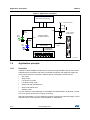
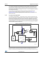
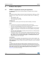
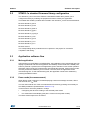
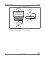
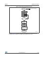
AN3413
Application note
STM32L1x current consumption measurement
and touch sensing demonstration firmware
Introduction
This application note provides an overview of the demonstration firmware delivered with the
STM32L-DISCOVERY and 32L152CDISCOVERY evaluation boards. It allows you to
explore the rich set of power saving modes available in the STM32L1x microcontroller and
use the STM32L1xx DISCOVERY embedded IDD measurement circuit to demonstrate the
real capabilities of the Ultra low power microcontroller STM32L1x.
The demonstration application does not require any additional hardware. Once the
STM32L1xx DISCOVERY is powered-up through a USB cable connected to the host PC,
the application is ready to display the STM32L1x power consumption of each low-power
mode selected by the user.
In addition the demonstration firmware allows you to explore the touch sensing capabilities
of the STM32L1x microcontroller demonstrated by sensing the linear touch sensor or the set
of four touchkeys.
Reference documents
The current consumption measurement and touch sensing demonstration firmware is
included in the STSW-STM32072 STM32L1 discovery firmware package available from
http://www.st.com.
• STM32L1 discovery kits: STM32L-DISCOVERY and 32L152CDISCOVERY (UM1079)
• Getting started with software development toolchains for the STM32L-DISCOVERY and
32L152CDISCOVERY board (UM1451)
The above documents are available at http://www.st.com.
Table 1 lists the microcontrollers, evaluation tools and software concerned by this
application note.
Table 1. Applicable products, evaluation tools and software
Type
June 2013
Part numbers
Microcontrollers
STM32L1 Series
Evaluation tools
STM32L-DISCOVERY, 32L152CDISCOVERY
MCU software
STSW-STM32072
DocID018933 Rev 2
1/18
www.st.com
Contents
AN3413
Contents
1
Application description . . . . . . . . . . . . . . . . . . . . . . . . . . . . . . . . . . . . . . 3
1.1
Used hardware components . . . . . . . . . . . . . . . . . . . . . . . . . . . . . . . . . . . 3
1.2
STM32L1xx DISCOVERY hardware settings . . . . . . . . . . . . . . . . . . . . . . . 3
1.3
Application schematics . . . . . . . . . . . . . . . . . . . . . . . . . . . . . . . . . . . . . . . . 3
1.4
Application principle . . . . . . . . . . . . . . . . . . . . . . . . . . . . . . . . . . . . . . . . . . 4
1.5
1.6
2
1.4.1
Overview . . . . . . . . . . . . . . . . . . . . . . . . . . . . . . . . . . . . . . . . . . . . . . . . . 4
1.4.2
IDD measurement principle . . . . . . . . . . . . . . . . . . . . . . . . . . . . . . . . . . . 5
Getting started with the application . . . . . . . . . . . . . . . . . . . . . . . . . . . . . . 6
1.5.1
Demo mode - Touch sensing demonstration and IDD measurement . . . . 6
1.5.2
Bias current record . . . . . . . . . . . . . . . . . . . . . . . . . . . . . . . . . . . . . . . . . 8
1.5.3
Manufacturing test . . . . . . . . . . . . . . . . . . . . . . . . . . . . . . . . . . . . . . . . . . 8
Low power modes . . . . . . . . . . . . . . . . . . . . . . . . . . . . . . . . . . . . . . . . . . . 9
Software description . . . . . . . . . . . . . . . . . . . . . . . . . . . . . . . . . . . . . . . . 10
2.1
STM32L1x peripherals used by the application . . . . . . . . . . . . . . . . . . . . 10
2.2
STM32L1x standard firmware library configuration . . . . . . . . . . . . . . . . . .11
2.3
Application software flow . . . . . . . . . . . . . . . . . . . . . . . . . . . . . . . . . . . . . .11
2.3.1
Main application . . . . . . . . . . . . . . . . . . . . . . . . . . . . . . . . . . . . . . . . . . . 11
2.3.2
Demo mode (IDD measurement) . . . . . . . . . . . . . . . . . . . . . . . . . . . . . . 11
3
Conclusion . . . . . . . . . . . . . . . . . . . . . . . . . . . . . . . . . . . . . . . . . . . . . . . . 16
4
Revision history . . . . . . . . . . . . . . . . . . . . . . . . . . . . . . . . . . . . . . . . . . . 17
2/18
DocID018933 Rev 2
AN3413
1
Application description
Application description
STM32L1xx DISCOVERY stands either for STM32L-DISCOVERY or 32L152CDISCOVERY
evaluation kit throughout the document.
1.1
Used hardware components
This application example uses the hardware components available on STM32L1xx
DISCOVERY; on-board LEDs (green LD3 and blue LD4), the 6-digit/4-bar LCD glass
display, the user push-button and touch sense slider. No additional components are
required.
1.2
STM32L1xx DISCOVERY hardware settings
The IDD jumper JP1 must be placed in position ON for standard operation (except for bias
current record operation, see Section 1.5.2).
Both jumpers on CN3 must be fitted to allow communication of STM32L15x with ST-Link
debugging tool thru SWD interface.
Note:
All solder bridges must be in the default state as described in UM1079.
1.3
Application schematics
Figure 1 shows the simplified application electrical schematics.
DocID018933 Rev 2
3/18
17
Application description
AN3413
Figure 1. Application schematics
IDD measurement circuitry
VDD
User push-button
C25
PA4
PA0
PC13
100 nF
PB7
PA0
R39
330 Ȱ
R38
10 k Ȱ
LD3
Green
PB6
Touch sensing
linear sensor
STM32L152RBT6
or STM32L152RCT6
R40
660 Ȱ
LD4
Blue
PB0..1, PC4..5,
PA6..7
LCD controller
LCDCOM[3:0]
LCDSEG[23:0]
3
2
1
0
BAR
LCD
1.4
Application principle
1.4.1
Overview
MS19810V2
STM32L1xx DISCOVERY includes specific analog and logic hardware that is connected to
STM32L152 microcontroller and which is intended to measure and display the supply IDD
current when the device is placed in different power consumption modes such as:
•
Run mode
•
Sleep mode
•
Low power run mode
•
Low power sleep mode
•
Stop mode with operating RTC
•
Stop mode without RTC
•
Standby mode
The user reads the value displayed on the STM32L1xx DISCOVERY’s LCD panel, to know
how much power the device is currently consuming.
With this demonstration, you can obtain an overview of low power modes and supply current
requirements for each low power mode available on STM32L152.
4/18
DocID018933 Rev 2
AN3413
Application description
The firmware associated with this application note also provides a demonstration of the
touch sensing functionality available on STM32L1xx DISCOVERY. The touch sensing
electrodes can be configured either as a linear touch sensor to perform linear sensing of
finger position displayed as a percentage on the LCD, or, it can be configured as a group of
four independent touchkeys.
It also includes a manufacturing test mode for performing a quick diagnosis of the
STM32L1xx DISCOVERY related to this application example. See Section 1.5.3:
Manufacturing test for details regarding the test activation and for an explanation of the
different test modes.
IDD measurement principle
The STM32L1xx DISCOVERY IDD measurement circuitry consists of measuring the high
side shunt voltage value V at the terminals of a high precision serial resistor (1%) inserted
between the +3V3 power supply and the VDD pin of the MCU. Depending on the device
power modes, the application uses R or [2000 + 2] x R as the equivalent resistor value by
closing or opening K1. In Run mode, the current is in the range of mA, K1 is closed, and the
equivalent resistor is R. In low power modes, the current is in the µA range, K1 is opened,
and the equivalent resistance is 2002 x R.
Figure 2. IDD measurement equivalent circuitry
+3V3
IDD
Gain = 50
1%
2R
V
K1
2k
A
S
1%
1.4.2
C
VDD
Q14 Q13
Counter
EN
PA4
IDD meas
+3 V3
STM32L15x
PC13
PA0
LP wake-up
K2
GND
MS19811V1
This resistor is connected between the differential inputs of a high-side current sense
operational amplifier (A) with a fixed gain that amplifies the voltage (V) present on the
resistors. A sample and hold stage is placed at the operational amplifier output and is then
DocID018933 Rev 2
5/18
17
Application description
AN3413
connected to an analog input of the MCU (PA4 IDD Measurement) that finally converts the
resulting voltage, image of the consumption current.
In low power modes only, a counter enabled by STM32L15x (PC13 pin) manages the
measurement timing while the microcontroller is idle. The microcontroller is woken-up after
a 150 ms delay when the rising edge is triggered on a wake-up pin (PA0) controlled by the
K2 switch.
While the microcontroller is in one of the power saving modes, a capacitor (C) is charged
with the voltage amplified by the operational amplifier. The microcontroller can later sample
(during its wake-up phase - 50 ms) the value of capacitor voltage proportional to the current
consumption of MCU in low power mode. Switch S is opened at device start-up in order to
keep the charge collected in capacitor (C) intact while the microcontroller is in low power
mode.
The current measurement precision is enhanced by taking into account the current bias of
high-side current operational amplifier. When JP1 is placed in OFF position (IDD
measurement circuitry disabled), a special test invoked by the user at device start-up
measures this current value and stores it in the non-volatile memory. Once this value is
stored in the device, it is deducted from the next IDD measurement to compensate errors
due to I bias current (see Section 1.5.2: Bias current record).
For additional information related to the IDD measurement feature, please refer to
section 4.7, Built-in IDD measurement circuit of the STM32L1 discovery kits: STM32LDISCOVERY and 32L152CDISCOVERY user manual (UM1079).
1.5
Getting started with the application
This STM32L1xx DISCOVERY example application has 3 application modes that can be
run:
•
Demo mode (touch sensor, IDD measurement)
•
Bias current record
•
Manufacturing test
Demo mode is available at application power-up while the two others are invoked by the
user using a specific procedure that is described in detail later in this chapter. However, for
best performance, it is recommended to measure and record the bias current before starting
evaluation of low power mode IDD current.
1.5.1
Demo mode - Touch sensing demonstration and IDD measurement
Once the application is powered-up via the USB cable (or by external power supply), it starts
displaying a welcome message and then, after a few seconds, the value of the VDD voltage
applied to the STM32L1x device.
LD3 (green LED) and LD4 (blue LED) blink alternately. As soon as IDD consumption values
are displayed, both LEDs are turned off.
The User push-button allows you to change the functions as described in the state diagram
in Figure 3.
The first step is a demonstration of the linear touch sensor function followed by a touchkey
demo activated by pressing the user button.
6/18
DocID018933 Rev 2
AN3413
Application description
When the used push button is pressed again, the power consumption measurement
functions are launched. These functions consist of configuring the device for each low
power consumption mode and then measuring and displaying the result on the LCD panel.
Figure 3. Function Change state diagram
START
reset
VDD
meas
TOUCH
LINEAR
SENSOR
STANDBY
IDD
User button
pressed
STOP
IDD
TOUCHKEYS
LPRUN
LPSLEEP
IDD
RUN
SLEEP
IDD
MS19812V1
BAR0 to BAR3 are used by the application to indicate ongoing measurements as shown in
Table 1.
In order to save power during the IDD measurement in Stop mode without LCD, the LCD is
switched off. Once the measurement is performed the LCD is switched on to display the
power consumption value.
Table 1. Bars and LCD display linked to functions
Function
Bars
VDD / Linear sensor / Touch buttons
Run mode / Sleep mode
DocID018933 Rev 2
7/18
17
Application description
AN3413
Table 1. Bars and LCD display linked to functions (continued)
Function
Bars
Low power run / Low power sleep
STOP / STOP without LCD
STANDBY mode
1.5.2
Bias current record
This operation consists of storing the bias current value of operational amplifier A (see
Figure 2) in the data memory. The bias current value is taken into account for low power
measurements in order to minimize measurement errors. Once recorded, this value is kept
in non-volatile memory for later use. It is recommended to perform this operation when you
start your evaluation in order to obtain the best precision.
This mode is only accessible at application power-up by executing the following steps in the
order below:
1.
Switch OFF STM32L1xx DISCOVERY
2.
Place JP1 in OFF position (IDD measurement disabled)
3.
Keep USER push-button pressed while powering ON the STM32L1xx DISCOVERY
4.
At power on, a scrolling message “Bias Current” is displayed
5.
Release the USER push-button; the bias current value is displayed and immediately
stored in non-volatile memory
Once this operation completed, replace JP1 in ON position so that the measurement
circuitry is connected again to the STM32L152 (IDD measurement enabled).
1.5.3
Manufacturing test
You can access this mode while Demo mode is running, by pressing the USER push-button
for more than 3 seconds and by releasing it. This allows you to verify that the hardware
modules needed by the STM32L1xx DISCOVERY for this example are working properly.
In this mode, application checks the LSE oscillator (Low Speed External), VDD voltage
value, IDD RUN, OA bias and LP (low power) IDD currents. The currents are tested for lower
and upper limits. For each test function, the application displays “OK” and the measured
values when available. If all checks are successfully completed, then the message “TEST
OK” is continuously displayed. If one of the tests fails, then the application alerts the user by
continuously displaying the test name followed by “NO OK”.
To exit this manufacturing test, press the RESET button.
Note:
8/18
Generally, if the manufacturing test is not successful, first check that JP1 is placed in the ON
position and that all solder bridges are in default position. If errors are found in the Low
DocID018933 Rev 2
AN3413
Application description
power and Halt modes IDD measurements, the bias current record operation should be
performed again.
1.6
Low power modes
The low power modes used in this application are listed below. The microcontroller can be
woken up from any power saving mode by an external wake-up event generated by counter
U3.
•
Sleep mode: The CPU is stopped, the peripherals kept running. The system is clocked
by the MSI oscillator at a frequency of 4 MHz.
•
Low power run mode: The CPU and some of the peripherals are running. During Low
power run mode, the code is executed from RAM and the CPU is clocked at a
frequency of 32 kHz by the MSI oscillator. Flash and data EEPROM are stopped and
the voltage regulator is configured in Ultra low power mode.
•
Low power sleep mode: The CPU is stopped. The system clock frequency is reduced
to 32 kHz. Flash and Data EEPROM are in power down mode and the voltage
regulator is configured in Ultra low power mode.
•
Stop mode: The Core is in Deepsleep mode, Flash, Data EEPROM and all clocks
except LSE are in power down mode. All peripherals except the LCD are disabled. The
voltage regulator is in low power mode.
•
Stop mode without LCD: This is the same as Stop mode except that the LCD
controller is also disabled in this case.
•
Standby mode: This is the deepest low power mode. The voltage regulator is
disabled. Core, peripherals, RAM, Flash and Data EEPROM are powered off. Power is
maintained for the RTC registers, backup registers and standby circuitry. Device wakeup is done by an external wake-up event, generating a system reset.
For further information, please refer to STM32L15x reference manual (RM0038) where you
can find more details about all the available configurations for each STM32L15x low power
mode.
DocID018933 Rev 2
9/18
17
Software description
AN3413
2
Software description
2.1
STM32L1x peripherals used by the application
This application example uses the following STM32L1x peripherals with the settings
described below:
ADC
ADC performs analog-to-digital conversions of the internal reference voltage (VDD voltage
display) and of the voltage coming from the operational amplifier that is the image of IDD
current.
•
ADC resolution: 12-bit
•
ADC conversion mode: single
•
ADC sampling time: 192 cycles
SYSTICK Timer
The Systick timer is used to generate the delay needed for display or wait loops.
GPIOs
Port C and Port E are connected to the USER push-button and the LEDs.
•
PB1 set as an input floating pin with interrupt connected to the USER push-button
•
PB7 (green LD3) and PB6 (blue LD4) set as an output push-pull
•
PA0 set as a wake-up pin configured either as an input floating pin with interrupt with
detection on rising edge or as an alternate function AFIO0 (WKUP1) during Standby
mode.
•
PA6, PA7, PC4, PC5, PB0, PB1 are used for linear touch sensor or touchkeys during
the touch sensor demonstration.
•
During the low power modes, I/Os are placed in analog input mode to reduce power
consumption except for a few pins related to the hardware interface (PB7 - green LD3
PB6 - blue LD4, PA4 - IDD measurement pin, PA0 - LP WakeUp pin and PC13 - IDD
timer enable). This means that all Schmitt triggers on unused standard I/O pins are
disabled to reduce power consumption.
LCD controller
The different functions available in the firmware library for LCD are used to initialize, clear,
display strings and scrolling messages needed in the application code. For some low power
mode measurements, the LCD controller is turned OFF to minimize the current consumption
of the STM32L152.
Clock
The MSI (the multi speed internal oscillator) oscillator is selected as clock source. The
application manages the peripheral clocks depending on the selected power saving mode.
When the device enters low power run mode, MSI is switched to range 0 until the device is
woken-up by an external event. When exiting Low power run mode, the MCU switches the
HSI oscillator back ON. LSE is switched ON during Manufacturing test mode (see
Section 1.5.3) to check its functionality.
10/18
DocID018933 Rev 2
AN3413
2.2
Software description
STM32L1x standard firmware library configuration
The stm32l1xx_conf.h file of the STM32L1x standard firmware library allows you to
configure the library by enabling the peripheral functions used by the application.
The header files of library modules are included in the stm32l1xx_conf.h file as listed bellow.
#include stm32l1xx_adc.h
#include stm32l1xx_exti.h
#include stm32l1xx_flash.h
#include stm32l1xx_gpio.h
#include stm32l1xx_syscfg.h
#include stm32l1xx_lcd.h
#include stm32l1xx_pwr.h
#include stm32l1xx_rcc.h
#include stm32l1xx_rtc.h
#include "misc.h"
The corresponding library modules has to be present in the project for successful
compilation and linking.
2.3
Application software flow
2.3.1
Main application
After powering up the STM32L1xx DISCOVERY, the initialization of the peripherals and LCD
display is performed and then the application immediately checks whether the USER pushbutton is pressed. If pressed, then the application goes to the Bias current record operation.
Otherwise, Demo mode (IDD measurement) is automatically selected. If during Demo mode,
the user presses the USER key for more than 3 seconds, then the application enters
manufacturing test. To exit manufacturing test, the application needs to be restarted by
pressing the RESET button.
2.3.2
Demo mode (IDD measurement)
When Demo mode is launched, it starts displaying a welcome message and then, after a
few seconds, the VDD value.
The user then selects one of the IDD measurement functions by pressing successively on
the USER pushbutton (as described in Section 1.5.1).
These functions are mainly divided in 2 steps:
•
Configuring the device according to the selected power mode
•
IDD measurement and display (this part is common for all power modes)
The Demo mode sequence is as follows:
DocID018933 Rev 2
11/18
17
Software description
AN3413
Figure 4. Demo mode sequence
Demo mode
(IDD measurement)
START
Run mode
Sleep Mode
Stop - RTC ON
Stop - RTC OFF
LP Run
LP Sleep
Standby
Configuration
steps
IDD measurement &
display
END
MS19814V1
Low power modes configuration
For IDD measurement in Run mode, there is no particular setup needed other that
performed during the STM32L1x power on initialization. For this function, the application
goes directly to IDD measurement and display routine.
The configuration of device for Low power run, Sleep, Stop with and without RTC is detailed
in Figure 5. Please, see RM0038 for more details about low power modes available on
STM32L1x.
12/18
DocID018933 Rev 2
AN3413
Software description
Figure 5. Low power mode flowchart
START
LCD disable
LCD clock OFF
RTC clock source None *
RTC clock OFF *
Regulator in Ultra low power mode **)
GPIO Low power config
Disable external counter U3
Disable fast wakeup
Configure LP clock
Configure interrupt/event
Switch OFF flash memory ***)
Switch OFF regulator
WFE set to external event from PA0
Enable external counter U3
Wait For Event or
Wait For Interrupt
Event or
Interrupt
occurred?
NO
YES
Clear interrupt / event
Switch ON regulator
Reconfigure clock
*) except Stop with RTC
**) except Sleep mode
***) only for LP RUN, Sleep and LP Sleep
END
MS19816V1
In Standby mode, the device is in its deepest energy saving state. The device enters the
Cortex-M3 deepsleep mode and the voltage regulator is disabled. All oscillators are
switched off. SRAM and register contents are lost with the exception of the RTC registers,
RTC backup registers and Standby circuitry. The device is woken up from this mode by an
external wakeup event generated by the U3 counter invoking a system reset.
DocID018933 Rev 2
13/18
17
Software description
AN3413
Figure 6. Standby mode flowchart
START
Reset
LCD disabled
RTC disabled
Disable clock sources
System clock to MSI 32 kHz
Configure wake-up pin
Regulator Ultra low power mode
GPIO Low power config
Enable external counter U3
Standby
flag?
Measure Standby current
Enter Standby mode
Continue
wake-up
event?
NO
YES
Reset
MS19817V1
IDD measurement and display
The following flowchart describes the IDD measurement process.
14/18
DocID018933 Rev 2
AN3413
Software description
Figure 7. Measurement and display flowchart
START
IDD measurement & display
Disable interrupts
ADC init
Get conversion
4 times?
NO
YES
Disable external
counter U3
Disable ADC
peripheral
Perform average
display on LCD
measured current
END
MS19815V1
As shown in Figure 7, the ADC conversion is performed 4 times in succession and an
average value is computed. The average value is displayed on the LCD.
DocID018933 Rev 2
15/18
17
Conclusion
3
AN3413
Conclusion
This application note shows the demonstration firmware delivered with your
STM32L-DISCOVERY or 32L152CDISCOVERY kit. This example allows you to evaluate
the touch sensing capability of STM32L1xx microcontrollers and demonstrate its Ultra low
power features by providing the measured current consumption values in selected low
power modes directly on the LCD.
The low-cost STM32L-DISCOVERY or 32L152CDISCOVERY kit with the firmware example
associated with this application note provides a starting point for your own evaluation of
current consumption of application specific tasks running on the Ultra low power STM32L1x
microcontroller.
16/18
DocID018933 Rev 2
AN3413
4
Revision history
Revision history
Table 2. Document revision history
Date
Revision
04-Jul-2011
1
Initial release
2
Added 32L152CDISCOVERY.
Removed PM0062 and added UM1451 in Reference documents.
Updated Clock section.
27-Jun-2013
Changes
DocID018933 Rev 2
17/18
17
AN3413
Please Read Carefully:
Information in this document is provided solely in connection with ST products. STMicroelectronics NV and its subsidiaries (“ST”) reserve the
right to make changes, corrections, modifications or improvements, to this document, and the products and services described herein at any
time, without notice.
All ST products are sold pursuant to ST’s terms and conditions of sale.
Purchasers are solely responsible for the choice, selection and use of the ST products and services described herein, and ST assumes no
liability whatsoever relating to the choice, selection or use of the ST products and services described herein.
No license, express or implied, by estoppel or otherwise, to any intellectual property rights is granted under this document. If any part of this
document refers to any third party products or services it shall not be deemed a license grant by ST for the use of such third party products
or services, or any intellectual property contained therein or considered as a warranty covering the use in any manner whatsoever of such
third party products or services or any intellectual property contained therein.
UNLESS OTHERWISE SET FORTH IN ST’S TERMS AND CONDITIONS OF SALE ST DISCLAIMS ANY EXPRESS OR IMPLIED
WARRANTY WITH RESPECT TO THE USE AND/OR SALE OF ST PRODUCTS INCLUDING WITHOUT LIMITATION IMPLIED
WARRANTIES OF MERCHANTABILITY, FITNESS FOR A PARTICULAR PURPOSE (AND THEIR EQUIVALENTS UNDER THE LAWS
OF ANY JURISDICTION), OR INFRINGEMENT OF ANY PATENT, COPYRIGHT OR OTHER INTELLECTUAL PROPERTY RIGHT.
ST PRODUCTS ARE NOT AUTHORIZED FOR USE IN WEAPONS. NOR ARE ST PRODUCTS DESIGNED OR AUTHORIZED FOR USE
IN: (A) SAFETY CRITICAL APPLICATIONS SUCH AS LIFE SUPPORTING, ACTIVE IMPLANTED DEVICES OR SYSTEMS WITH
PRODUCT FUNCTIONAL SAFETY REQUIREMENTS; (B) AERONAUTIC APPLICATIONS; (C) AUTOMOTIVE APPLICATIONS OR
ENVIRONMENTS, AND/OR (D) AEROSPACE APPLICATIONS OR ENVIRONMENTS. WHERE ST PRODUCTS ARE NOT DESIGNED
FOR SUCH USE, THE PURCHASER SHALL USE PRODUCTS AT PURCHASER’S SOLE RISK, EVEN IF ST HAS BEEN INFORMED IN
WRITING OF SUCH USAGE, UNLESS A PRODUCT IS EXPRESSLY DESIGNATED BY ST AS BEING INTENDED FOR “AUTOMOTIVE,
AUTOMOTIVE SAFETY OR MEDICAL” INDUSTRY DOMAINS ACCORDING TO ST PRODUCT DESIGN SPECIFICATIONS.
PRODUCTS FORMALLY ESCC, QML OR JAN QUALIFIED ARE DEEMED SUITABLE FOR USE IN AEROSPACE BY THE
CORRESPONDING GOVERNMENTAL AGENCY.
Resale of ST products with provisions different from the statements and/or technical features set forth in this document shall immediately void
any warranty granted by ST for the ST product or service described herein and shall not create or extend in any manner whatsoever, any
liability of ST.
ST and the ST logo are trademarks or registered trademarks of ST in various countries.
Information in this document supersedes and replaces all information previously supplied.
The ST logo is a registered trademark of STMicroelectronics. All other names are the property of their respective owners.
© 2013 STMicroelectronics - All rights reserved
STMicroelectronics group of companies
Australia - Belgium - Brazil - Canada - China - Czech Republic - Finland - France - Germany - Hong Kong - India - Israel - Italy - Japan Malaysia - Malta - Morocco - Philippines - Singapore - Spain - Sweden - Switzerland - United Kingdom - United States of America
www.st.com
18/18
DocID018933 Rev 2