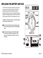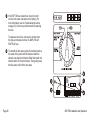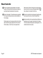
1
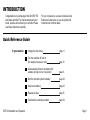
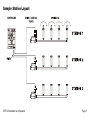
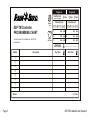
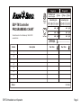
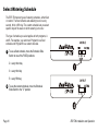
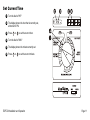
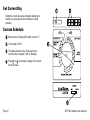
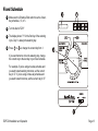
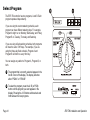
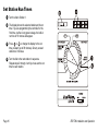
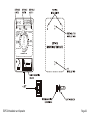
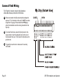
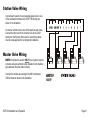
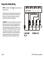
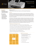
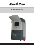
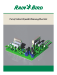
Installation,
Programming,
& Operation
ESP-4TM
ESP-6TM
ESP-8TM
Contents
INTRODUCTION
Quick Reference Guide
Controller Stations
Sample Station Layout
Controls and Switches
PROGRAMMING THE CONTROLLER
Default Program
Programming Checklist
Fill Out Program Schedule Sheet
Select Watering Schedule
Set Current Time
Set Current Day
Custom Schedule
Fixed Schedule
Select Program
Set Station Watering Days
Set Station Run Times
Set Watering Start Times
1
1
2
3
4
5
5
6
7
10
11
12
12
13
14
15
16
17
OPERATING THE CONTROLLER
Turn Controller On and Off
Adjust Water Budget Percent
Use Manual Start / Advance
Run Test Program
19
19
21
23
24
REPLACING THE BATTERY AND FUSE
25
INSTALLING THE CONTROLLER
Select Location
Mount Controller
Connect Field Wiring
Station Valve Wiring
Master Valve Wiring
Pump Start Relay Wiring
Install Battery
Install Transformer
Install Wiring Skirt
27
27
28
30
31
31
32
33
34
35
TROUBLESHOOTING
36
HAVE A QUESTION, PROBLEM, OR COMMENT?
Our toll-free Technical Services phone number is 1-800-247-3782
INTRODUCTION
Congratulations on purchasing a Rain Bird ESP-TM
solid state controller. This manual describes how to
install, operate, and maintain your controller. Please
read these instructions carefully.
For your convenience, we have included a Quick
Reference Guide below, so you can quickly find
instructions for common tasks.
Quick Reference Guide
If you want to:
ESP-TM Installation and Operation
Change the time of day
page 11
Turn the controller off and on
(for example, because of rain)
page 19
Adjust watering times for all stations (for
example, during a hot or cool period)
page 21
Start the sprinkler system manually
page 23
Install a new battery
page 25
Replace the fuse
page 25
Troubleshoot a controller problem
page 36
Page 1
Controller Stations
The controller has several stations as shown in the
illustration on the following page. Each station is
connected to a remote control sprinkler valve.
The valve opens when it receives a signal from the
controller, and the sprinklers connected to the valve
turn on. When these sprinklers have run for their
allotted time, the controller shuts off the valve and
opens the next valve in sequence.
Page 2
For example, the illustration shows that station 1 is
currently watering.
When station 1 is finished, the controller will shut it
off and start station 2.
In the same way, station 3 will begin watering when
station 2 is finished.
ESP-TM Installation and Operation
Sample Station Layout
ESP-TM Installation and Operation
Page 3
Controls and switches
The illustration shows the programming controls on the face
of the ESP-TM. These controls include:
1
LCD Display - during normal operation, displays the
time of day; during programming, shows the results of
your commands; during watering, shows the station that
is running and the minutes remaining in its run time.
2
Arrow ON-OFF Buttons - used to set times and days,
and to make program changes.
3
A / B Program Button - used to select watering
program A or B. (On some ESP models, this button is
labeled PGM.)
4
Manual Start / Advance Button - used to start the
irrigation program manually or to manually advance
watering from one station to the next.
5
Programming Dial - used to turn controller off and on,
and for programming.
6
Schedule Slide Switch - used to select one of the
fixed-interval watering schedules or a custom watering
schedule.
Page 4
ESP-TM Installation and Operation
PROGRAMMING THE CONTROLLER
Your ESP-TM controller is an electronic clock that controls when
your sprinkler system turns on, and how long the sprinklers run.
Monday, Wednesday, Friday), or the watering interval
(for example, every third day).
Programming is the process of telling the controller exactly when
and how long you want to water. The controller opens and closes
the remote control valves according to the program you set.
Start time - the time of day that the program begins; this
is the time that the first station in the program begins
watering; all other stations then follow in sequence.
Each program contains: Watering days - the specific
days of the week on which watering takes place (for
example,
Run time - the number of minutes that each station runs.
Default Program
The ESP-TM series controllers have a backup, or default,
program that takes over if your program is lost because of an
extended power outage.
If the Schedule Slide Switch is set to one of the fixed
intervals, the default program will run every two, three,
or five days, depending on where the switch is set.
When the default program is running, all stations revert to
Program A, with 10 minutes of run time per station. The default
starting time is 8:00 AM.
The Program A default settings will be in operation until you
enter your desired settings for Program A. As you enter your
settings in Program A, the default settings are pushed into
reserve status as a backup program. If you are using only
one of the two programs, make sure you use Program A.
The default program will water every day if the Schedule Slide
Switch is set to "Custom."
ESP-TM Installation and Operation
Page 5
Programming Checklist
To program the ESP-TM controller for the first time, we
recommend that you complete the following steps in order:
Fill out Program Schedule Sheet
Page 6
page 7
Select watering schedule
page 10
Set the current time
page 11
Set the current day
page 12
Select the program (A or B)
page 14
Set station watering days (custom
schedule only)
page 15
Set station run times
page 16
Set watering start times
page 17
Set controller to automatic operation
page 19
ESP-TM Installation and Operation
Fill Out Programming Chart
Before you begin programming, fill out the ESP-TM Controller Programming Chart and keep it for reference. A sample
Programming Chart is shown in this illustration. Several blank Charts are provided for your use on the following pages.
1
2
3
4
5
Enter a brief description of each station on
the controller.
4
In the Program A column, circle the Watering
Days schedule. Either choose one of the "Fixed
Day Cycle" intervals, or choose the desired
watering days in the "Custom Day Cycle" row.
Enter the starting time(s) for Program A. You
may have up to three separate start times
for each program.
Enter the run time for each station assigned
to Program A. Enter "0" for stations that are
not used in Program A.
Repeat steps 2 - 4 for Program B. If you are
using a fixed schedule, Program B will have
the same watering days as Program A.
ESP-TM Installation and Operation
3
2
5
Program A
Fixed Day Cycle
(applies to all programs)
1
ESP-TM Controller
PROGRAMMING CHART
Technical Services for U.S. and Canada only: 1-800-247-3782
www.rainbird.com
Watering
Days
Program
Start Times
Custom Day Cycle
Description
3 Days
5 Days
Custom Day Cycle
M T W T F S S
M T W T F S S
1
am
pm
1
am
pm
2
am
pm
2
am
pm
am
pm
3
am
pm
3
Water Budget
(applies to all programs)
Station
Program B
2 Days
Run Time
........................................
Run Time
1
2
3
4
5
6
7
8
Notes:
P/N 632989A
Page 7
Program A
Fixed Day Cycle
(applies to all programs)
ESP-TM Controller
PROGRAMMING CHART
Technical Services for U.S. and Canada only: 1-800-247-3782
www.rainbird.com
Watering
Days
Program
Start Times
Description
3 Days
5 Days
Custom Day Cycle
Custom Day Cycle
M T W T F S S
M T W T F S S
1
am
pm
1
am
pm
2
am
pm
2
am
pm
3
am
pm
3
am
pm
Water Budget
(applies to all programs)
Station
Program B
2 Days
Run Time
........................................
Run Time
1
2
3
4
5
6
7
8
Notes:
Page 8
P/N 632989A
ESP-TM Installation and Operation
Program A
Fixed Day Cycle
(applies to all programs)
ESP-TM Controller
PROGRAMMING CHART
Technical Services for U.S. and Canada only: 1-800-247-3782
www.rainbird.com
Watering
Days
Program
Start Times
Description
3 Days
5 Days
Custom Day Cycle
Custom Day Cycle
M T W T F S S
M T W T F S S
1
am
pm
1
am
pm
2
am
pm
2
am
pm
3
am
pm
3
am
pm
Water Budget
(applies to all programs)
Station
Program B
2 Days
Run Time
........................................
Run Time
1
2
3
4
5
6
7
8
Notes:
ESP-TM Installation and Operation
P/N 632989A
Page 9
Select Watering Schedule
The ESP-TM has two types of watering schedules, either fixed
or custom. The fixed schedule sets watering to occur every
second, third, or fifth day. The custom schedule lets you select
specific days of the week on which watering is to occur.
The type of schedule you select applies to both programs, A
and B. For example, you cannot set Program A to a fixed
schedule and Program B to a custom schedule.
1
To use a fixed schedule, move the Schedule Slide
Switch to one of the FIXED positions:
2 = every other day
3 = every third day
5 = every fifth day
2
To use the custom schedule, move the Schedule
Slide Switch to the "C" position.
Page 10
ESP-TM Installation and Operation
Set Current Time
1
Turn the dial to "HR."
2
The display shows the hour that is currently set,
either AM or PM.
3
Press
4
Turn the dial to "MIN."
5
The display shows the minute currently set.
6
Press
or
or
to set the current hour.
to set the current minute.
ESP-TM Installation and Operation
Page 11
Set Current Day
Setting the current day varies somewhat depending on
whether you are using a custom schedule or a fixed
schedule.
Custom Schedule
1
Make sure the Schedule Slide switch is set to "C."
2
Turn the dial to "DAY."
3
The display shows the day of the week that is
currently set (for example, "MO" for Monday).
4
Press
or
to change the display to the current
day of the week.
Page 12
ESP-TM Installation and Operation
Fixed Schedule
1
Make sure the Schedule Slide switch is set to a fixedday schedule: 2, 3, or 5.
2
Turn the dial to "DAY."
3
The display shows "1" for the first day of the watering
cycle. Day 1 is always the watering day.
4
Press
or
to change the current day from 1.
If you want tomorrow to be the watering day, change
the current day to the last day in your fixed schedule.
For example, if you're using a two-day schedule and
you want to start watering tomorrow, set the current
day to "2." If you're using a three-day schedule and
you want to start tomorrow, set the current day to "3."
ESP-TM Installation and Operation
Page 13
Select Program
The ESP-TM controller has two programs, A and B. Each
program operates independently.
If you are using the custom watering schedule, each
program can have different watering days. For example,
Program A might run on Monday, Wednesday, and Friday;
Program B on Tuesday, Thursday, and Saturday.
If you are using a fixed watering schedule, both programs
will have the same "ON" days. For example, if you are
using the three-day fixed schedule, Program A and
Program B will both run every third day.
You can assign any station to Program A, Program B, or
both.
1
The program that is currently selected appears in the
far left corner of the display. The display will show
either "PGM A" or "PGM B."
2
To select the program, press the A / B (or PGM)
button until the program you want appears in the
display. Pressing the A / B button switches back and
forth between the two programs.
Page 14
ESP-TM Installation and Operation
Set Station Watering Days
NOTE: You must set station watering days ONLY if you
are using the CUSTOM Schedule. If you are using one of
the FIXED schedules, skip to page 16.
1
Turn the dial to "MON."
2
The display shows the day of the week (for example,
"MO" for Monday) and either "ON" or "OFF." ON
means the selected day is a watering day. OFF
means watering doesn't take place on the selected
day.
3
Press the ON or OFF button to set the selected day
of the week on or off.
4
Turn the dial to the next day of the week. Repeat
steps 2 and 3 until you have set each day of the
week either on or off.
ESP-TM Installation and Operation
Page 15
Set Station Run Times
1
Turn the dial to Station 1.
2
The display shows the selected station and its run
time. If you are programming the controller for the
first time, or after a long power outage, the built-in
run time of 10 minutes will appear.
3
Press
or
to change the display to the run
time you want (up to 99 minutes). Set any unused
stations to 0 minutes.
4
Turn the dial to the next station in sequence.
Repeat steps 2 through 4 until you have set the run
time for each station.
Page 16
ESP-TM Installation and Operation
Set Watering Start Times
Each program on the ESP-TM can have up to three
watering start times, which tell the controller when to
begin the watering program. The start time applies to all
watering days for that program.
If you want to water more than once a day, you can set
the second and third watering start times. For example, if
you are growing new lawn seed, you might want to water
several times a day. To do so, you could set a program to
run at 6:00 AM, 11:00 AM, and 4:00 PM.
1
Make sure the program you want appears in the
display. Either "PGM A" or "PGM B" will appear.
To switch to the other program, press the A / B
(or PGM) button.
2
Turn the dial to 1 in the "Watering Start Times"
section.
3
The display shows the start time currently set for
this program section.
ESP-TM Installation and Operation
Page 17
4
Press
or
to change the start time. The time setting
moves forward or backward in 15-minute increments.
5
To eliminate a start time, press
or
until the blank
setting between 11:45 PM and 12:15 AM appears.
If you want to set additional start times for this program, move
the dial to 2 or 3 in the "Watering Start Times" section. Then
repeat steps 3 and 4.
If you are following the programming checklist on page 6, you
have now completed all programming steps for Program A.
At this point, you may:
Enter Program B by following the steps that
begin on page 14, or
Set the controller to automatic operation, as
described on page 19.
Page 18
ESP-TM Installation and Operation
OPERATING THE CONTROLLER
Turn Controller On and Off
1
To set the controller to automatic operation, turn the
dial to AUTO. The display will show the current day
and time until the next scheduled automatic start.
When a program is running, the display will show the
station currently turned on and the minutes remaining
on its run time. When the entire program is complete,
the display will change back to the current day and
time.
If you forget to turn the dial to AUTO, the controller will
eventually set itself to automatic operation. The only
setting that prevents automatic operation is OFF (see
step 2).
ESP-TM Installation and Operation
Page 19
2
To turn the controller off and prevent all watering, set
the dial to OFF. The display will show the current day
and time. In addition, the right-hand minute digit will
blink to show that the controller has been turned off.
The OFF setting can be used during rainy weather,
seasonal shutdown, or system maintenance.
Page 20
ESP-TM Installation and Operation
Adjust Water Budget Percent
The Water Budget feature on the ESP-TM lets you
increase or decrease the run times of all stations by a
selected percentage. You may adjust the run times as low
as 10 percent and as high as 200 percent. Adjustments
must be made in increments of 10 percentage points.
The percentages are calculated on the normal
programmed run times for each station. For example, if a
station is programmed to run for 10 minutes, and you set
the water budget percent to 80%, the station will run for 8
minutes (80% of 10 minutes). If you set the water budget
to 120%, that same station will run for 12 minutes (120%
of 10 minutes).
The water budget feature can be useful for cutting back
watering during cool winter months, or for increasing
watering during periods of unusual heat. Keep in mind
that the percentage you set applies to ALL stations on
BOTH programs.
ESP-TM Installation and Operation
Page 21
1
Turn the dial to ADJUST WATER %.
2
The display shows the current water budget setting
(between 10% and 200%). A setting of 100% means
that all stations will run according to their normal
programmed run times.
3
Press
or
to increase or decrease the
percentage in 10-point increments.
When water budgeting is set above or below 100
percent, the words WATER BUDGET will appear in
the top of the display.
To turn off water budgeting, repeat steps 1 to 3, and
set the percentage to 100%.
Page 22
ESP-TM Installation and Operation
Use Manual Start / Advance
1
Select the program you want to start. Press the A / B
(or PGM) button to switch back and forth between the
two programs.
2
Press the MAN START / ADV. button to begin the
program with the first assigned station. To advance
through the stations in the program, press MAN
START / ADV. repeatedly until the station you want
is displayed.
ESP-TM Installation and Operation
Page 23
Run Test Program
The ESP-TM controller has a built-in test program that
will run each station in sequence for two minutes. You
can use this program to check out the operation of all
the sprinklers in the system.
1
Turn the dial to AUTO.
2
Press both arrow buttons at the same time and hold
them down until...
3
The display shows the first station number and two
minutes of watering time remaining. The controller will
run each station for two minutes and then return to
AUTO mode to await the next scheduled start time.
Any station that has been set to a 0 run time will be
skipped during the test program.
Page 24
ESP-TM Installation and Operation
REPLACING THE BATTERY AND FUSE
The ESP-TM controller features a battery backup, which
will preserve the controller's program in the event of a
power failure. Under normal conditions, the lithium
battery will last well over a year. For maximum protection
against loss of programming data, Rain Bird recommends
that you replace the lithium coin cell battery once a year.
In addition, if a short circuit occurs in the sprinkler system,
you may have to replace the fuse.
1
Remove the controller's lower face panel by gently
prying out the panel at the slots on the left and right
sides.
2
To replace the battery, pull out the battery drawer
and remove the old battery. Install a new 3-Volt
lithium coin cell battery in the drawer. Then close
the drawer.
ESP-TM Installation and Operation
Page 25
3
If the ESP-TM fuse should blow, check for short
circuits in the valve solenoids or field wiring. (For
more information, see the Troubleshooting section
on page 36.) Correct any problems before replacing
the fuse.
To replace a blown fuse, remove the old fuse from
the clips, and replace it with a 0.5-AMP, 250-Volt
FAST BLO fuse.
4
To reinstall the face panel, align the rounded posts on
the inside of the panel with the sleeves inside the
cabinet. Also align the Schedule Slide Switch with the
internal switch on the circuit board. Then gently press
the face panel until it clicks into place.
Page 26
ESP-TM Installation and Operation
INSTALLING THE CONTROLLER
Select Location
ESP-TM controllers are designed for indoor mounting
only. For best results, mount the controller at eye level.
Mount the controller so that a 117-Volt AC power outlet
is within five feet of the controller so the wires from the
external transformer can be easily connected to the
controller.
ESP-TM Installation and Operation
The ESP-TM controller has three "keyhole" slots on
the back of the cabinet. Use these slots to mount the
controller to a flat wall or vertical stud. Always use
lower mounting hole "D" to secure the bottom of the
controller.
Page 27
Mount Controller
1
Place the supplied mounting template in the desired
location on the wall. Mark the screw center locations by
punching through the template with a sharp tool.
2
Remove the template. Two plastic spacers are provided
for the upper mounting screws only. (See illustration on
the next page.)
Slip the spacers over the screws and drive them into the
wall or stud at the upper keyhole marks: holes A and C
for flat surfaces, or hole B only for an exposed stud.
Page 28
When the wide, flat end of the spacer is pressed against
the wall or stud, the screw is at the proper depth. Do NOT
drive a fastener into location D at this time.
3
Remove the controller's lower face panel by gently prying
out the panel at the slots on the left and right sides.
4
Hang the controller on the upper keyhole slots. Make sure
the spacers are in the upper, narrow portion of the slots.
Then drive a fastener through lower mounting hole D. The
controller should now be secure.
ESP-TM Installation and Operation
ESP-TM Installation and Operation
Page 29
Connect Field Wiring
The "flip strip" connector, shown in this illustration,
allows fast and easy connection of field wires.
1
Wires connected to the flip strip should be stripped to
expose 1/2" of conductor at the end. Do NOT use wires
larger than 16 gauge. Wires smaller than 18 gauge
should be doubled over before being inserted into the
flip strip.
2
To connect field wires, raise the flip strip lever to the
open position. Insert the stripped wire into the round
hole beneath the lever. Then lower the flip strip lever to
grip the wire.
3
Tug gently on each wire to make sure it's securely
connected.
Page 30
ESP-TM Installation and Operation
Station Valve Wiring
Connect each valve by its own separate power wire to one
of the numbered terminals on the ESP-TM flip strip, as
shown in the illustration.
Connect a common wire to one of the leads on each valve.
Connect the other end of the common wire to the COM
terminal on the flip strip. Wire used to connect the valves
must be code-approved for underground installation.
Master Valve Wiring
NOTE: Complete this section ONLY if your system requires
a master valve (an automatic valve installed on the mainline
pipe upstream from the station valves).
Connect the master valve wiring to the MV terminal and
COM terminal as shown in the illustration.
ESP-TM Installation and Operation
Page 31
Pump Start Relay Wiring
NOTE: Complete this section ONLY if your system requires
a pump start relay.
The MV terminal on the flip strip can be used to connect a
pump start relay. Connect one lead of the 24VAC pump
start relay to the MV terminal and the other lead to the
common wire, as shown in the illustration.
CAUTION: To prevent pump damage when using a pump
start relay, use a jumper to connect unused stations to a
station that is being used. If program information is lost
during a prolonged power outage, the ESP-TM will automatically run a "default" program when power is restored.
This program runs all stations for 10 minutes. If unused
stations are not jumpered, the pump will operate with no
flow (dead-head) during this 10-minute period. Deadheading may cause the pump to overheat or burn out.
Page 32
ESP-TM Installation and Operation
Install Battery
The ESP-TM controller is factory-supplied with a 3-Volt
lithium coin cell backup battery, which is wrapped in a
protective insulator strip in the battery drawer. This battery
is designed to maintain program information for several
days without power.
If electrical power to the ESP-TM remains uninterrupted,
the lithium coin cell will last well over one year. However,
long or frequent power interruptions will use up the battery
much faster.
To activate this battery, remove the lower face panel on the
controller and remove the plastic insulator strip from the battery.
Make sure battery drawer is completely closed, then reinstall
the lower face panel. See page 25 for complete instructions.
ESP-TM Installation and Operation
Page 33
Install Transformer
CAUTION: DO NOT plug the external transformer into
into an electrical outlet until all other connections have
been made. In addition, connect the wires from the
transformer to the ESP-TM flip strip BEFORE plugging
in the transformer.
1
If your transformer has just two wires go to step 2.
If not, connect the green ground wire (which is the
longest wire) to the ground screw located just below
and to the right of the lower wall mounting screw.
If your transformer has just two wires
then a ground wire is not necessary.
2
Connect one pre-stripped transformer wire to each
of the flip strip terminals labeled 24VAC. Connect
either wire to either terminal; polarity of these wires
is not important.
See Note
Page 34
ESP-TM Installation and Operation
Install Wiring Skirt
1
Slide the wiring skirt into its slot beneath the flip strip
connector.
2
If you've used 3/4" PVC conduit to route the field wiring,
you can route the transformer wires out of the side of the
skirt by breaking out a small notch in the skirt with a pair
of needle-nose pliers. See the illustration.
3
Secure the wiring skirt to the wall with two of the screws
provided.
4
Snap the lower controller cover back into position.
5
Plug the 24VAC external transformer into a 110V outlet.
ESP-TM installation is now complete. Please refer to the
programming instructions on page 5.
ESP-TM Installation and Operation
Page 35
TROUBLESHOOTING
SYMPTOM
CAUSE
CORRECTION
Display shows
"PR OFF."
1. Fuse has blown.
Replace the fuse with one of the same amperage rating.
Use the MAN START / ADV. button to run a watering
program. Press MAN START / ADV. to cycle through
each station. If the fuse blows again on a particular
station, that station's solenoid or field wires may have a
short circuit that needs repair.
2. Power is off to the controller.
Determine why power to the controller has been
interrupted, and re-establish power.
3. If the controller is still receiving
power, an electrical surge
exceeding the controller's built-in
surge protection may have
damaged the controller's
microprocessor.
Unplug the controller and remove the battery. Wait two
minutes. Then re-install the battery, and plug the unit in. If
numbers and letters return to the display, the power surge did
not do permanent damage. Reprogram the controller.
Display is blank:
4. Power is off to the ESP-TM and the
backup battery has run down.
Page 36
If the display remains blank, the ESP-TM may be permanently damaged. Call Rain Bird Technical Services at 1-800247-3782 for a service referral.
Re-establish power to the controller, and then reprogram it.
Replace the battery with a 3-Volt lithium coin cell.
ESP-TM Installation and Operation
SYMPTOM
Display shows
numbers and letters,
but is not moving or
advancing.
Schedule Slide
Switch does
not move.
CAUSE
Same as Cause #3.
5. Lower face plate cover is
misaligned over the switch.
ESP-TM Installation and Operation
CORRECTION
See correction for Cause #3.
Remove the lower face plate cover by gently prying it out
along the slots on the outside right and left edges. Reinstall
the cover, making sure that the Schedule Slide Switch
engages the black switch on the cabinet interior.
Page 37
Rain Bird Corporation
Rain Bird Corporation
Rain Bird International, Inc.
970 W. Sierra Madre
Azusa, CA 91702
626-963-9311
6991 E. Southpoint Road
Tucson, AZ 85706
520-741-6100
145 North Grand Avenue
Glendora, CA 91741
626-963-9311
Technical Services for U.S. and Canada only:
1-800-247-3782
www.rainbird.com
© 1995 Rain Bird Corporation
® Registered trademark of Rain Bird Corporation
P/N 632993