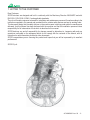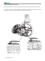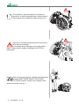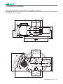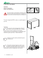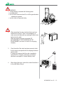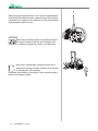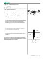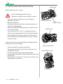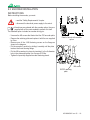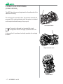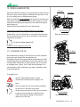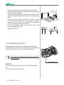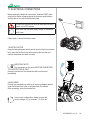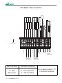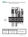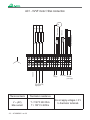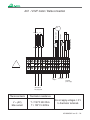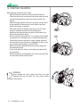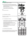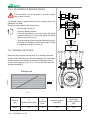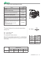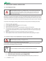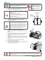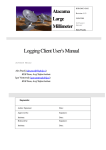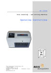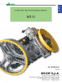
1
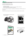
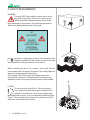
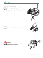
english OPERATION AND MAINTENANCE MANUAL MR10 AC MUM0021 rev. 06 SICOR S.p.A. Head Office and Production Center Viale Caproni 15 (Zona industriale) 38068 Rovereto (TN) Italy Tel. +39 0464 484111 Fax +39 0464 484100 www.sicor-spa.it [email protected] REV. PAGINE - SHEETS DATE INDEX 1. LETTER TO THE CUSTOMER.............................................................................................. 2 2. MACHINE IDENTIFICATION.................................................................................................. 3 3. WARRANTY............................................................................................................................ 4 4. GENERAL DELIVERY NOTES............................................................................................... 5 5. SAFETY PRECAUTIONS....................................................................................................... 6 6. SAFETY REQUIREMENTS.................................................................................................... 7 7. TECHNICAL FEATURES........................................................................................................ 10 8. TRANSPORT.......................................................................................................................... 11 9. NOTES FOR INSTALLATION................................................................................................. 14 9.1. MOTOR ROTATION INSTRUCTIONS 9.2. ENCODER INSTALLATION INSTRUCTIONS 9.3. VENT PLUG POSITIONING (CODE:TAP0025) 10. WINCH LUBRICATION........................................................................................................... 18 10.1. CHANGING THE OIL 10.2. CHECKING THE OIL LEVEL 11. ELECTRICAL CONNECTIONS.............................................................................................. 20 12. STARTING THE WINCH........................................................................................................ 25 13. MAINTENANCE..................................................................................................................... 27 13.1. PREADJUSTMENT OF THE BRAKE 13.2. BRAKE ADJUSTMENT 13.3. CHECKING THE STROKE 13.4. COMPULSORY MAINTENANCE OPERATIONS 14. MANUAL EMERGENCY OPERATING.................................................................................. 31 14.1. WARNINGS 14.2. INSTRUCTIONS FOR AN EMERGENCY MANUAL MANOEUVRE - 1 - AC MUM0021 rev. 06 1. LETTER TO THE CUSTOMER Dear Customer, SICOR winches are designed and built in conformity with the Machinery Directive 2006/42/EC and with EN12100-1, EN12100-2, EN81-1 and applicable standards. They do not therefore represent a hazard for installation and maintenance personnel if used according to the instructions supplied in this manual and provided that the relative safety devices are kept in working order. This document attests that the safety devices on the machine were in working order when the machine was delivered, that this Manual has been delivered with the machine and that the installation personnel takes responsibility for full observation of that which is described in this manual. SICOR declines any and all responsibility for damage caused by alterations to, tampering with and any operations performed on the equipment which do not comply with the contents of the manual, with its instructions or with information provided in other documents. SICOR congratulates you on choosing this product and hopes that you will be impressed by its excellent performance. SICOR S.p.A. AC MUM00021 rev. 06 - 2 - 2. MACHINE IDENTIFICATION When writing to SICOR or Sicor Service Centres with regard to winches, always quote the serial number. Electromagnet data plate Motor data plate Winch data plate - 3 - AC MUM0021 rev. 06 3. WARRANTY 3.1. The warranty, apart from other contractual agreements, is regulated by the following clauses: 3.1.a. The warranty on SICOR products is valid for a period of TWO years from the date of the shipping document. During this period, SICOR will replace free of charge any component recognised as faulty. 3.1.b. A component can be declared faulty only if the fault is recognised by SICOR SpA. 3.1.c. Parts under warranty, to be repaired or replaced, must be sent to SICOR carriage paid. 3.1.d. The Customer must send any request for technical assistance to SICOR in writing. Labour, travel and board and lodging costs must be met by the Customer. 3.2. The warranty lapses automatically when one of the following conditions applies: 3.2.a. The parts for which service has been requested have been tampered with. 3.2.b. The type of application was unauthorised or not agreed beforehand in writing with SICOR. 3.2.c. The use of the machine does not conform to the characteristics for which it was built or to the indications in the technical catalogue or in this “Use and Maintenance Manual”. 3.2.d. 3.3. The warranty does not cover operational parts subject to normal wear and tear: brake linings, bearings, electric windings. 3.4. The warranty does not include indemnity for transport costs or machine stoppage. 3.5. Procedures for action under warranty: 3.5.a. All warranty claims must be communicated to SICOR within 8 days of the anomaly appearing, in writing or by fax. 3.5.b. !" Customer under warranty or will send its own technicians. 3.5.c. Any faulty material replaced by the Customer must remain at SICOR’s disposition for 30 " requested in writing by the company. 3.5.d. Absolutely no claims will be accepted for warranty repairs that were not previously authorised in writing by SICOR. 3.5.e. In all cases, full photographic documentation of repair work must be presented; this is not only for documentary reasons but also to allow SICOR to correct or further improve the quality and reliability of its machines. AC MUM00021 rev. 06 - 4 - 4. GENERAL DELIVERY NOTES Winches can be shipped on pallets or in crates. In all cases, on receipt of the winch, check that: - the packing is undamaged - # "$ - there is no visible damage to the winch or its accessories In the event of damage or missing pieces, immediately send a detailed report to SICOR, its agent, or the shipping agent. Spare parts or parts of equipment of the supply, when necessary, are packed in separate containers. Gear motor complete with accessories according Machine data sheet Work Order MANUALE D’USO E MANUTENZIONE italiano Operation and maintenance manual Box with spare parts (if requested) MR10 AC MUM0021 rev. 04 SICOR S.p.A. Head Office and Production Center Viale Caproni 15 (Zona industriale) 38068 Rovereto (TN) Italy Tel. +39 0464 484111 Fax +39 0464 484100 www.sicor-spa.it [email protected] - 5 - AC MUM0021 rev. 06 5. SAFETY PRECAUTIONS Installation personnel are responsible for making sure that installation and maintenance are carried out in accordance with the essential criteria and requisites for health and safety protection. Installation and maintenance personnel must observe and remain updated as to accident prevention regulations and legal obligations to avoid damage to persons or to the product during installation, maintenance and repair. Important warnings regarding safety and hazards are signalled using the following symbols. WHEN THESE WARNINGS APPEAR, Warning of high hazard risk (e.g.: zones of shearing, cutting, crushing, etc.). Generic hazard warning. Risk of damage to parts of the machinery (for example due to incorrect installation or similar). Symbol to indicate additional important information. PROCEED WITH THE UTMOST CAUTION. %& - INSTALLATION and/or MAINTENANCE PERSONNEL: ' " machine for installation and maintenance operations. AC MUM00021 rev. 06 - 6 - 6. SAFETY REQUIREMENTS WARNING The winch MUST be installed in an area that is strictly kept under lock and key. Access to this area must be '< been authorised by the customer. The following notice must be !<& LIFT MACHINERY DANGER ACCESS TO UNAUTHORISED PERSONNEL IS FORBIDDEN Installers or maintenance personnel must be aware of the dangers associated with the machine and must have read and understood the safety precautions in this manual. Before installing the winch, the customer must verify that the concrete slab and/or the support structures of the shifting loads and the winch meet the required safety factors. The Customer MUST also respect the distances from walls and from other machines in accordance with the directives and standards in force in the country where the winch will be installed. LIFTING To move the winch (see Chap. 8 - Moving the winch) use a suspension-type lifting system connected to the eyebolts on the reduction unit and a non-metallic strap wrapped around the motor, or use an adequately sized forklift (see Chap 7 - Technical features) to lift the winch a maximum of 30 cm *< - 7 - AC MUM0021 rev. 06 EXCLUSION OF POWER SOURCES Before carrying out any cleaning, lubrication and/or maintenance work, maintenance personnel must put the winch out of service by disconnecting the power supply and must wait for the heated parts of the motor and the winch to reach ambient temperature. WARNING Do not lean and/or sit on the winch, either when it is in or out of service. WARNING Do not approach or lean against the rotating parts #*$ AC MUM00021 rev. 06 - 8 - Do not deposit or place any objects or containers of liquids etc. on the hoist and especially on electrical parts. Never tamper with or disable the safety devices or by- pass them or use them for purposes other than those for which they were intended. Do not tamper with or damage or remove the number plates. If deteriorated or illegible, immediately ask SICOR for replacement. When working near the winch, installers and maintenance personnel MUST NEVER WEAR FLAPPING AND/ OR TORN CLOTHING (scarves, cravats, hats, necklaces, belts, watches, bracelets, rings, etc...). - 9 - AC MUM0021 rev. 06 7. TECHNICAL FEATURES =<! More detailed data such as: reduction ratio, absorbed power, number of poles in motor, etc. can be found in the SICOR technical catalogue. 530 150.5 70 222 187 320 150 205 360 ÷ 600 206.5 357 205 330 ÷ 468 370 150.5 205 205 682 AC MUM00021 rev. 06 - 10 - 8. MOVING THE WINCH WARNING RISK OF CRUSHING, IMPACT AND ABRASION The personnel who are responsible for handling the winch must have read the safety requirements in paragraph 6 of this manual and must wear work gloves and safety shoes. The winch is shipped by SICOR in crates or on a pallet wrapped in WARNING Never move the crates by dragging them. Always lift them. Before removing the machine from its packing, To move the crate, use a crane with ropes or an adequately sized forklift with long forks (see Chap. 7 “Technical features”). Furthermore, the forks must be positioned far apart to avoid tipping over. If the machine has been shipped on a pallet, use an adequately sized load spreader when moving with a crane so that the lifting cables or chains are kept in a vertical position and do not damage parts of the machine. - 11 - AC MUM0021 rev. 06 WARNING 1. During handling, remember the following points: a. proceed slowly b. do not lift the crate more than 30 cm off the ground unless obstacles are present. c. lay the crate on the ground slowly 2. When unpacking the crate, start from the top and use suitable tools to open it. Then, if the packaging is a crate, remove the side walls by removing the nails at the bottom from the pallet. When the machine has been unpacked, DO NOT DISPOSE OF THE PACKAGING IN THE ENVIRONMENT, but reuse it or send it to a recycling company. 3. Once the walls of the crate have been removed, check that the supply corresponds with the shipping document and the order. If it does not correspond with the order, immediately notify SICOR or its agent. If necessary, proceed as described in paragraph 4 “General delivery notes”. 4. After slinging the winch, remove the screws that attach it to the pallet before lifting it. AC MUM00021 rev. 06 - 12 - When moving the unpacked winch, use a crane or an adequately sized forklift with wide forks and a suspension-type lifting system connected to the eyebolts on the reduction unit and a non-metallic strap wrapped around the motor. WARNING Make sure that nobody is within the operating range of the means of transport with the winch (danger zone). If the winch is stored for long periods, leave it on its pallet and make sure it is adequately protected (at least with a waterproof covering) to prevent oxidation of the internal or external parts of the machine. Remember that oxidation of the shafts or other mechanical parts reduces their fatigue strength. - 13 - AC MUM0021 rev. 06 9. NOTES FOR INSTALLATION WARNING The location in which the winch is installed must have the following characteristics: - It must be dry and not dusty: this is essential to prevent electrochemical corrosion of mechanical parts and a high concentration of water in the lubricating oil. (clean the machine room before installing the machine). - The room must be ventilated: the room must have adequate openings or conditions that allow air circulation which dissipates the heat from the motor and the reduction unit. - The room temperature must be between 5 °C and 40 °C. . For other temperatures, contact SICOR. 40°c - For positioning of the vent plug (CODE:TAP0025), refer to Chapter 9.3. The customer must make sure that the electrical system where the winch will be installed has suitably gauged cables, is correctly earthed and adequate power is installed. OK 5°c AC MUM00021 rev. 06 - 14 - 9.1 MOTOR ROTATION INSTRUCTIONS Shoe locknut Before rotating the motor, you must: - read the “Safety Requirements” chapter. - disconnect the electrical power supply to the winch. - Position the machine vertically so as not to change the alignment of the motor. - Remove the pulley unit. - Unscrew the locknuts so that there is clearance between the shoes and the drum/flywheel. - Remove the 4 M8x30 fastening screws that connect the motor unit to the winch shaft. - Turn the motor unit 90° or 180° in a clockwise direction (to adapt it to your requirements) until the holes where the screws were inserted are lined up with the holes on the winch shaft. - Put the 4 M8x30 screws and washers back in place. Tighten to a torque of 25 Nm. Left horizontal winch Grid 4X10 screws 4 8X30 screws If rotation of the motor unit causes interference between the drive pulley and the fan, do the following: Right horizontal winch - Open the terminal box and disconnect the fan. - Unscrew and remove the fan unit and the shield grid on the side opposite the shaft. - Put the fan unit back where the grid was fixed before - Using the M4x70 and M4x10 screws, refasten the fan unit and the shield grid - Reconnect the fan cables in the terminal box according to the wiring diagram in the manual Fan unit M4X70 screws Vertical winch - 15 - AC MUM0021 rev. 06 9.2 ENCODER INSTALLATION INSTRUCTIONS Before installing the encoder, you must: - read the “Safety Requirements” chapter. - disconnect the electrical power supply to the winch. If machines are ordered with the encoder option, they are supplied with all the parts needed to perform this task. The standard option includes an encoder driving pin. - Unscrew the M3 screws that fasten the Lika C50 encoder plate. - Remove the retaining plate and replace it with the one supplied by Sicor. - < [ \] * shown in the diagram. - Put the encoder in position by sliding it coaxially until the plate * - Put the M8 screw back in place by inserting it in the 9-diameter hole in the plate and tighten it to a torque of 25 Nm. - Tighten the specially supplied encoder fastening dowel. Detail of winch with encoder option M8 screw SICOR retaining plate AC MUM00021 rev. 06 - 16 - 9.3 VENT PLUG POSITIONING (CODE:TAP0025) The MR10 winch has a vent plug located on the pulley side of the reduction unit casing. The vent plug acts as a safety valve. The pressure caused by the movement of the rotating elements within the gearbox is released via the labyrinth without allowing oil to spray out. Left horizontal winch The winch is delivered in a horizontal left or right < In the event that it is positioned vertically, reposition the vent plug as shown. Right horizontal winch Vertical winch - 17 - AC MUM0021 rev. 06 10. WINCH LUBRICATION Oil level Shell Omala S4 WE synthetic oil is supplied with the winch. Ensure that the oil drain screw is tightly closed and check that the oil level is at the halfway point on the transparent gauge. Shell Omala S4 WE is non-miscible with mineral oils and with most other types of synthetic lubricants. Be careful, therefore, to avoid ! when topping up. Mineral oils are not permitted for use in the machine. The exclusive use of Shell Omala S4 WE oils is advisable. Contact Sicor s.p.a. for information on using lubricants other than those indicated in this manual, and for instruction on the relevant replacement procedure. Oil discharge Right horizontal winch Do not use other types of oil! The MR10 winch requires 3 litres of oil. 10.1 CHANGING THE OIL We recommend to change oil after 600 hours of winch operation, *! Subsequent lubricant changes should be performed every 24/36 months depending on the conditions of use of the machine. If the oil temperature exceeds 85 °C (during intense use), the oil must be changed every 2 years. The oil must also be changed if it is contaminated by other substances (e.g. water or topping up with unrecommended oil). To change the oil: Oil discharge Vertical winch Oil level Oil level - read the “Safety Requirements” chapter. - disconnect the electrical power supply to the winch. - wait for at least one hour from machine shutdown so that the oil in the winch cools down. - to prevent from entering dirt or deposits which could cause serious damage to the machine - < Oil discharge Left horizontal winch AC MUM00021 rev. 06 - 18 - - place a container under the drain plug to collect the used oil - unscrew and remove the drain plug and wait a few minutes for the tank to drain completely. - clean the drain plug and the area where it is housed with a cloth; tighten the plug and make sure to also insert the washer; tightly fasten. - cap and the area surrounding it to prevent dirt or deposits entering the winch. Failure to comply with these instructions may cause serious damage to the machine. - pour the oil through a clean spout until the level on the transparent gauge is reached. - 10.2 CHECKING THE OIL LEVEL Checking the oil level can be done immediately by checking the transparent gauge. If the oil level is low, top up using the same type of oil that is in the winch. To top up, follow the above steps. The oil level must be checked when the machine has been off for at least 30 minutes. Oil level gauge WARNING < of it. Do not release into the environment. - 19 - AC MUM0021 rev. 06 11. ELECTRICAL CONNECTIONS Before making the electrical connections, installers MUST make < All electrical connections must be made with the main switch in the OFF position. Make sure that the rated supply voltage is maintained at all times. If they match, connect the electric motor. 1 ELECTRIC MOTOR Using the wiring diagram (which can be found in the motor terminal box), make the electrical connections and make sure that you connect the phases and earth correctly. IMPORTANT NOTE Any thermistors on the motor MUST BE CONNECTED TO A SPECIFIC RELAY ONLY. Incorrect connection of the thermistors will burn them out immediately. 2 AUXILIARIES Connect any auxiliaries by referring to the wiring diagram placed under the terminal box cover or enclosed with this manual. After connecting, close the terminal box. correct voltage (V~) to terminals 1, 2 of the fan. AC MUM00021 rev. 06 - 20 - AC2 Motor / Star connection 2U2 1W2 1V2 1U2 2W1 2V1 2U1 1W1 1V1 1U1 Series-connected coils 2V2 Thermistors 2W2 Thermocontacts Fan Star point Star point GND L1 L2 L3 (three-phase line) High speed Fan voltage~ L1 + DC Brake power supply L3 (three-phase line) Low speed Thermocontacts Thermistors resistance V ~ (AC) Max current T < 150°C 300 Ohm T > 150°C 4 KOhm - 21 - AC MUM0021 rev. 06 L2 Thermistors Do not apply voltages > 5 V to thermistor terminals AC2 motor / delta connection 2U2 1W2 1V2 1U2 2W1 2V1 2U1 1W1 1V1 1U1 Series-connected coils 2V2 Thermistors 2W2 Thermocontacts Fan Star point Star point GND L1 L2 L3 (three-phase line) High speed Fan voltage~ L1 L2 Thermistors + DC Brake power supply L3 (three-phase line) Low speed Thermocontacts Thermistors resistance V ~ (AC) Max current T < 150°C 300 Ohm T > 150°C 4 KOhm Do not apply voltages > 5 V to thermistor terminals AC MUM00021 rev. 06 - 22 - AC1 - VVVF motor / Star connection 2U2 2W1 2V1 2U1 Series-connected coils 2V2 Thermistors 2W2 Thermocontacts Fan Star point GND Fan voltage~ L1 L2 Thermistors + DC Brake power supply L3 (three-phase line) High speed Thermocontacts Thermistors resistance V ~ (AC) Max current T < 150°C 300 Ohm T > 150°C 4 KOhm - 23 - AC MUM0021 rev. 06 Do not apply voltages > 5 V to thermistor terminals AC1 - VVVF motor / Delta connection 2U2 2W1 2V1 2U1 Series-connected coils 2V2 Thermistors 2W2 Thermocontacts Fan GND Fan voltage~ L1 L2 Thermistors + DC Brake power supply L3 (three-phase line) High speed Thermocontacts Thermistors resistance V ~ (AC) Max current T < 150°C 300 Ohm T > 150°C 4 KOhm Do not apply voltages > 5 V to thermistor terminals AC MUM00021 rev. 06 - 24 - 12. STARTING THE WINCH Before placing the cables on the pulley: - \" - Check that the electric connections have been made correctly and that the terminal box covers have been put back into position. - {* at high speed for a few seconds in one direction and then, after a short pause, in the other. - |#}$* along the channels and lubricate the rotating parts. - Make sure the brake releases correctly as described in the sheet enclosed with the winch. - Run the machine without load for 3 ÷ 5 minutes at high speed and make sure no anomalies occur. If malfunctioning occurs, recheck the electrical connection, supply voltage, absorbed current and/or the way the winch is clamped to its base. If you are uncertain about anything, contact SICOR. - \"* last step and recheck. - At this point, place the cables on the pulley and perform the - Make sure that the counterweight is the correct size and does not overload the winch and the motor. WARNING Never operate the winch under load when the base fastening bolts are not tight! This may cause serious damage to the machine! - 25 - AC MUM0021 rev. 06 OK IMPORTANT When installing the lift, do not operate the winch for long periods at low speed. When the winch operates for long periods at low speed, the machine supports are not lubricated properly and may seize up unexpectedly. To ensure proper lubrication, always start the winch at normal operating speed each time work is begun and then run at high speed every half hour. START-UP/SHUTDOWN The customer is responsible for the procedures, instructions and wiring diagrams for the start-up and shutdown of the winch. NEVER USE THE WINCH FOR PERFORMANCES ABOVE THOSE INDICATED IN THE TECHNICAL CATALOGUE. DISPOSAL OF THE WINCH AT THE END IF ITS SERVICE LIFE Drain the machine of its lubricating oil and then: - Deliver the oil to a company that is authorised to dispose of it. - Deliver the winch to a company that is authorised to recycle ferrous materials. AC MUM00021 rev. 06 - 26 - 13. MAINTENANCE Before carrying out any maintenance work, MAKE SURE YOU HAVE read paragraph 6 “Safety requirements” in this manual. Installing and/or maintenance may only be done by competent personnel, authorised to access the machinery and having the necessary equipment and instruments. WARNING Before starting any installation and/or maintenance work, attention must be given to the safety requirements given below in order to avoid accidents and damage to the product components: - Make sure you have the appropriate personal protection equipment (helmet, body harness, gloves, safety shoes). - Always secure equipment and other objects to avoid them accidentally falling from a height. - Make sure that the power has been disconnected before working on electrical equipment. - Only install the electrical system and/or the connections once you have read the relative instructions. - Before starting installation, see if there are any structural and space limitations where the installation / maintenance work will be carried out. - It is advisable to consider where and when you will be operating and which assembly/maintenance procedures you will use. - " < "<' Installers/maintenance personnel must provide a maintenance plan in relation to the use characteristics of the winch. Routine maintenance of the winch is limited to: - Lubrication of the winch (see page 18) General cleaning of the winch Brake adjustment Assessment of wear and tear of brake linings Assessment and checking of wear and tear of pulley grooves Some reduction ratios have a partial degree of reversibility, in such conditions the opening on the machine brake can generate cab and counterweight movement. Before manually opening the brake therefore, ensure that the counterweight is resting on the shock absorbers and that the cab cannot be accessed. - 27 - AC MUM0021 rev. 06 13.1 PREADJUSTMENT OF BRAKE Values to be set before installing the winch suspension cables: - check that the brake has not sustained damage during transport, loosen and remove the nuts (4) and (3) and then remove the guard from the brake drum, - adjust the spring using the relative nut (3), - secure the adjustment using the locknut (4), - to adjust the stroke, see the relevant paragraph. N.B. * 3 4 L = 55mm “CLOSED” “OPEN” “OPEN” 13.2 ADJUSTMENT OF BRAKE 1 2 5 6 5 2 1 The brake has two separate magnets so that the shoes operate independently of each other. 13.2.1 ADJUSTMENT OF STROKE - Loosen the locknuts (2) on both the brake shoes and unscrew the adjusting screw (1) leaving a clearance of 4-5 mm between the screw and the electromagnet pin (5), - turn the brake opening lever (6) to the “open” position, - #$ * with the electromagnet pin (5), - turn the brake opening lever (6) to the “closed” position and tighten the adjusting screw half a turn against the electromagnet pin, - tighten the locknuts (2). 13.2.2 CHECKING THE ADJUSTMENT Move the cab up and down and listen to the noise level. The stroke is correctly adjusted if the brake lining does not touch the brake drum while the lift is moving and no noise is heard when braking. Lift speed [m/sec] Braking distance [cm] high low 0.4 8 10 0.5 13 16 0.6 18 22 0.75 28 35 1.0 50 62 1.2 72 90 1.6 128 160 AC MUM00021 rev. 06 - 28 - 13.2.3 ADJUSTMENT OF BRAKING TORQUE If this procedure is not done correctly, the brake system may not work correctly. The braking torque is adjusted when the cab is empty (values are indicated in the table). Repeat the same steps for both brake shoes: - Unscrew the locknuts (4). - Check the braking distance. - If the braking distance is too short, loosen the spring by turning the nut (3). If it is too long, tighten the spring again by turning the nut (3). - Once the braking distance has been adjusted correctly, check that the springs are of the same length. Secure the adjustment using the locknut (4). 3 4 L 13.3 CHECKING THE STROKE 1 2 5 6 5 2 Make sure that the brake opening lever (6) is centrally positioned (brake closed). Manually press the electromagnet pin (5) right down and then measure the clearance between the adjusting screw (1) and the electromagnet pin (5). If it is < 0.5 mm, the stroke must be adjusted immediately. Braking torque 120 100 Torque [Nm] 80 60 — C nom. 40 20 0 58 53 L [mm] Machine type D (Ø Brake drum) [mm] L (minimum) [mm] Maximum braking torque [Nm] Brake lining [Nm] MR10 276 55 100 0.44 - 29 - AC MUM0021 rev. 06 1 13.4 COMPULSORY MAINTENANCE WORK Check Frequency oil level 4 months Gm * thickness of brake linings adjustment of opening of brake shoes 2 months wear and tear of pulley grooves 6 months (acoustic) of condition of bearings 6 months (acoustic) of presence of abnormal noise levels 6 months gear backlash measured as shown in the #"! backlash of the screw) 12 months Rp *The nominal thickness is 6 mm, and must be replaced before Rpr G = Gm x reaching 2 mm. Rp Rpr = pitch radius of gear Rp = radius of pulley Gm measurement of pulley clearance When the “G” gear backlash exceeds value “ G* ”, indicated below, the gear must be replaced because it no longer offers the required level of safety. R.R. Rpr [mm] 43/1 86.3 43/2 86.3 55/1 89.1 55/2 89.1 Reduction ratio G* (mm) 43/1 43/2 55/1 55/2 0.68 0.68 0.59 0.59 AC MUM00021 rev. 06 - 30 - 14. EMERGENCY MANUAL MANOEUVRE 14.1 RECOMMENDATIONS Manual emergency manoeuvre is a dangerous task. It can be used to move the cab excluding all the plant safety contacts. For this reason, anyone who performs this operation must have been carefully trained by specialised personnel and must be aware of the risks involved. Assistance in the event of an emergency must only be provided by expert, specially trained personnel. All the operations performed in the event of an emergency must strictly follow the instructions in this manual. A copy of this document must therefore be kept near the storage area and be easy to access if necessary. In the event of an emergency entailing manual manoeuvres strictly observe the following instructions: 1. 2. 3. 4. 5. 6. 7. Follow local safety requirements. Do not neglect the safety of passengers at risk in any way. Do not put them at risk in any way. Make sure that their actions do not create hazardous situations for third parties. Communication with any passengers in the cab must be established as soon as possible in order to reassure the people present. This can help to establish the position of the cab in the well more precisely. < After completion of work, make sure there are no problems with normal operating of the plant. 14.2 INSTRUCTIONS FOR AN EMERGENCY MANUAL MANOEUVRE Manual emergency operating is a dangerous task It can be used to move the cab excluding all the plant safety contacts. For this reason, anyone who performs this operation must have been carefully trained by specialised personnel and must be aware of the risks involved. For correct emergency manual operating, carefully follow these instructions. 1. 2. 3. 4. "* " *< Put the main switch on the control panel to the OFF position. Reassure the passengers in the cab, explaining to them exactly what you intend to do. - 31 - AC MUM0021 rev. 06 Passengers must not try to force open the cab doors or try to get out of the cab. 5. Check that the operating conditions of the main brake and winch are safe for moving the cab. To see if the main brake on the winch is working properly, check: - if the brake shoes are broken - if the brake linings are damaged which limits the contact surface - if contact with the braking surface is uniform 6. Never loosen the tension of the brake springs to make manual emergency operating easier. BRAKE ON (brake shoes closed) BRAKE OFF (brake shoes open) POS 1 POS 2 Check rotation direction of the winch for the cab movement manoeuvre. If the winch and/or the main brake are out of use or the safety is inserted, perform the rescue procedure and ensure that the cab is secure by using a special device suitable for the type of plant, place and operating conditions. 7. 8. 9. 10. 11. 12. 13. \ "* Release the main brake using the special manual lever (POS 2). Begin manual operating to move the cab to the required * * direction. Release the manual release lever of the main brake on the winch and check that it goes back to the off position (POS 1). Open the cabin doors and help the passengers. * "* cannot be opened in any way. "#$ the relevant manual. AC MUM00021 rev. 06 - 32 - SICOR S.p.A. Head Office and Production Center Viale Caproni 15 (Zona industriale) 38068 Rovereto (TN) Italy Tel. +39 0464 484111 Fax +39 0464 484100 www.sicor-spa.it [email protected]