1
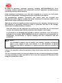
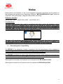
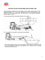
USE AND MAINTENANCE MANUAL
BOOMS SKIPLOADER
MB 16
INDEX
PREFACE
LIABILITY DECLARATION
PART I - BOOMS SKIPLOADER USE
SAFETY STANDARDS
SAFETY DEVICES AND PROTECTIONS
EMERGENCY DEVICE
IDENTIFICATION
MAIN COMPONENTS
TECHNICAL DATA
INSTRUCTIONS FOR USE
PNEUMATIC SYSTEM
OLEODYNAMIC SYSTEM
ELECTRICAL UNIT
PART II - BOOMS SKIPLOADER MAINTENANCE
MAINTENANCE INSTRUCTIONS
FUNCTIONING ANOMALIES
MAINTENANCE PROGRAM
3
PREFACE
This manual contains MECCANIDRAULICA S.p.A. booms skiploader use and
maintenance instructions, as well as basic safety standards.
CAREFULLY READ THIS MANUAL before starting any operation related to the
equipment in order to avoid material damages to the new machine made of lorry with
cab, booms skiploader, and skips being used, risking the safety of the operator or of
other people or animals, as well as useless waste of time during the installation and
use of the booms skiploader.
Installation must be performed by MECCANIDRAULICA S.p.A. authorised workshops
following instructions in this manual
In the event of assemblies assigned to workshops without sufficient technical abilities
to perform set-up in a way that is compliant with MECCANIDRAULICA S.p.A., all
responsibility and warranty is declined.
The following instructions may be completed by the user manual provided by the
supplier who will include information concerning parts used during booms skiploader
assembly and any usage reduction of its capacity.
The booms skiploader must be exclusively operated by responsible persons who have
already been instructed and authorised to operate the machine.
THANKS FOR CHOOSING ONE OF OUR PRODUCTS
4
LIABILITY DECLARATION
MECCANIDRAULICA S.p.A. DECLINES ANY LIABILITY FOR DAMAGE
CAUSED BY:
- by an installation that does not conform to the requirements contained in this
manual
- use of the loader crane by unauthorised people.
- non-compliance of the maximum admissible load and of the use instructions.
- wrong manoeuvres during use
- any removals or tampering of the safety systems
- people or objects present in the work area
- failure to comply with the prescribed checks and routine maintenance (in particular
regarding lubrication
- interventions or modifications on the equipment without MECCANIDRAULICA S.p.A
authorisation
- use of non original spare parts
5
The present manual contains all information necessary for a correct installation,
use and proper booms skiploader maintenance.
MECCANIDRAULICA S.p.A. makes it obligatory for personnel in charge of driving the
equipment and maintenance, along with personnel in charge of transport and assembly
operations, to read this document.
This document is the Booms skiploader instructions manual and it is prepared in
conformity to the 2006/42/CE Directive.
The Use and Maintenance manual is to be considered an integral part of the equipment
and must be kept until final disposal.
It must be kept by the manager that the equipment is entrusted to after final installation.
The manual reflects current technique at the time the equipment is marketed and cannot
be considered inadequate only as a result of subsequent updates based on new
experience, besides, MECCANIDRAULICA S.p.A. reserves the right to update production
and manual without the requirement of updating preceding production and manuals.
The above mentioned equipment may throughout time need the replacement of
components, for this purpose the purchaser can perform the order of the components to
be replaced. The customer (purchaser) is obliged to always buy original spare parts. For
any request concerning the ordering of spare parts for the equipment which is the
subject of this document, one must always specify the model and serial number to which
the spare part refers to as per indications on the identification name plate.
Orders must be completed at our MECCANIDRAULICA S.p.A. Customer After-Sales Service
centres.
6
MECCANIDRAULICA S.p.A. provides the After-Sales service for customers in order to resolve
any problem related to equipment use and maintenance.
Customers may send their requests to:
MECCANIDRAULICA S.p.A.
Via. Gratteria, 3/F
12084 MONDOVÌ (CUNEO) - ITALY
Phone : 0039.0174.552956
Fax
: 0039.0174.552853
E-mail [email protected] - www.mecspa.net
“CE” declaration of conformity
The following equipment also includes the CE declaration of conformity. (Attached to this
manual)
CE Declaration of Conformity
(Compliant Annex II - Section A - Directive 2006/42/CE)
MECCANIDRAULICA S.p.A.
with its headquarters in
Via. Gratteria, 3/f
12084 MONDOVI’ (CN)
Declares on its own responsibility that the machine:
BOOMS SKIPLOADER
S/N XXXXX
Year of manufacture XXXX
conforms to the essential safety requirements indicated in Annex I of Machinery Directive
2006/42/CE,
in
particular
with
reference
to
the
following
dispositions:
EN12100-1:2009 – EN12100-2:2009 – EN13857:2008 - EN349:2008 – EN13850:2008 EN60204-1:2006 - EN982:2008 – EN983:2008 – EN1037:2008 – EN1088:2008 - EN
ISO11202:2009 - EN574:2008 - EN953:2009.
7
Warnings and warranty
MECCANIDRAULICA S.p.A. creates and designs its own equipment in total compliance to
the safety standards in force, with the aim to assure the user has the maximum
guarantee in exercising all foreseen and permitted operations, together with the
minimum possibility of accidents due to any residual risks.
Even after the commissioning, MECCANIDRAULICA S.p.A may perform modifications to
the equipment, modifications that at its discretion represent improvements for the
functioning.
MECCANIDRAULICA S.p.A. guarantees that the equipment is free of material or
construction defects for a period of twelve months from the date of the final inspection
carried out by the purchaser, always subject to the different contractual conditions.
During this period MECCANIDRAULICA S.p.A. commits to repair or replace, in the
necessary time, those parts that are faulty and/or defective in origin as long as the
purchaser informs MECCANIDRAULICA S.p.A. via registered letter, within seven days
from the discovery. As per above subject to the different contractual conditions. Any
further obligation and/or compensation from MECCANIDRAULICA S.p.A. are however
excluded.
The above warranty (or the contractual one) is only applied is the Purchaser has followed
contractual requirements and exclusively if equipment installation and subsequent use
are carried out by the Purchaser according to instructions contained in the installation
manual.
The warranty excludes any possible responsibilities for direct or indirect damages to
people and things deriving from the unsuitable use or maintenance of the equipment
mentioned above. This warranty does not extend to the replaced or repaired parts. The
parts that for their specific use are subject to wear and tear are also excluded from the
warranty. Finally, the transport, survey, disassembly and reassembly costs, due to the
intervention of a MECCANIDRAULICA S.p.A. technician, are excluded from the warranty
and shall therefore be charged to the Purchaser, should the encountered faults and/or
defects not be covered by this warranty, as per above subject to the different contractual
conditions.
The warranty expires automatically in the event of repairs, modifications or removals,
components replacements not previously communicated or agreed and approved by
MECCANIDRAULICA S.p.A. One must never use the equipment nor perform any
intervention on it, if beforehand one has not carefully read and fully understood this
booklet in all its parts. It is forbidden to use the equipment in different conditions or for a
different use than those indicated in this booklet. MECCANIDRAULICA S.p.A. cannot be
held responsible for breakdowns, inconveniences or injuries due to the non compliance
to this prohibition. It is forbidden to tamper with or alter, even partially, the installed
safety devices.
8
PART I
BOOMS SKIPLOADER USE
9
USAGE SAFETY STANDARDS
General warnings
In order to use the booms skiploader correctly, it is necessary to know its operation
and the warranty standards specified in the Warranty certificate.
It is therefore important to read this manual before booms skiploader start-up and use.
Replace warning, instruction and manoeuvre plates that are no longer legible or are
missing.
Warnings for operative phases
Here below is a reproduction of the plate containing safety standards instructions
which is applied in proximity of the controls and is visible to the operator.
SAFETY STANDARDS
Booms skiploader manoeuvring and use are exclusively reserved
to personnel in charge.
Do not operate in proximity of electrical power lines.
During booms skiploader use the vehicle must:
• be placed on level and solid ground
• the emergency brake must be engaged and using the
appropriate wedges
• it must be protected against tipping using the stabilisers
Before starting each manoeuvre make sure that:
• no one is within the booms skiploader range of action (minimum
distance is 10 m)
• safety devices are efficient
• the established minimum safety distances from electrical power
lines are observed even during skips overturning.
Gradually manoeuvre the booms skiploader avoiding sudden load
starting and stopping.
Avoid load oscillations and skewed pulls.
Do not allow any part of the load to protrude from booms
skiploader because during loading and transport it may fall to the
ground.
Disengage power take-off before re-engaging gear and make sure
that stabilisers are retracted and the relative warning light is
switched-off.
10
Reference standards and legal regulations
MACHINERY SAFETY STANDARDS
EN
EN ISO
349
13850
2008
2008
Minimum gaps to avoid crushing of parts of the human body.
Emergency stop devices, functional aspects. Principles for design
EN
547-1
2008
Safety of machinery - Human body measurements - Principles for determining the dimensions required
for openings for whole body access into machinery
EN
547-2
2008
EN
547-3
2008
Safety of machinery - Human body measurements - Principles for determining the dimensions required
for access openings
Safety of machinery - Human body measurements - Anthropometric data
EN
614-1
2009
Safety of machinery - Ergonomic design principles - Part 1: Terminology and general principles
EN ISO
13857
2008
Safety distances to prevent hazard zones being reached by upper and lower limbs
EN
842
2008
EN
894-1
2008
EN
894-2
2008
EN
894-3
2008
EN
953
2009
Safety of machinery. Visual danger signals. General requirements, design and testing.
Safety of machinery - Ergonomics requirements for the design of displays and control actuators General principles for human interactions with displays and control actuators
Safety of machinery - Ergonomics requirements for the design of displays and control actuators Displays
Safety of machinery - Ergonomics requirements for the design of displays and control actuators Control actuators
Safety of machinery - Guards - General requirements for the design and construction of fixed and
movable guards
EN ISO
13849-1
2008
Safety of machinery - Safety-related parts of control systems - Part 1: General principles for design
EN
981
2008
Safety of machinery - System of auditory and visual danger and information signals.
EN
982
2008
EN
999
2008
EN
EN ISO
1037
14121-1
2008
2007
Safety of machinery - Safety requirements for fluid power systems and their components - Hydraulics
Safety of machinery - The positioning of protective equipment in respect of approach speeds of parts of
the human body
Safety of machinery - Prevention of unexpected start-up
Safety of machinery - Risk assessment - Part 1: Principles
EN
1032
2008
Mechanical vibration - Testing of mobile machinery in order to determine the vibration emission value
EN
1088
2008
Safety of machinery - Interlocking devices associated with guards - Principles for design and selection
EN
1299
2008
Mechanical vibration and shock - Vibration isolation of machines - Information for the application of
source isolation
EN ISO
4871
2009
Acoustics - Declaration and verification of noise emission values of machinery and equipment
EN ISO
11200
2009
Acoustics - Noise emitted by machinery and equipment - Guidelines for the use of basic standards for
the determination of emission sound pressure levels at a work station and at other specified positions
EN ISO
11202
2009
EN ISO
UNI
UNI
UNI
UNI
EN ISO
EN ISO
EN
EN
EN
EN
EN
11161
7543-1
7543-2
7543-3
7544-1/16
12100-1
12100-2
61000-6-4
61000-6-2
60204-1
61310-1/2/3
50110-1
2007
2004
2004
2009
1976÷2008
2009
2009
2007
2005
2006
2008
2005
Acoustics - Noise emitted by machinery and equipment - Measurement of emission sound pressure
levels at a work station and at other specified positions - Survey method in situ
Safety of machinery - Integrated manufacturing systems - Basic requirements
Colours and safety signals - Part 1: General requirements
Colours and safety signals - Part 2: Colorimetric and photometric properties of materials
Colours and safety signals - Part 3: Warnings
Graphic symbols for prohibition signs.
Basic concepts, general principles for design - Basic terminology, methodology
Basic concepts, general principles for design - Technical specifications and principles
Second edition - Generic standards - Emission standard for industrial environments
Third edition - Generic standards - Immunity for industrial environments
Electrical equipment of machines - General rules
Safety of machinery - Indication, marking and positioning
Second Edition - Live electrical work - Operation of electrical installations
11
In order to guarantee maximum operating reliability, MECCANIDRAULICA S.p.A.
accurately chooses materials and components used for equipment manufacturing by
periodically testing it before delivery.
Good equipment performance over time also depends on a correct use and proper
preventive maintenance, following instructions contained in this manual.
All manufacturing elements, connection and control parts are designed and
manufactured with a degree of safety that allows resistance to anomalous stress or any
that exceeds what is indicated in this manual.
Materials are of the best quality and their introduction to the company, storing and use in
the workshop is constantly checked in order to guarantee that there is no damage,
deterioration or malfunctioning. In addition:
− One must never use the equipment nor perform any intervention on it if beforehand
one has not carefully read and fully understood this booklet in all its parts.
− It is forbidden to use BOOMS SKIPLOADER in different conditions or use from what is
indicated in the booklet. MECCANIDRAULICA S.p.A. cannot be held responsible for
breakdowns, inconveniences or injuries resulting from non compliance with this
prohibition.
NOTE:
It is forbidden to tamper, alter of modify, even partially, systems or equipment
which is the subject of this user manual. It is also forbidden to operate
differently from what is indicated or to ignore operations that are necessary for
safety.
It duty of the operator to keep the equipment clean from foreign materials such as debris
or other.
The use of compressed air for cleaning requires the use of protective goggles and mask;
it is also necessary to make sure that no one is near the equipment to keep them from
being hit by materials or dust.
12
It is forbidden to use inflammable fluid during cleaning operations.
Periodically verify name plates status and recovery them if necessary.
Once equipment cleaning is complete, the operator must verify that no parts are worn, damaged
(if noticed, immediately request intervention on the part of the maintenance technician) or not
solidly fastened (intervene as possible based on capability).
Equipment safety protections and devices cannot be removed unless it is necessary for a repair
and/or maintenance intervention. Particular attention must be given to state of integrity flexible
piping or of other parts subject to wear. It is also necessary to verify that there are no leaks of oil
or other dangerous substances.
If that occurs, it is forbidden for the operator to restart the machine before the situation has been
remedied. Personnel must wear suitable protective clothing according to needs and
characteristics of the work being executed, such as:
Helmet for protecting the head from the risk of material falling from above.
Safety goggles and masks protecting from splinters or from the presence of thick dust (if
compressed air is used as a flushing device, it is recommended to include a means for
collecting dust).
Safety gloves and shoes.
Personnel must also wear suitable work clothing, without loose parts that may get caught in
moving mechanical elements.
While carrying out work that may cause chips or material projection, this is dangerous to oneself
or others operating in close proximity, the operator must use adequate safety measures or ask
for them from those in charge.
Machine safety protections and devices cannot be removed unless it is necessary for a repair
and/or maintenance intervention.
They must be restored as soon as the reasons that made their temporary removal necessary
are over and, in any case, before starting the machine.
One declines all responsibility for any accidents or damages to people or things deriving from
the failure to comply with the regulations relative to safety, for performed operations that are not
contained in this Manual and after any modification that has not first been authorised in writing
by the manufacturer.
13
The safety standards described in this Manual integrate and do not replace the national and
European safety standards and any internal laws in force.
Use the equipment for purposes and in the operating conditions specified in this manual.
Maintain and periodically check all the devices directly pertaining to safety, do not remove the
safety guards when the equipment is in movement.
Keep boxes and electrical boxes closed.
Keep under control all the elements subject to possible wear and tear. In particular, this applies
for all the mechanical elements in movement and for all the pipework, cables and wiring in
movement, especially the ones subject to high stress and operating pressure.
Avoid cleaning, lubricating or maintaining the elements in any way during their movement. Place
the equipment in stable still condition before proceeding with such operations.
In the event of a fire use suitable extinguishing agents and in any case do not use WATER to
extinguish the fires.
All the checks and maintenance operations on the equipment and in particular those that require
the removal of safety protection devices and access to dangerous parts must only be performed
by authorised and adequately qualified personnel. (Contact MECCANIDRAULICA S.p.A.
authorised workshops)
Perform maintenance checks as per the chapter relative to Maintenance.
Do not attempt to make repairs that one does not know. Carefully follow the usage warnings.
If compressed air is used during the cleaning operations, wear a protective visor.
Check the efficiency of the power disconnecting device.
Check the efficiency of the equipment earthing.
There must NOT be any unauthorised people in proximity of the equipment whilst it is in
operation.
DO NOT put hands inside the machines whilst they are in operation; particularly do not insert
hands or fingers in mobile elements.
Avoid performing any manoeuvre that does not concern the permitted operations, whilst the
equipment is in function.
14
DO NOT approach with loose clothing that may get caught in the mobile parts of the equipment.
Carefully read and follow the attached signs, do not cover them under any circumstances and
replace them if they get damaged.
DO NOT rest on the equipment in any point and under any circumstances.
DO NOT rest tools and objects on the mobile parts.
DO NOT rest liquid containers near the electrical parts.
DO NOT wash the equipment with direct water jets, liquids or corrosive substances.
DO NOT obstruct or damage the safety devices or use them for different purposes other than
those designed by the manufacturer, but check their efficiency often and clean them frequently.
DO NOT modify under any circumstances parts of machines such as connections, drillings,
finishes, etc., to add other devices; in the event of malfunctioning due to not complying with the
above the manufacturer is not liable for the consequences. We recommend requesting any
modifications directly to the construction firm.
Clean the painted coverings of the machines, the panels and the controls with soft and dry
cloths or ones that are slightly soaked with a mild detergent solution. Do not use any type of
solvent or petrol because the surfaces may get damaged.
DO NOT leave the equipment unattended whilst in operation.
Danger of Explosion: The equipment concerned IS NOT DESIGNED to work in an
environment with the formation of explosive atmospheres
15
Noise
Determination and indication of the A level-weighted equivalent continuous sound pressure in
the workplace as required by the "Machinery Directive". MECCANIDRAULICA S.p.A. made the
equipment, during the design, using the best possible technology.
Reference standard
UNI EN ISO 11200 – UNI EN ISO 11202 – UNI EN ISO 4871
Considerations
The noise measurements were made in accordance with what is set by the standard in force.
The daily exposure of operating staff to noise can be reduced by applying some simple
precautions. Noise in the operator station mainly derives from the power source (HYDRAULIC
CONTROL UNIT) and can determine significant dangers. Whilst manoeuvring the equipment it
is recommended to use appropriate hearing protection Devices.
The parts of the equipment that produce noise, must be periodically checked and replaces by
the same ones used by MECCANIDRAULICA S.p.A. present in the bill of material. It is
recommended to perform these checks every time an increase of noise is detected.
1.1
Electromagnetic Compatibility
The WIRING of the equipment is kept in compliance with the requirements of the standards in
force and in particular with the requirements of standard CEI EN 60204-1:2006 “Safety of
machinery - Electrical equipment of machines —-Part 1: General Rules"
The ENGINE used does not create major disturbances during normal functioning. Engines have
been adopted which do not cause significant voltage drops when starting and are used in their
nominal conditions, as well as being CE marked by the manufacturer.
With regard to immunities, the electrical unit is compliant with EN 61000-6-2:2006.
With regard to emissions, the electrical unit is compliant with EN 61000-6-4:2007.
16
INTENDED,
USES
NOT
INTENDED,
INCORRECT
The equipment must be used for:
− Loading and Unloading interchangeable containers loaded with waste to be destined
to the garbage dump or to recycling companies.
− Overturning and resulting unloading of material inside the bins.
Equipment cannot therefore be used for any other operation that is not among those
listed.
In particular the equipment cannot be used to move, push, pull or force any ground or
mobile structure that is not allowed; the equipment must not be connected hydraulically,
electrically or mechanically with any other machinery to carry out energy exchange; the
equipment cannot be used as a device for lifting any kind of load.
The operations for which the structure was designed and built are also potentially
hazardous because they concern handling of heavy mechanical parts, with related
movement, in a way that is not possible to protect in any way the concerned areas.
They are therefore operations that must be carried out with full knowledge, on the part of
the operator, that the work area must be cleared and no one can be present in the same
area.
17
RESIDUAL RISKS AND EMERGENCY SITUATIONS
As far as equipment operation and safety, the following residual risks have been located and
require the following operational carefulness (resulting from specific instruction, training and use
of recommended PPE equipment):
-
mechanical risks from moving parts
risks caused by the oil used in control units and lubricants
Mechanical risks from moving parts
The equipment is necessary for handling (unloading/loading) bins on lorries made
of metal or a different material.
Since it is not possible to install metal guards in proximity of dangerous areas, in
order to avoid mechanical risks caused by moving parts, there is a residual risk of
crushing, entrapment and shearing between the parts.
This is a risk that must absolutely be avoided through specific operator training.
They must absolutely know the required conditions for movements to be carried
out.
In particular:
- He must wear the necessary PPE;
-
the operator must activate the equipment from the control position in the cab or from
the ground, through the remote push-button panel or the hydraulic controls on the
frame, making sure that his position is secure
-
IN EACH CASE the operator must ascertain that there is no person the in the work
area
-
The operator must follow procedures as indicated in the specific section in the
present manual.
18
“Chemical” risks from oil and lubricants
The safety sheets for chemical products (hydraulic oil and lubricants) used in the equipment and
recommended are included as attachments.
There is a residual risk resulting from the manipulation of such products that maintenance
operators must use for topping off, replacement or lubrication.
This residual risk must be reduced by correctly training personnel on handling such substances,
on their identification, labelling, storage and disposal, following instructions from related safety
sheets.
While handling these substances, it is necessary to use specific protection gloves for hands.
Sources of information
The information contained in the safety sheets of chemical products only referred to the specific
product and may not be true if used in combination with other products.
This information is updated as much as possible at the date of the last revision.
No guarantee however is provided as far as accuracy, reliability and completeness of this
information.
It is responsibility of the user to make sure that information contained is accurate and complete,
in relation to the particular use that must be made of it.
In particular, when the user purchases hydraulic oil or grease for lubrication, equivalent to the
one indicated, he must receive the related updated safety sheets, verify that own operators
knows how products are to be handled and how they are to be disposed of.
19
SAFETY DEVICES
Before using the booms skiploader make sure that safety devices are efficient.
Do not tamper with safety devices for any reason.
Pos. Description
1
2
3
4
Overturning cylinder safety valves
Extension cylinder safety valves (only for models with extension
booms)
Stabiliser cylinder safety valves
Emergency button
1
2
1
3
2
4
3
20
1
2
3
1- BUZZER
2- SELECTOR
3- EMERGENCY
BUTTON
Attention: if electrical malfunction were to occur,
the emergency solenoid valve remains open and,
as a result, the booms skiploader remains blocked
In order to finish any manoeuvre in progress and place
the machinery in the desired position, it is necessary to
press the button of the solenoid valve installed on the
hydraulic distributor and turn it towards the right.
21
IDENTIFICATION
The essential data for identifying the booms skiploader is found on the plate fixed to
the front end of the left backstay of the platform and on the stamping shown on the
side.
MANUFACTURER PLATE
BUSI GROUP
www.mecspa.net
MULTIBENNA MODELLO
SKIPLOADER MODEL
MATRICOLA
SERIAL NUMBER
ANNO DI COSTRUZIONE
PRODUCT ION YEAR
TARA
TARE
(Kg)
MECCANIDRAULICA s.p.a. - Via Gratteria, 3f - 12084 MONDOVI' (CN) - ITALY
Tel: 0174-552956 - Fax: 0174-552853
STAMPING
The model (upper line) and the identification number (lower line) are stamped on the
backstay of the booms skiploader.
THE DATA ON THE NAMEPLATE AND THAT WHICH IS STAMPED MUST NOT BE
ALTERED FOR ANY REASON
It is recommended to always refer to the booms skiploader and the serial number
specifically when contacting our After-Sales Service.
22
MAIN BOOMS SKIPLOADER COMPONENTS
Pos. Description
1.
2.
3.
4.
5.
6.
Supporting structure with loading platform
Oil tank
Lifting booms
Stabiliser cylinders (internal)
Stabiliser feet
Lifting cylinders
23
TECHNICAL SPECIFICATIONS MB 16
24
BOOMS SKIPLOADER MB 16 FUNCTIONING CONTROLS
1 – OVERTURNING BOOMS CONTROLS
2 – RIGHT STABILISER CONTROL
3 – LEFT STABILISER CONTROL
25
INSTRUCTIONS FOR BOOMS SKIPLOADER USE
After placing the stabilisers and checking that the signal warning light of the
extended stabilisers is on and, after making sure that the sling hooks are well
anchored on the skip support pins, the manoeuvres of the booms skiploader
operative phases can be:
A - skip movement from the loading platform to the ground
B - connection to the ground for movement on the platform
• After slightly lifting the skip from its rest platform, check that it is not tilted to a side
due to an unbalanced load and may translate into a position that is possibly
horizontal during movement
26
• If skip tilt is significant, it is necessary to lower it back to the rest surface and as a
result adjust sling length using the hooks (see figure below)
YES
• Rest the skip on the loading platform in the position determined by the stop
Attention: if various types of skips of different manufacturing dimensions are used on
the vehicle, it is necessary to verify that:
-
lifting chain length is adjusted so that - with the skip resting on the loading
platform and with lifting arms in home position - they are slightly free. The length is
adjusted using shortening hooks fastening to the lower end of the upper part of the
slings.
27
Fastening of the equipment to lorry
The fastening of the equipment to the chassis must be made using plates (1-2-3-4-5) WELDED
to the equipment frame and subsequently BOLTED to the lorry frame, according to the specific
Standards set-out by the Manufacturer of the chassis.
The connecting bolts must have a diameter of at least M – (Z) mm and be not less than 8 for
each false frame plate.
The anchor plates must be positioned as shown in the diagram below (Pos. 1-2-3-4-5). The
distance between one plate and the other (X not above 1000 mm), must be the minimum
possible. The dimensions of the plates used for fixing, must not be less than those reported in
the diagram below.
If required, the overlapping of a suitable structure between the frames to be connected is
admitted, in order to realise safety coefficients requested by the specific legislations.
With regard to the shape of the fixing plates, keep to the diagram below and, in particular,
respect the backstay areas of the false frame where prescribed welding is not carried out.
TIPI DI PIASTRE PER STAFFAGGIO
TYPES OF PLATES FOR FIXING
TYPES DE PLAQUES POUR FIXATION
PIASTRA SAGOMATA
GHAPED PLATE
S
PLAQUE PLIE'
PIASTRA DRITTA
STRAIGHT PLATE
PLAQUE DROITE
S
ATTACHE VERINS
CYLINDERS CONNECTION
ATTACCO CILINDRI
CHASSIS MULTIBENNE
SKIPLOADER SUBFRAMES
TELAIO MULTIBENNA
Y
X
CHASSIS VEHICULE
TRUCK CHASSIS
TELAIO AUTOCARRO
DATI.
S
X
Y
Z
Pos. 5
MB
3.5/2-5-5/3
6 mm
≤1000 mm
200 mm
M12
X
Pos. 4
X
Pos.3
X
Pos.2
Pos.1
VITE TE (Z)
MB
8-8/5-10-12-12/8-14-14/10-16-16/10
8 mm
≤1000 mm
300 mm
M14
MB
18-20-20/14-25-25/18-35
8 mm
≤1000 mm
400 mm
M14
28
PART II
BOOMS SKIPLOADER MAINTENANCE
29
MAINTENANCE INSTRUCTIONS
•
To ensure the equipment has long durability, good performance and to guarantee
work safety, it is necessary to scrupulously follow the maintenance instructions.
•
In order to avoid unproductive idle time deriving from repairs as much as possible
it is recommended to perform the operations indicated in the following tables for
the various devices.
•
Lubrication and small repairs may be performed by the operator; the repairs of
greater entity must be performed by authorised servicing personnel.
•
The periodic functioning inspections must be performed according to what is
specified in the specific modules in the "semi-annual" manual in which the results
of such inspections will be reported.
•
The spare parts must be original.
•
Any maintenance operation must be performed with the engine switched off.
•
Do not insert body, limbs or fingers in slots, in openings or between parts of
articulations that present the possibility of shearing without having predisposed
secure blocking of the parts.
•
Do not perform any welding, drilling or grinding intervention without the
authorisation of the manufacturer.
•
Do not perform any welding intervention on the tie rods.
•
During the dismantling and reassembly of the assembled parts or of particulars
with a mass in excess of 25 Kg their manual handling is not allowed: it is
mandatory to move them with the appropriate harness as specified below and with
lifting means that are suitable to their mass.
•
Before starting to dismantle any part, it is necessary to:
¾ where needed, disconnect the electrical connections.
¾ dismantle the hydraulic and / or pneumatic connections, being careful to first
ensure that there is no pressure in the unit (to release the pressure one must
operate the relative controls in both directions)
¾ before removing pins or other fixing elements, securely harness the particulars
with mass in excess of 25 Kg
¾ to remove the pins and screws with a hammer interpose an appropriate buffer
30
•
In the handling of particulars it is essential to take care of:
¾ not hit hydraulic components ( rigid and flexible pipes, valves ), the cylinder
rods and the pins against sharp edges and obstacles
¾ do not crush the pipes and the cylinder liners in the harnesses and on the
specific supports
¾ do not hook free electrical wires or flexible pipes to any obstacles
¾ do not spread hydraulic oil and on the ground
•
Whilst reassembling the various parts one must take care of:
¾ before reassembling, accurately clean the various components
•
Never use petrol, solvents or flammable liquids as detergents; adopt and use nonflammable and non toxic solvents. When one performs repairs and/or
reconnections of the hydraulic and pneumatic systems and of their components, it
is very important to not use materials that may damage the unit or pollute the
hydraulic oil. ( Hemp threads, oakum, metallic shavings, sand and materials in
powder )
•
Place the particulars in their seat in a position so there is no strain on the
connection elements.
•
For tightening nuts and ring nuts, use wrenches.
•
For pins secured with circlips, check that these are well inserted in their positions.
•
In the replacement of the oleodynamic and pneumatic cylinders one must take
care of:
¾
¾
¾
¾
Oiling the gaskets before inserting them in their seats
Do not pinch or deform them during the reassembly
Tighten the nuts and rod guides with the appropriate couple
Check that the circlips are well inserted in their seats
•
Before replacing the pins bushings check that their seats are clean and not
deformed.
•
Always exclude all supplies before performing maintenance operations on the
crane. Apply specific "EQUIPMENT UNDER MAINTENANCE - DO NOT INSERT
POWER" warning signs in correspondence of the main switches.
•
Avoid performing any maintenance operation with bare hands always use the
appropriate protective gloves.
31
•
Always use tools kept in perfect condition and purposely manufactured for the
operation to be performed; the use of unsuitable and inefficient equipment can
cause serious damages.
•
Before reassembling a unit, always spread a thin coat of oil on the internal parts
and the coupling surfaces. Replace all the gaskets with originals parts before
reassembling the components.
•
During the cleaning operations, where compressed air is used, always use the
special masks and protection glasses.
!
HAZARD
WHEN THE PIPES AND HYDRAULIC HOSES ARE DISCONNECTED APPROPRIATE PRECAUTIONS MUST
BE ADOPTED TO GUARANTEE THAT THERE IS NO HYDRAULIC PRESSURE LEFT IN THE CIRCUIT AT
THE TIME THE UNIT SUPPLY IS DISCONNECTED.
32
LUBRICATION
Hydraulic Oil
For the final inspection of the booms skiploader, use hydraulic oil Haydn 46 made by
Q8, grade ISO 46 and cat. HL, suitable for use with outside temperature of - 30 °C to +
35 °C.
For the filling of the oil tank and for the following top-ups it is recommended to use the
above mentioned oil or another type of hydraulic oil advised by experts, with the same
characteristics.
Grease
When greasing pins and surfaces of extension parts, it is recommended using a
lithium grease, with NLGI 2 consistency.
33
FUNCTIONING ANOMALIES
The experience of many years of work makes it possible to locate and classify the
most common problems which may occur. In most cases they are hydraulic
breakdowns that are simple to repair.
N.B. - The oil pressure must checked and adjusted at an authorised workshop
otherwise it will result in warranty termination.
The following table includes the most common anomalies and also suggests
remedies.
Anomalies
Jerky movement of
hydraulic jacks
Vibration of flexible
parts
Slow movements
Controls are hard
and not very
sensitive
The booms
skiploader does not
lift the capacity on
the plate
Screeching noises
or
squeaking during
operation
Stabiliser warning
light is always off
Cause
Hydraulic oil used is not
suitable for temperature
Oil is too old or filthy
Lack of oil in the system
Oil filters are filthy
There is air present within
the oleodynamic circuit
Defective pump
Oil leakage in the valves
Insufficient oil flow
Filthy distributors
Oil overheating with
resulting leakage
Inefficient pump
Main pressure valve is
uncalibrated, locked or out
of commission
Jacks gaskets are worn
Friction surfaces are not
lubricated
Damaged structural parts
Light bulb is burnt
No power
Remedies
Use suitable oil
Change the oil
Add oil to the tank
Clean the filters
Purge the circuits
Replace or repair the pump
Verify valve seal and pump
oil capacity
Clean distributors internally
Replace the gaskets
Check usage pressure,
recalibrate the valves
Replace the pump
Check usage pressure,
recalibrate the valves
Replace the gaskets
Have them lubricated
Verify the defect and repair
or replace the piece
Replace the light bulb
Malfunctioning wires or
connections
34
Booms skiploader maintenance program
Period
After 2
weeks
Weekly
Monthly
Every 3
months
Every 6
months
Every 2
years
Description of work
Checking tightness of booms skiploader clamping screws
Carefully wash the booms skiploader
Checking operation of signal warning lights
Check the integrity of symbols and plates
Verify wear or dents on cylinder rods
Greasing extendable booms (see greasing diagram)
Check oil level in the tank
Detection of any unusual noises during the functioning
Checking for any oil leaks
Verify tightness of nuts and ring nuts of pins (°)
Check tightness of pipe fittings and flexible parts of the hydraulic-pneumatic system
(°)
Check tightness of clamping screws of hydraulic-pneumatic pipes (°)
Visual inspection of structural parts
Check tightness of booms skiploader anchoring screws (°)
Check the tightness of distributor closing tie rods (°)
Check efficiency of safety devices
Replacement of the oil filter cartridge
Checking play for: articulations of booms and overturning hooks mechanism,
extendable boom sliding blocks
Check functioning of booms skiploader with load.(°°)
Hydraulic functioning pressure check
Accessories check (°°)
Internal washing of the hydraulic system
Complete hydraulic oil replacement
Cylinder seal gaskets replacement.
Pin bushings replacement
Replacement of extendable parts
35