Download M2 –Series User Manual Supplement
Transcript
Dwg No 9R000062-IR
M2 –Series User Manual Supplement
Reference M2 Manual Dwg. No. 9R000045-A
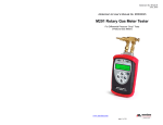
M200 Smart Manometer & M201 Roots Meter Tester
The purpose of this Supplement is to provide corrections, clarifications or
additions to the user information contained in the M2 – Series User Manual
(controlled drawing number 9R000045-A). These corrections, clarifications or
additions relate to the user interface or available sensor ranges or styles only.
Changes as of June 06, 2007
1. Page 4; Backlight Key – delete Red backlight from “…green, red and off.” description. The
“red” position has been eliminated.
2. Page 8; Flow Unit Select – add information on calculating the Flow constant (equation and
example).
Calculate the Flow constant from the following equation:
Fc = Q ÷ DP½
where: Fc = Flow constant
Q = Flow rate from (flow element calculation sheet)
DP = Differential pressure corresponding to Q
Example: If the DP is 25 units when the flow rate is 10,000 units, the Flow constant is
2,000.
3. Page 11; Add clarification note to bottom of “Auto Shut-Off” page to clarify operation when
Data Logging or Leak Test features are used.
The “Auto Shut-Off” timer is suspended during Data Logging and Leak Test sessions to
prevent accidental loss of information. Auto Shut-Off is re-instated after completion of DataLogging or Leak Test sessions.
4. Page 15; Add clarification note to “Data Logging” page for Auto Shut-Off timer operation.
The “Auto Shut-Off” timer is disabled for Data Logging sessions. Be sure to end the session
to re-enable the Auto Shut-Off timer.
5. Page 16; Add clarification note to “Leak Test” page for Auto Shut-Off timer operation.
The “Auto Shut-Off” timer is disabled for Leak Test sessions. Be sure to end the session to
re-enable the Auto Shut-Off timer.
6. Page 23; replace the Specifications Table with the following one (added 30 and 300 psig
ranges, deleted 900 mmHg range, converted 2000 mmHg range to 38 psia, added ±0.1%
FS accuracy for 28 inH2O range, deleted information for “Wet/Wet,” “DI” and “O-RING
Material…”):
1
May 29, 2007
M2 –Series User Manual Supplement
Reference M2 Manual Dwg. No. 9R000045-A
M200 Smart Manometer & M201 Roots Meter Tester
Type and Range and Display Resolution:
Differential Non-Isolated Types:
28 inH2O (1 psid) – XX.YYY
200 inH2O (7.21 psid) – XXX.YY
2000 inH2O (72.1 psid) – XXXX.Y
Gauge Isolated Types:
15 psig – XX.YYY
30 psig – XX.YYY
200 psig – XXX.YY
300 psig – XXX.YY
2000 psig – XXXX.Y
Absolute Isolated Types:
900 mmHg (17 psia) – XXX.YY
38 psia (2000 mmHg) – XX.XXY
Wet/Wet Types:
1 and 5 psid – X.YYYY
15, 30 and 50 psid – XX.YYY
100, 300 and 500 psid – XXX.YY
Accuracy:
±0.025% of Full Scale or ±0.05% of Full Scale
(±0.1% of Full Scale for 28 inH2O Differential range)
Includes the combined effects of temperature, linearity,
repeatability, hysteresis and resolution.
Warm up time = 5 minutes.
Unit should be zeroed at working ambient temperature
before use.
Temperature:
Storage = -40°C to +60°C (-40°F to +140°F)
Operating = -5°C to +50°C (23°F to +122°F)
Media Compatibility:
PORTS:
DN: Differential pressure non-isolated sensors for use with
clean, dry, non-corrosive gases only.
DI, GI , AI: Differential, Gauge, or Absolute pressure sensors
for use with gases and liquids compatible with 316L SS
and O-ring material (DI wet/wet differential sensors only)
O-RING Material (for DI sensors only):
Viton (standard)
Buna-N, Neoprene or Ethylene-Propylene(available options)
Pressure Limits:
2 × range on DN units when pressurized on high side only.
150 PSI (10.5 Kg/cm²) static when applied to both sides of
sensor simultaneously
Connection:
1/8” female NPT, 316L SS. P1 is the high pressure
connection and P2 is the low pressure connection.
Differential port shown below.
User must use a wrench on the pressure manifold when
installing user’s 1/8” NPT fitting. Do not tighten the
fitting without using a wrench on the pressure
manifold. Failure to use a wrench on the manifold will
damage the plastic enclosure and void warranty No
torque should be applied to the manifold with respect
to plastic enclosure.
2
May 29, 2007
M2 –Series User Manual Supplement
Reference M2 Manual Dwg. No. 9R000045-A
M200 Smart Manometer & M201 Roots Meter Tester
Battery Type:
4 each AA alkaline batteries.
IMPORTANT!!! ATEX certified models require the use
of approved batteries only to maintain the ATEX
certification. Refer to Dwg. No. 9R000056 “M2
Intrinsically Safe Control Document” for a list of
batteries approved for hazardous atmospheres. A copy of
this drawing accompanies each unit shipped.
Remove and / or replace batteries in non-hazardous
areas only.
Battery Operation:
>100 hours continuous use, 1 year shelf life, auto power off
programmable at Disabled, 10, 20, 30, 60 or 90 minutes
Enclosure:
(6.9” × 3.8” × 2.3”) Polycarbonate, Permanently Static
Dissipative, ESD Protection
Enclosure with Boot:
(7.2” × 4.2” × 2.5”)
7. Page 28; Disregard graphics for “DI,” “DI w/ FP” and the “Notes: FP…” information. These
are not yet available.
3
May 29, 2007


