1
© Copyright 2003
Roper Scientific, Inc.
3440 East Britannia Drive
Tucson, Arizona 85706
Tel: 800.874.9789/520.889.9933
Fax: 520.295.0299
All rights reserved. No part of this publication may be reproduced by any means without the written
permission of Roper Scientific, Inc.
Printed in the United States of America.
Acrobat and Reader are registered trademarks of Adobe Systems Incorporated in the United States and/or
other countries.
Mac and Macintosh are trademarks of Apple Computer, Inc., registered in the U.S. and other countries.
Nikon is a registered trademark of Nikon Corporation.
PPD is a trademark and Metachrome, PVCAM, and Quantix are registered trademarks of Photometrics Ltd.
RS Image is a trademark and Photometrics is a registered trademark of Roper Scientific, Inc.
Windows and Windows NT are registered trademarks of Microsoft Corporation in the United States and/or
other countries.
Other brand and product names are the trademarks or registered trademarks of their respective owners and
manufacturers.
The information in this publication is believed to be accurate as of the publication release date. However,
Roper Scientific does not assume any responsibility for any consequences including any damages resulting
from the use thereof. The information contained herein is subject to change without notice. Revision of this
publication may be issued to incorporate such change.
Warning: This is a Class A product. In a domestic environment this product may cause radio interference in which case
the user may be required to take adequate measures.
57-053-001 Rev B3
LIMITED WARRANTY — Roper Scientific Analytical Instrumentation
Roper Scientific, Inc. (“Roper Scientific,” us,” “we,” “our”) makes the following limited warranties. These
limited warranties extend to the original purchaser (“You”, “you”) only and no other purchaser or transferee.
We have complete control over all warranties and may alter or terminate any or all warranties at any time we
deem necessary.
Basic Limited One (1) Year Warranty
Roper Scientific warrants this product against substantial defects in materials and / or workmanship for a
period of up to one (1) year after shipment. During this period, Roper Scientific will repair the product or, at
its sole option, repair or replace any defective part without charge to you. You must deliver the entire product
to the Roper Scientific factory or, at our option, to a factory-authorized service center. You are responsible for
the shipping costs to return the product. International customers should contact their local Roper Scientific
authorized representative/distributor for repair information and assistance, or visit our technical support
page at www.roperscientific.com.
Limited One (1) Year Warranty on Refurbished or Discontinued Products
Roper Scientific warrants, with the exception of the CCD imaging device (which carries NO WARRANTIES
EXPRESS OR IMPLIED), this product against defects in materials or workmanship for a period of up to one
(1) year after shipment. During this period, Roper Scientific will repair or replace, at its sole option, any
defective parts, without charge to you. You must deliver the entire product to the Roper Scientific factory or,
at our option, a factory-authorized service center. You are responsible for the shipping costs to return the
product to Roper Scientific. International customers should contact their local Roper Scientific
representative/distributor for repair information and assistance or visit our technical support page at
www.roperscientific.com.
Normal Wear Item Disclaimer
Roper Scientific does not warrant certain items against defect due to normal wear and tear. These items
include internal and external shutters, cables, and connectors. These items carry no warranty, expressed or implied.
VersArray (XP) Vacuum Chamber Limited Lifetime Warranty
Roper Scientific warrants that the cooling performance of the system will meet our specifications over the
lifetime of the VersArray (XP) detector or Roper Scientific will, at its sole option, repair or replace any vacuum
chamber components necessary to restore the cooling performance back to the original specifications at no
cost to the original purchaser. Any failure to “cool to spec” beyond our Basic (1) year limited warranty from date of
shipment, due to a non-vacuum-related component failure (e.g., any components that are electrical/electronic) is NOT
covered and carries NO WARRANTIES EXPRESSED OR IMPLIED. Responsibility for shipping charges is as
described above under our Basic Limited One (1) Year Warranty.
Sealed Chamber Integrity Limited 24 Month Warranty
Roper Scientific warrants the sealed chamber integrity of all our products for a period of twenty-four (24)
months after shipment. If, at anytime within twenty-four (24) months from the date of delivery, the detector
should experience a sealed chamber failure, all parts and labor needed to restore the chamber seal will be
covered by us. Open chamber products carry NO WARRANTY TO THE CCD IMAGING DEVICE, EXPRESSED
OR IMPLIED. Responsibility for shipping charges is as described above under our Basic Limited One (1) Year
Warranty.
Vacuum Integrity Limited 24 Month Warranty
Roper Scientific warrants the vacuum integrity of all our products for a period of up to twenty-four (24)
months from the date of shipment. We warrant that the detector head will maintain the factory-set operating
temperature without the requirement for customer pumping. Should the detector experience a Vacuum
Integrity failure at anytime within twenty-four (24) months from the date of delivery all parts and labor
needed to restore the vacuum integrity will be covered by us. Responsibility for shipping charges is as
described above under our Basic Limited One (1) Year Warranty.
i
Image Intensifier Detector Limited One Year Warranty
All image intensifier products are inherently susceptible to Phosphor and/or Photocathode burn (physical
damage) when exposed to high intensity light. Roper Scientific warrants, with the exception of image
intensifier products that are found to have Phosphor and/or Photocathode burn damage (which carry NO
WARRANTIES EXPRESSED OR IMPLIED), all image intensifier products for a period of one (1) year after
shipment. See additional Limited One (1) year Warranty terms and conditions above, which apply to this warranty.
Responsibility for shipping charges is as described above under our Basic Limited One (1) Year Warranty.
X-Ray Detector Limited One Year Warranty
Roper Scientific warrants, with the exception of CCD imaging device and fiber optic assembly damage due to
X-rays (which carry NO WARRANTIES EXPRESSED OR IMPLIED), all X-ray products for one (1) year after
shipment. See additional Basic Limited One (1) year Warranty terms and conditions above, which apply to this
warranty. Responsibility for shipping charges is as described above under our Basic Limited One (1) Year
Warranty.
Software Limited Warranty
Roper Scientific warrants all of our manufactured software discs to be free from substantial defects in
materials and / or workmanship under normal use for a period of one (1) year from shipment. Roper
Scientific does not warrant that the function of the software will meet your requirements or that operation will
be uninterrupted or error free. You assume responsibility for selecting the software to achieve your intended
results and for the use and results obtained from the software. In addition, during the one (1) year limited
warranty. The original purchaser is entitled to receive free version upgrades. Version upgrades supplied free
of charge will be in the form of a download from the Internet. Those customers who do not have access to the
Internet may obtain the version upgrades on a CD-ROM from our factory for an incidental shipping and
handling charge. See Item 12 in the following section of this warranty ("Your Responsibility") for more information.
Owner's Manual and Troubleshooting
You should read the owner’s manual thoroughly before operating this product. In the unlikely event that you
should encounter difficulty operating this product, the owner’s manual should be consulted before contacting
the Roper Scientific technical support staff or authorized service representative for assistance. If you have
consulted the owner's manual and the problem still persists, please contact the Roper Scientific technical
support staff or our authorized service representative. See Item 12 in the following section of this warranty ("Your
Responsibility") for more information.
Your Responsibility
The above Limited Warranties are subject to the following terms and conditions:
ii
1.
You must retain your bill of sale (invoice) and present it upon request for service and repairs or
provide other proof of purchase satisfactory to Roper Scientific.
2.
You must notify the Roper Scientific factory service center within (30) days after you have taken
delivery of a product or part that you believe to be defective. With the exception of customers who
claim a “technical issue” with the operation of the product or part, all invoices must be paid in full in
accordance with the terms of sale. Failure to pay invoices when due may result in the interruption
and/or cancellation of your one (1) year limited warranty and/or any other warranty, expressed or
implied.
3.
All warranty service must be made by the Roper Scientific factory or, at our option, an authorized
service center.
4.
Before products or parts can be returned for service you must contact the Roper Scientific factory and
receive a return authorization number (RMA). Products or parts returned for service without a return
authorization evidenced by an RMA will be sent back freight collect.
5.
These warranties are effective only if purchased from the Roper Scientific factory or one of our
authorized manufacturer's representatives or distributors.
Quantix User Manual
6.
Unless specified in the original purchase agreement, Roper Scientific is not responsible for installation,
setup, or disassembly at the customer’s location.
7.
Warranties extend only to defects in materials or workmanship as limited above and do not extend to
any product or part which has:
•
been lost or discarded by you;
•
been damaged as a result of misuse, improper installation, faulty or inadequate maintenance or
failure to follow instructions furnished by us;
•
had serial numbers removed, altered, defaced, or rendered illegible;
•
been subjected to improper or unauthorized repair; or
•
been damaged due to fire, flood, radiation, or other “acts of God” or other contingencies beyond
the control of Roper Scientific.
8.
After the warranty period has expired, you may contact the Roper Scientific factory or a Roper
Scientific-authorized representative for repair information and/or extended warranty plans.
9.
Physically damaged units or units that have been modified are not acceptable for repair in or out of
warranty and will be returned as received.
10. All warranties implied by state law or non-U.S. laws, including the implied warranties of
merchantability and fitness for a particular purpose, are expressly limited to the duration of the
limited warranties set forth above. With the exception of any warranties implied by state law or nonU.S. laws, as hereby limited, the forgoing warranty is exclusive and in lieu of all other warranties,
guarantees, agreements, and similar obligations of manufacturer or seller with respect to the repair or
replacement of any parts. In no event shall Roper Scientific’s liability exceed the cost of the repair or
replacement of the defective product or part.
11. This limited warranty gives you specific legal rights and you may also have other rights that may vary
from state to state and from country to country. Some states and countries do not allow limitations on
how long an implied warranty lasts, when an action may be brought, or the exclusion or limitation of
incidental or consequential damages, so the above provisions may not apply to you.
12. When contacting us for technical support or service assistance, please refer to the Roper Scientific
factory of purchase, contact your authorized Roper Scientific representative or reseller, or visit our
technical support page at www.roperscientific.com.
iii
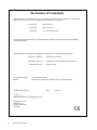
Declaration of Conformity
Roper Scientific, Inc. declares that the equipment described in this document is in conformance
with the requirements of the European Council Directives, listed below:
89/336/EEC
EMC Directive
93/68/EEC
EMC Directive
73/23/EEC
Low Voltage Directive
on the approximation of the laws of Member States relating to Electromagnetic Compatibility
and Product Safety.
This declaration is based upon compliance of the product to the following standards:
EN 55022, CISPR 22
RF Emissions Control
EN 50082-1, IEC 801
Immunity to Electromagnetic Disturbances
EN 60950, IEC 950
Product Description:
Model:
CCD Camera System
Quantix Air-Cooled and Liquid-Cooled Camera Systems
Authorized Signature
Wilhelm Pfanhauser, Managing Director
Photometrics, Ltd.
Sollner Str. 61
D-81479 München
Germany
iv
Quantix User Manual
Product Safety
Date
9/27/96
Table of Contents
Chapter 1. Introduction
Quantix System Components..................................................................................................1
Standard Components ......................................................................................................1
Optional System Hardware..............................................................................................1
About this Manual ....................................................................................................................2
Environmental Requirements .................................................................................................2
Storage Requirements...............................................................................................................2
Precautions.................................................................................................................................2
Camera ................................................................................................................................2
Optional LCU .....................................................................................................................3
Repairs........................................................................................................................................3
Cleaning .....................................................................................................................................3
Roper Scientific Customer Service..........................................................................................4
Chapter 2. System Installation
Introduction ...............................................................................................................................5
Software Compatibility Requirements...................................................................................5
Host Computer Requirements ................................................................................................5
Multiple Cameras......................................................................................................................6
Software Installation.................................................................................................................6
Installing the PCI Card.............................................................................................................7
Connecting the Data Cable ......................................................................................................7
Connecting the Power Brick ....................................................................................................8
Connecting the Optional Liquid Circulation Unit................................................................9
Connecting to Other Equipment...........................................................................................10
Lenses ................................................................................................................................10
Scientific Instruments ......................................................................................................11
Trigger Equipment ..........................................................................................................11
Quantix Camera Stand ....................................................................................................11
Tripod Camera Stand ......................................................................................................12
Focusing Your Camera...........................................................................................................12
Chapter 3. LCU Maintenance
Precautions...............................................................................................................................13
Disconnecting the Coolant Connectors................................................................................13
Refilling the Reservoir............................................................................................................14
Removing Air Bubbles ...........................................................................................................15
Attaching the Coolant Connectors .......................................................................................15
Changing Line Entry Module Fuses and Voltages.............................................................16
Chapter 4. Component Descriptions
Camera .....................................................................................................................................17
CCD ...................................................................................................................................17
Dark Charge Reduction Modes......................................................................................17
Metachrome® II.................................................................................................................17
Certificate of Performance ..............................................................................................18
CCD Chamber ..................................................................................................................18
Window.............................................................................................................................18
Thermoelectric Cooler .....................................................................................................18
v
Shutter ...............................................................................................................................18
Electronics.........................................................................................................................19
Connectors ........................................................................................................................20
Quantix Stand Mount......................................................................................................21
Lenses ................................................................................................................................21
Tripod Mount ...................................................................................................................21
Power Brick..............................................................................................................................22
Liquid Circulation Unit..........................................................................................................22
Chapter 5. Troubleshooting
System Does Not Boot Normally..........................................................................................23
New Hardware Found Dialog Box Does Not Appear (Windows 95/98/2000/ME/XP) .. 24
Image is Smeared or Camera Will Not Reach Saturation..................................................24
Images Not Displayed Properly............................................................................................24
Camera Does Not Focus.........................................................................................................24
Camera Does Not Respond to Light.....................................................................................25
Replacing Camera Shutter ..............................................................................................25
Camera Not Cooling...............................................................................................................27
PVCAM Error Message Appears..........................................................................................27
Lengthy Pauses During Imaging ..........................................................................................27
Changing LCU Line Entry Module Fuses and Voltage .....................................................28
Chapter 6. Specifications
Camera (General) ....................................................................................................................31
Shutter ......................................................................................................................................31
F-Mount Camera .....................................................................................................................32
F-Mount Air-Cooled Camera .........................................................................................33
F-Mount Liquid-Cooled Camera ...................................................................................34
F-Mount Camera (KAF 6303E & TH 7899M) ......................................................................35
F-Mount Air-Cooled Camera (KAF 6303E) ..................................................................36
F-Mount Liquid-Cooled Camera (KAF 6303E , TH 7899M).......................................37
C-Mount Camera ....................................................................................................................38
C-Mount Air-Cooled Camera.........................................................................................39
C-Mount Liquid-Cooled Camera...................................................................................40
Power Brick..............................................................................................................................41
Liquid Circulation Unit..........................................................................................................42
Connector/Cable Pinouts ......................................................................................................43
Input/Output Status Connector Pinout .......................................................................43
Trigger Connector............................................................................................................44
Shutter Status Connector ................................................................................................44
Power Connector Pinout.................................................................................................45
Data Cable Pinout ............................................................................................................46
KAF 1401E CCD ......................................................................................................................47
KAF 1602E CCD ......................................................................................................................49
KAF 6303E CCD ......................................................................................................................51
CCD57-10 .................................................................................................................................53
TH 7899M CCD .......................................................................................................................55
Appendix A. Trigger Modes
Trigger-First Mode..................................................................................................................57
Strobe Mode.............................................................................................................................57
Bulb Mode................................................................................................................................57
Index....................................................................................................... 59
vi
Quantix User Manual
Chapter 1.
Introduction
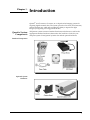
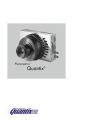
Quantix® is an F-mount or C-mount, air- or liquid-cooled imaging system for
acquiring digital scientific data. The system provides a fast focus, fast frame rate,
and fast readout rate, while still providing the ability to acquire low-light
images by integrating over long periods of time.
Quantix System
Components
All Quantix systems consist of standard hardware and software as well as the
appropriate interface hardware (discussed in the Installation Guide) for your
computer system. Some Quantix systems also include optional hardware.
Standard Components
Optional System
Hardware
1
About this
Manual
The Quantix User Manual is divided into six chapters. It is suggested that you
read the entire manual before operating the camera to ensure proper usage. The
chapters that follow this introduction are:
•
System Installation — Instructions for installing the camera system’s
hardware and software
•
LCU Maintenance — Instructions for maintaining the liquid circulation
unit
•
Component Descriptions — Functional description of each camera
system component
•
Troubleshooting — Answers to camera hardware problems
•
Specifications — Specifications for each camera system component
Note: To install a new camera, follow the instructions in the System Installation chapter
of this User Manual.
Environmental
Requirements
The Quantix camera system and its optional liquid circulation unit should be
operated in a clean, dry environment. The camera system requires that an easily
accessible electrical outlet be available near the equipment.
The camera system’s ambient operating temperature is 0°C to 30°C with a
relative humidity of 0%–80% noncondensing.
Storage
Requirements
Precautions
Camera
2
Quantix User Manual
Store the Quantix camera system and the LCU in their original containers. To
protect the system from excessive heat, cold, and moisture, store at an ambient
temperature between -20°C and 60°C with a relative humidity of 0%–90%
noncondensing.
The charge-coupled device (CCD) and other system electronics are extremely
sensitive to electrostatic discharge (ESD) and the optional liquid circulation unit
requires periodic maintenance.
To avoid permanently damaging the system, please observe the following
precautions:
•
If you are using high-voltage equipment (such as an arc lamp) with your
camera system, be sure to turn the camera power on last and power the
camera off first.
•
Always switch off and unplug the power brick before changing your
system configuration in any way.
•
Use caution when triggering high-current switching devices (such as an
arc lamp) near your system. The CCD can be permanently damaged by
transient voltage spikes. If electrically noisy devices are present, an
isolated, conditioned power line or dedicated isolation transformer is
highly recommended.
•
Never connect or disconnect any cable while the camera system is
powered on. Reconnecting a charged cable may damage the CCD.
Optional LCU
Repairs
Cleaning
•
Never impede airflow through the equipment by obstructing the air
vents.
•
If your system is equipped with an LCU, power the LCU on before
powering on the camera.
To prevent damage to the LCU:
•
Keep the seals lubricated by running the LCU 45 minutes at least once a
month.
•
Always keep the pump primed by operating LCU in the upright
position.
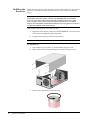
•
When disconnecting the coolant hoses from the camera, it is important
to prevent any coolant from spilling into the camera. When
disconnecting the hoses, hold the camera over an absorbent material,
such as paper towels, with the connectors facing down.
•
Never impede airflow through the LCU by obstructing the air vents.
Other than repairs described in this manual, all repairs must be done by Roper
Scientific. Should your system hardware need repair, contact Roper Scientific
Customer Service. Please save the original packing materials so you can safely
ship the camera system to another location or return it for repairs if necessary.
Clean exterior surfaces of the camera system with a dry, lint-free cloth. To
remove stains, contact Roper Scientific Customer Service.
Chapter 1. Introduction
3
Roper Scientific
Customer Service
If you have any questions about your camera system, contact Roper Scientific
Customer Service. When you call, please have your Roper Scientific job number
or equipment serial numbers available.
•
•
•
•
Tel:
Fax:
E-mail:
Mail:
800. 874.9789/ 520.889.9933 between 8:00 am and 5:00 pm MST
520.295.0299
[email protected]
Roper Scientific
3440 East Britannia Drive
Tucson, Arizona 85706
In Europe, you can reach Customer Service at:
BENELUX
•
•
•
•
Tel:
Fax:
E-mail:
Mail:
31.347.324989
31.347.324979
[email protected]
Roper Scientific, BV
Ir. D.S. Tuijnmanweg 10
4131 PN VIANEN, Netherlands
FRANCE
•
•
•
•
Tel:
Fax:
E-mail:
Mail:
33.160.86.03.65
33.160.86.07.09
[email protected]
Roper Scientific, SARL
Z.I. Petite Montagne Sud
4, rue de l'Oisans - C.E. 1702
91017 Evry Cedex, France
GERMANY
•
•
•
•
Tel:
Fax:
E-mail:
Mail:
49.89.660.779.3
49.89.660.779.50
[email protected]
Roper Scientific, GmbH
Rosenheimer Landstr. 87
D-85521 Ottobrunn, Germany
In Japan, you can reach Customer Service at:
•
•
•
•
Tel:
Fax:
E-mail:
Mail:
81.43.274.8022
81.43.274.8023
[email protected]
Nipon Roper, K.K.
D-10E 1-3 Nakase,
Mihama-ku, Chiba-shi
Japan 261-8501
General product information and answers to some customer service questions can
be found on our website: http://www.roperscientific.com
4
Quantix User Manual
Chapter 2.
System Installation
Carefully review the Precautions section on page 2 before performing any of the
procedures outlined here. Again, use only a Quantix cable and a Quantix PCI card with
your Quantix camera. Using a different cable or PCI card may result in permanent
damage to your system.
Introduction
Your Quantix camera system has the following hardware components:
•
Camera Head
•
PCI Card
•
Data Cable
•
Power Brick
•
Power Cord
•
Optional LCU
Quantix system components are linked by the data cable and controlled by your
host computer system via the application software. Power to the camera is
supplied by the power brick. All of these hardware and software components
should be included with your shipment. Refer to the information and figures in
System Components on page 1.
The CCD you selected is installed in your camera.
Keep all the original packing materials so you can safely ship the Quantix
system to another location or return it for service if necessary.
If you have any difficulty with any step of the instructions, call Roper Scientific
Customer Service.
Software
Compatibility
Requirements
Host Computer
Requirements
The Quantix package includes the RS Image™ capture software program
designed for use with your Quantix camera.
All other imaging software must also be PVCAM® -compatible. For full access to
imaging software functions, PVCAM must be version 2.5.2 or higher.
The host computer for your Quantix camera must have the following:
•
Windows® 95, Windows® 98, Windows® ME, Windows NT®,
Windows® XP, or Windows® 2000 operating system
•
200 MHz Pentium® II (or greater)
•
64 MB RAM (or greater)
•
CD-ROM drive
•
At least one unused PCI card slot
•
16-bit color display (or greater)
*To store images to a local hard disk, up to 8 MB of free disk space is needed per file.
5
If you are a Mac® user, the host computer for your Quantix camera must have
the following:
•
Macintosh® OS 8.X, OS 9.X, or OS X
•
64 MB RAM (or greater)
•
CD-ROM drive
•
At least one unused PCI card slot
•
Video adapter that supports 24-bit color (millions of colors)
*To store images to a local hard disk, up to 8 MB of free disk space is needed per file.
Multiple Cameras
PVCAM supports multiple open cameras. In order to use this function, your
imaging software must also support it. The RS Image capture software program
included with your system supports multiple cameras, as do many other imaging
packages.
If your imaging software supports multiple cameras, there must be a separate
PCI card for each camera. Multiple cameras can only be open simultaneously if
all use PCI interfaces.
Software
Installation
An Installation Guide appropriate to your system is included as an insert in the
CD-ROM case. This guide provides step-by-step instructions for installing the
camera interface software and the application software for Windows-based and
Macintosh-based PCs. Additional instructions are included for installing a PCI
card in your computer and capturing images.
The CD-ROM contains the following files.
6
Quantix User Manual
•
Readme text files — these files contain the latest information on the
software installations and should be read before you run the
PVCAMSetup program.
•
PVCAMSetup software program — this software installs the camera
interface software.
•
RSImageSetup software program — this software installs the RS Image
application program.
•
MacOS directory — this directory contains the files required for
installing on a Macintosh computer.
•
Acrobat directory — this directory contains subdirectories containing
installation programs for Acrobat® Reader®.
•
Manuals directory — this directory contains user manuals in PDF
format.
Installing the
PCI Card
You will be using a Quantix PCI card to allow the camera to communicate with
your computer.
Refer to the Readme text files on the CD-ROM and to the Installation Guide
supplied with the CD-ROM before installing the PCI card. Please follow the
instructions when installing the card.
After installing the PCI card, go to Connecting the Data Cable.
The Data cable connects your Quantix camera to the PCI card installed in your
computer.
Connecting the
Data Cable
Data Cable
To connect your Quantix camera:
1.
Connect either end of the Data cable to the AIA port on the camera (see the
figure below).
2.
Connect the other end of the Data cable to the PCI card in the host
computer.
Chapter 2. System Installation
7
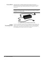
Connecting the
Power Brick
The power brick is a switched supply that is shipped with a power cord.
Caution: Connecting or removing a live power cable to or from the Quantix camera can
damage the camera's electronic components. Do not attach or remove any cables while
the power brick is switched on (On = |, Off = 0) and plugged into an electrical outlet.
To connect the power brick to the camera:
Power Brick Cable with 15-Pin, D Connector
1.
Connect the power brick cable's 15-pin, D connector to the power port
on the back of the camera. Secure by tightening the connector screws.
Do not extend this cable.
2.
With the power brick switched off and the power cord unplugged from
an electrical outlet, connect the power cord to the power brick (and later
to an electrical outlet).
Instructions for powering on and powering off the camera system are provided
in the Installation Guide supplied with the CD-ROM. After 15 to 30 minutes of
operation, the camera will reach its default operating temperature.
8
Quantix User Manual
Connecting the
Optional Liquid
Circulation Unit
The liquid-cooled camera can be operated with or without the LCU. If you
choose to operate the camera without the LCU, the default operating
specifications will be slightly different. For operating specifications, see
Chapter 6. Specifications.
In order to operate properly, the reservoir in the LCU must be at least 3/4 full:
•
If you are installing a newly shipped LCU, the reservoir is filled with the
proper amount of coolant. Follow connection instructions below.
•
If you are not installing a newly shipped LCU, check to see if either of
the following conditions apply:
•
Low coolant level because you have lost coolant while
disconnecting and reconnecting the hoses.
•
You have not checked the coolant level in 3 months.
If either condition applies, see Refilling the Reservoir on page 14 to check the
coolant level in the reservoir.
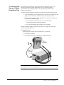
To connect the LCU:
With the power switch in the off position (Off = 0), connect:
•
LCU hoses to camera
•
LCU power cord to LCU (and later to an electrical outlet)
Caution: Do not allow the reservoir to drain below half full. To keep the pump primed,
always operate the LCU in the upright position.
Chapter 2. System Installation
9
When disconnecting the LCU from the camera, it is important to keep any
coolant from spilling into the camera. Make sure to see Disconnecting the Coolant
Connectors on page 13 for instructions on disconnecting the LCU.
You have completed installing the LCU.
If, during operation, the camera does not appear to be cooling properly:
•
Check to see if coolant is moving through the liquid circulation unit.
•
Check the fluid level in the reservoir. To add more coolant to the
reservoir, see Refilling the Reservoir on page 14.
•
If the coolant is clouded with many tiny bubbles, your coolant level may
be low. See Removing Air Bubbles on page 15.
•
Check the hose and power cord connections.
•
Check the LCU line entry module fuse. For instructions on accessing
and changing the fuse, see Changing LCU Line Entry Module Fuses and
Voltages on page 28.
If the camera still does not cool, contact Roper Scientific Customer Service.
If you are connecting other equipment such as lenses, scientific equipment,
triggering equipment, peripherals, or camera stands go to the next section,
Connecting to Other Equipment.
Connecting to
Other Equipment
The camera can be operated in any orientation, allowing it to be adapted to
many configurations. The F-mount configuration has a Nikon® bayonet mount
with a standard F-mount flange focal distance. The C-mount configuration is a
standard threaded video mount with a standard C-mount flange focal distance.
The camera has mounts that accommodate a standard tripod mounting bolt.
Note: When mounting the camera on an instrument, do not block any air vents. Blocking
the airflow through the camera can damage the CCD. Make sure to allow at least
one inch of air space in front of all vents.
Lenses
10
Quantix User Manual
With the F-mount camera, you can install any lens that is compatible with a
standard Nikon bayonet mount. With the C-mount camera, you can install any
lens that is compatible with a standard threaded video mount as long as the
objective does not extend farther than .27 inches behind the flange of the lens. A
C-mount lens with optics that protrude a long distance into the camera may
interfere with the shutter blades. For specifications on calculating acceptable
flange focal distances, see F-Mount Camera on page 32 or C-Mount Camera on
page 38. Photometrics offers compatible C- and F-mount lenses.
To install a lens, remove the camera aperture cover. Insert the lens into the lens
mount. C-mount lenses screw in. F-mount lenses should be turned until they
lock in place.
Scientific Instruments
The F-mount camera can be mounted to any instrument that is compatible with
a standard Nikon bayonet mount. The C-mount camera can be mounted to any
instrument that is compatible with a standard threaded video mount. If you
need to adjust your Quantix focal distance for parfocal adjustment, use standard
optical shims. (Shims are precision washers that are placed over the threading of
the C-mount of the instrument in order to increase the distance between the
CCD plane and the instrument.) If your instrument requires a mount adapter,
contact your instrument supplier.
Trigger Equipment
You can connect the camera to trigger equipment through the I/O Status,
Trigger, or Shutter Status connectors on the camera. For pin-out specifications
for each connector, see Connector/Cable Pinouts starting on page 43.
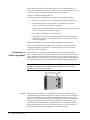
Quantix Camera Stand
Roper Scientific offers an optional Quantix camera stand. Since the camera can
be operated in any position, the camera can be attached to the stand with the
connectors facing up or to either side. To install the camera stand, thread the
two bolts into the camera frontplate.
Chapter 2. System Installation
11
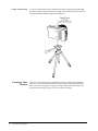
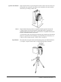
Tripod Camera Stand
Focusing Your
Camera
12
Quantix User Manual
If you use a tripod camera stand, make sure the stand is large enough and stable
enough to securely support the camera’s weight. The camera has two mounts that
will accommodate a standard tripod mounting bolt.
After you have finished system installation and have started the application
software, you can focus the camera for the best image. Using the instructions
from your software program, bring your software into focus loop mode. For
instructions on using RS Image to focus, see the on-line help.
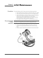
Chapter 3
Precautions
Disconnecting the
Coolant
Connectors
LCU Maintenance
To prevent damage to the LCU please observe the following precautions:
•
Keep seals lubricated by running LCU 45 minutes at least once a month.
•
Always keep pump primed by operating LCU in the upright position.
•
When disconnecting the coolant hoses from the camera, it is important
to prevent any coolant from spilling into the camera. When
disconnecting the hoses, hold the camera over an absorbent material,
such as paper towels, with the connectors facing down.
•
Never impede airflow through the LCU by obstructing the air vents.
Caution: When disconnecting the coolant hoses, excess coolant will spill from the hoses
and connectors. It is important to prevent coolant from spilling into the camera.
1.
Turn off the LCU power (Off = 0).
2.
To keep excess coolant from spilling into the camera, position the
camera over absorbent material with the coolant connectors facing
down.
3.
Press the connector release tabs and disconnect the hoses from camera.
13
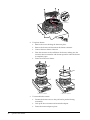
Refilling the
Reservoir
Check the reservoir every three months to see if coolant needs to be added to the
system. (To check the reservoir level, remove the cover as shown on the next
page.)
WARNING: Use only the fluorescent pink coolant mixture supplied by Roper Scientific
(part number 24-071-001), which is a mixture of DOWTHERM SR-1 and de-ionized
water. Use of any other coolant mixture may lead to instrument failure (see Coolant
section on page 1 of the LCU user manual for further explanation). Do not combine
mixtures (see Compatibility with Traditional Ethylene Glycol in Appendix A of the LCU
user manual (57-058-001) for more information).
Add coolant if the reservoir is less than 3/4 full.
•
Required coolant mixture: mixture of DOWTHERM SR-1 and de-ionized
water (mixture supplied by Roper Scientific)
•
Liquid coolant capacity: 27 fluid ounces (800 cc)
Caution: Do not allow the reservoir to drain below 1/2 full.
To refill the LCU:
14
Quantix User Manual
1.
Turn off the LCU power (Off = 0), and disconnect the power cord.
2.
Remove the four screws on the back panel of the LCU. Remove cover.
3.
Remove the cap from the coolant reservoir.
4.
Fill the reservoir to approximately 1/4” from the top with the coolant
mixture supplied by Roper Scientific.
WARNING: Use only the fluorescent pink coolant mixture supplied by Roper
Scientific (part number 24-071-001), which is a mixture of DOWTHERM SR-1
and de-ionized water. Use of any other coolant mixture may lead to instrument
failure (see Coolant section on page 1 of the LCU user manual for further
explanation). Do not combine mixtures (see Compatibility with Traditional
Ethylene Glycol in Appendix A of the LCU user manual (57-058-001) for more
information).
Removing Air
Bubbles
5.
Replace the reservoir cap, LCU cover, and screws.
6.
Reconnect the power cord.
Normally, air bubbles that have formed in the tubing due to low coolant level
will work their way out after the reservoir is filled. However, if the fluid level in
the reservoir has become exceptionally low or if the LCU was operated on a
slanted surface, bubbles may remain in the tubing even after refilling the
reservoir. In order to clear these bubbles, it may be necessary to watch the
coolant flow through the tubing inside the LCU.
•
First fill the reservoir to the proper level and then reinstall the cover
securely on the reservoir.
•
With the LCU connected to a camera head and turned on, look for any
tube inside the LCU that is not completely filled with coolant.
WARNING: Use extreme caution while working inside an operating LCU.
There is a cooling fan that could cause physical injury, and voltages up to 240V,
which could cause electrical shock.
Attaching the
Coolant
Connectors
•
If you find a tube with air in it, lift the LCU and tilt and rotate it so the
air bubble works its way back to the reservoir inlet. The goal is to have
the LCU pump air bubbles back into the reservoir. Air always moves up
in relation to fluids, so you should tilt and rotate the LCU so air bubbles
can move up through the liquid. The air bubbles may have to travel all
the way through the tubing and the camera head on their way back to
the reservoir.
•
Keep in mind that the reservoir outlet is at the bottom of the reservoir.
Be sure the reservoir outlet is completely submerged at all times. If you
tilt the LCU so the reservoir outlet is higher than the fluid level, the
pump will introduce more air into the tubing.
•
Coolant will eventually displace all air bubbles in the tubing. Once the
bubbles have been worked out of the tubing, the reservoir may need to
be filled since coolant formerly in the reservoir is now in the tubing in
place of the air bubbles.
See Connecting the Optional Liquid Circulation Unit on page 9.
Chapter 3. LCU Maintenance
15
Changing Line
Entry Module
Fuses and
Voltages
16
Quantix User Manual
The voltage selector card and fuse configuration on the AC line entry module is
set to the correct voltage for your country. If your voltage needs to be changed,
you will need to change the voltage selector card, and you may need to change
the fuse configuration. To change the voltage and the fuse configuration see
Changing LCU Line Entry Module Fuses and Voltages on page 28.
Chapter 4.
Component Descriptions
The Quantix camera system consists of the F-mount or C-mount camera, power
brick, PCI card, and an optional liquid circulation unit.
Quantix C-mount Camera
Camera
CCD
Dark Charge Reduction
Modes
Metachrome® II
The camera body houses the CCD cooling system and the camera electronics.
The CCD is inside a vacuum-sealed chamber. All of the components inside the
camera body are sensitive electronic components and are not user accessible.
Opening the camera body voids the camera warranty.
When you order a Quantix camera, you choose from a range of CCDs that differ
in size and grade. All Quantix CCDs are scientific-grade, grades with fewer
defects than commercial grades. Scientific-grade CCDs image with better
resolution, have low noise so they can detect weak signals, and are linear over
the dynamic range so you can accurately judge intensity differences between
objects.
All Quantix cameras have either Multi-Pinned Phase (MPP) or Advanced
Inverted Mode Operation (AIMO) CCDs. These CCDs are built to have less
thermally generated noise for a given exposure time, a property useful when
trying to detect weak signals.
Metachrome II is a proprietary, optional, permanent CCD coating that is
available on all Quantix CCDs. This coating extends the CCD's sensitivity to
below 200 nm and is transparent from 400 to 1100 nm wavelength light. The
coating requires no maintenance and does not degrade over time.
17
Certificate of
Performance
Each Quantix camera has a Certificate of Performance. This certificate states the
CCD grade that has been designated by the CCD manufacturer. The certificate
also provides the camera performance information needed to effectively
measure photon flux with repeatable, scientific accuracy. A copy of the
information contained in the Performance Certificate is kept on file at Roper
Scientific Customer Service.
CCD Chamber
The vacuum-sealed CCD chamber protects the CCD from contamination as well
as insulating it from the warmer air in the camera body. The low humidity also
reduces the chance of condensation forming on the CCD when the temperature
is lowered. If any gasses are trapped in the vacuum chamber, they are absorbed
by a sieve located inside the chamber.
The vacuum also isolates the window from the cooled CCD. This thermal barrier
keeps the window from cooling below the dew point, thereby preventing
condensation on the window.
Window
The camera has one window in the optical path. The CCD does not have a
window. Compared to a multiple-window design, a single window reduces the
chance of image degradation due to multiple reflections, stray light, and
interference patterns.
The standard Photometrics window is made of fused silica (quartz) with a
broadband antireflective coating. Fused silica has better ultraviolet transmission
than crown glass. The antireflective coating increases the light transmitted
through the window from 92% to 99%, further decreasing light loss.
Optional infrared-blocking (IR) windows are available. The IR window blocks
optical radiation above 650 nm, providing a sharper image.
Thermoelectric Cooler
While the CCD accumulates charge, thermal activity releases electrons,
generating dark current. Cooling the CCD helps enhance the low-light
sensitivity by reducing the thermally generated charge.
Cooled CCD cameras produce less dark current than cameras operating at
ambient temperature. When the ambient temperature is between 0°C and 30°C,
the CCD in the Quantix camera is cooled to a minimum of -25°C for the aircooled cameras and a minimum of -35°C for liquid cooled.
The CCD is cooled by a two- or three-stage Peltier cooler, a thermoelectric cooler
(TEC) that pulls heat away from the CCD and into a heat exchanger. The heat
exchanger transfers the heat into the camera body, where it is passively radiated
to the environment. In certain situations, a separate liquid cooling unit removes
additional heat from the heat exchanger.
Shutter
The camera has a high-speed shutter. For shutter specifications, see Chapter 6,
Specifications.
The shutter is a mechanical component that has a limited life with heavy use.
Instructions for testing and replacing the shutter are in Chapter 5. Troubleshooting.
18
Quantix User Manual
The CCD produces an analog signal. The camera electronics convert the analog
signal into a digital signal, data that can be received by the host computer.
Several factors influence what portion of the analog signal translates into digital
data. One factor is the noise in the camera system. The system noise includes the
thermal noise produced by the camera components and the read noise determined
in part by how far the analog signal must travel. The farther an analog signal has to
travel, the more the signal degrades.
To reduce signal degradation, Quantix has low-noise electronics and primary point
digitization (PPD™). The PPD design positions the analog-to-digital converter
(ADC) as close to the CCD as possible thereby reducing the distance the analog
signal must travel.
Another determining factor is the quality of the signal received by the ADC. If
the ADC receives a high-quality signal, the 12-bit ADC digitizes the analog
signal into 12-bit data. With a lesser quality signal, the ADC produces data with
a lower effective bit depth.
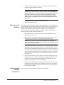
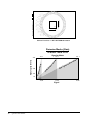
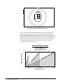
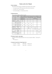
The Quantix camera produces an analog signal that uses the full range of the 12-bit
ADC (up to 4096 gray levels). Through software, the camera can be set to the
detection modes (gains) listed below.
Detection Modes (Gain)
of a KAF 1401E CCD
Signal-to-Noise
100 : 1
200 : 1
283 : 1
e
4095
ng
Ra
ic
yn
am
ivity
1024
ig
h
D
h
Hig
H
Sensit
2048
o
ati
eR
is
No
toaln
g
Si
High
Signal (gray levels)
Electronics
512
10,000
40,000
80,000
Signal
•
Gain 1 — High Signal-to-Noise Mode — when binning, this mode takes
advantage of the output node's maximum full-well capacity, a requirement
when measuring small changes on bright backgrounds. In this mode
(1/2x), the full well of a normal pixel maps to 1/2 of the maximum ADC
count. For a KAF 1401E, with a 2x2 bin, the maximum number of electrons
is ≈80,000.
• Gain 2 — High Dynamic Range Mode — suitable for measuring bright
and dim signals in a field of view. In this mode (1x), the full well of a
normal pixel maps to the maximum ADC count. For a KAF 1401E, the
maximum number of electrons is ≈40,000.
• Gain 3 — High Sensitivity Mode — takes advantage of the CCD’s low
read noise, a requirement for low-light imaging. In this mode (4x), 1/4
full well of a normal pixel maps to the maximum ADC count. For a
KAF 1401E, the maximum number of electrons is ≈10,000.
Data transfers from the CCD to the ADC at the same rate it is transferred from
the ADC to the interface. This rate is the ADC conversion rate. The conversion
rate of your Quantix camera is stated on the Certificate of Performance.
Chapter 4. Component Descriptions
19
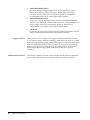
Connectors
Shutter Status
Trigger
Trigger is a BNC connector that gives access to an unfiltered, fast response
trigger. A trigger input allows you to synchronize the camera trigger signal with
external equipment. The signal provided into this input must be clean, or you
may get false triggers. For information on a filtered trigger input, see I/O Status
(below). For specifications on this connector see Trigger Connector on page 44.
AIA
Digital data is transmitted to the host computer through the AIA connector. The
AIA connector is a 68-pin, high-density, I/O connector with a standard AIA
format. The pinout for the parallel cable that mates to the AIA port connector is
located in Data Cable Pinout on page 46.
Power
I/O Status
20
Shutter Status is a BNC connector that gives access to an output signal that
indicates if the shutter is open or in motion. For specifications on this connector
see Shutter Status Connector on page 44.
Quantix User Manual
The power connector is a 15-pin, female, D connector that connects the camera
to the power supply. For power connector pinout specifications see Power
Connector Pinout on page 45.
The Input/Output Status is a 9-pin connector that gives access to a filtered
trigger input, trigger input configuration, and camera status outputs. Pinout
specifications are located in Input/Output Status Connector Pinout on page 43.
Quantix Stand Mount
Roper Scientific offers an optional Quantix camera stand. Since the camera can
be operated in any position, the camera can be attached to the stand with the
connectors up or facing to either side.
Lenses
Roper Scientific sells lenses that are compatible with the Quantix F-mount and
C-mount cameras. The F-mount camera is compatible with any lens that fits a
standard Nikon bayonet mount. The C-mount camera is compatible with any lens
that fits a standard threaded video mount.
A C-mount lens with a long flange focal distance may interfere with the shutter
blades. For specifications for calculating acceptable flange focal distances, see
F-Mount Camera on page 32 and C-Mount Camera on page 35.
Tripod Mount
The camera has two tripod camera stand mounting holes (0.25"-20UNC-2B with a
1/4” depth). A tripod camera stand is available through Roper Scientific.
Chapter 4. Component Descriptions
21
Power Brick
The power brick is a switched, multiple-output-voltage supply with a
detachable power cord. The camera system is powered on (|) and off (0) by a
switch on the supply. More detailed specifications are available in Chapter 5.
Specifications.
Caution: Connecting or removing a live power cable can damage the camera's electronic
components. Do not attach or remove any cables while the power brick is switched on
and plugged into an electrical outlet.
Power Brick with Integrated Cable and Power Cable
Liquid
Circulation Unit
22
Quantix User Manual
The LCU is an optional circulation unit that supplements the air cooling in the
Quantix. The LCU cools the CCD by pumping a mixture of DOWTHERM-SR
ethylene glycol and distilled water through the camera’s heat exchanger. For
LCU specifications see Liquid Circulation Unit on page 42.
Chapter 5.
Troubleshooting
If you have any difficulty while troubleshooting, or do not see your camera system’s
symptoms listed here, contact Roper Scientific Customer Service.
The following issues have corresponding troubleshooting sections in this
chapter.
System Does Not Boot Normally
page 23
New Hardware Found Dialog Box Does Not
Appear (Windows 95/98/2000/ME/XP)
page 24
Image is Smeared or Camera Will Not Reach
Saturation
page 24
Images Not Displayed Properly
page 24
Camera Does Not Respond to Light
page 24
Camera Does Not Focus
page 24
Camera Not Cooling
page 27
PVCAM Error Message Appears
page 27
Lengthy Pauses During Imaging
page 27
Changing LCU Line Entry Module Fuses and
Voltages
page 28
Caution: Do not attach or remove any cables while the camera system is powered on.
System Does
Not Boot
Normally
If your operating system does not boot normally after you have installed a
PCI card, try installing the new card in another open PCI slot. If this does
not work:
1.
Turn off your computer and remove the newly installed PCI card.
2.
Turn your computer back on. If your system boots normally, there is
probably an interrupt conflict between a previously installed expansion
card and the PCI card that you are installing.
3.
If you need assistance resolving the interrupt conflict, contact Roper
Scientific Customer Service.
23
New Hardware
Found Dialog
Box Does Not
Appear
(Windows
95/98/2000/ME/
XP)
Image is
Smeared or
Camera Will
Not Reach
Saturation
If the New Hardware Found dialog box does not appear after installing a
new PCI card to your computer and booting Windows 95/98/2000/ME/XP:
•
Check to make sure that the new PCI card is inserted in a PCI slot
according to your computer manufacturer’s instructions and that the
Quantix system’s CD-ROM is in the host computer’s CD drive.
•
It is possible that there is a conflict between the new PCI card and a
previously installed expansion card. With the computer’s power turned off,
remove any previously installed expansion cards that your system does
not need to function. (If you are unsure which cards can be safely
removed, call Roper Scientific Customer Service.) Then turn your
computer back on and boot Windows 95/98/2000/ME/XP again.
•
If the New Hardware Found dialog box still does not appear,
contact Roper Scientific Customer Service.
If the image is smeared (especially in high-intensity areas of the image) or
the camera will not reach saturation (4095 ADU) and the camera is set to
gain state 1, make sure you use binning factors of at least 2 x 2. Because of
the camera's design, it only saturates at gain state 1 if binning factors of at
least 2 x 2 are defined.
Alternatively, if the light level is low enough, or you are unable to define
binning factors greater than 1 x 1, you could use gain state 2 or gain state 3.
If you have a frame-transfer CCD and you are imaging with the shutter
open continuously, make sure you select Frame Transfer as the Clocking
Mode in your imaging software.
Images Not
Displayed
Properly
If no images appear:
•
Confirm that the red LED on the back of the camera is illuminated,
indicating that the camera is powered on.
•
Confirm that the correct Quantix camera is selected in your imaging
software application.
•
Power off the camera and the host computer and check all system
connections (particularly both ends of the Quantix data cable).
Restart. If no images appear:
•
Confirm that Windows is set for at least 16-bit colors.
•
Confirm that the camera is operational by taking an image with a
standard C-mount lens attached to your Quantix.
Using normal room lighting, place the camera on a table about 3
meters away from an object and acquire an image using your
system’s Brightfield settings.
If the problem persists, contact Roper Scientific Customer Service.
Camera Does
Not Focus
24
Quantix User Manual
If your Quantix camera is not focusing, see the focusing instructions in your
imaging software and lens documentation.
Camera Does
Not Respond
to Light
If your camera has no response to light, a faulty camera shutter may be causing
the problem. To test for a faulty shutter:
1.
Turn on the power to the camera.
2.
As the camera is powering up:
•
If you hear 2 clicks separated by 1 second (shutter opening then
closing), the shutter is working. Call Roper Scientific Customer
Service for further instructions.
•
If you hear 0, 1, or more than 2 clicks, check the voltage between
I/O port pins 3 (exposing) and 9 (ground) while you are powering
up the camera. (See Input/Output Status Connector Pinout on
page 43.)
If the TTL logic level goes from 0 (low) to 1 (high), stays high for 1
second then drops to 0, the shutter signal is working, but the
mechanical shutter is not working. Follow the procedures in
Replacing Camera Shutter below.
If the TTL logic levels do not indicate a working shutter signal, call Roper
Scientific Customer Service.
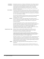
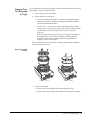
Replacing Camera
Shutter
F-Mount Camera
1.
C-Mount Camera
To access the shutter:
•
Remove the screws holding the mount adapter in place.
•
Remove the mount adapter and slide the canister from the camera.
Chapter 5. Troubleshooting
25
Shutter
Connector
2.
To replace shutter:
•
Remove the screws holding the shutter in place.
•
Remove the shutter and disconnect the shutter connector.
•
Connect the new shutter connector.
•
Place the connector in the well below the shutter, making sure the
connector does not interfere with shutter operation when the shutter
is completely open.
•
Fasten down the new shutter.
F-Mount Camera
3.
26
Quantix User Manual
C-Mount Camera
To reassemble the camera:
•
Position the shutter wires so they will not be pinched during
reassembly.
•
Line up the dots on camera and mount the adapter.
•
Fasten the mount adapter in place.
Camera Not
Cooling
If after 15 minutes of operation the software indicates that the camera has not
reached its operating temperature, make the following checks based on your
system configuration.
Air-Cooled or Liquid-Cooled Camera without LCU:
•
Check the temperature setpoint in the software. Cameras operated
without an LCU should be set to regulate at -25°C.
•
If the camera still does not cool, call Roper Scientific Customer
Service.
Liquid-Cooled Camera with LCU:
PVCAM Error
Message Appears
Lengthy Pauses
During Imaging
•
Check to see if coolant is moving through the unit.
•
If the coolant becomes clouded with many tiny bubbles, your
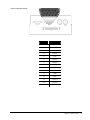
coolant level may be low. Fill the coolant reservoir. See Refilling the
Reservoir on page 14. If bubbles persist, see Removing Air Bubbles on
page 15
•
Check the hose and power cord connections.
•
Check the LCU line entry module fuse. For instructions on accessing
and changing the fuse, see Changing LCU Line Entry Module Fuses
and Voltages on page 28.
•
If the camera still does not cool, call Roper Scientific Customer
Service.
If a PVCAM error message appears, note the message’s number code and
contact Roper Scientific Customer Service.
If you notice lengthy pauses marked by a lot of disk activity while imaging:
•
Close any other programs that may be running.
•
Install more physical memory to your computer system.
Chapter 5. Troubleshooting
27
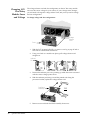
Changing LCU
Line Entry
Module Fuses
and Voltage
The voltage selector card and fuse configuration on the AC line entry module
are set to the correct voltage for your country. If your voltage source changes,
you will need to change the voltage selector card, and you may need to change
the fuse configuration.
To change voltage and fuse configuration:
Voltage
Selector
Card
Cover
1.
With the LCU powered off (Off = 0), remove cover by prying off with a
tool such as a small blade screwdriver.
2.
Using a tool such as a needle nose pliers, pull voltage selector card
straight out.
Indicator
Pin
3.
Position the indicator pin so it is pointing up while the arrow associated
with the correct voltage points down.
4.
With the indicator pin facing out and the printed side facing the
powercord socket, replace the voltage selector card.
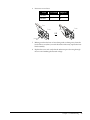
Fuse Block
Assembly
5.
28
Quantix User Manual
OR
Remove screw and slide fuse block assembly from cover.
6.
Insert one or two fuses:
Volts
# of Fuses
Amperes
110-120V
1
2A
220-240V
2
1A
Fuse
Cover
Fuses
Cover
OR
Jumper
Bar
7.
Making sure that the fuse or fuses being used are facing away from the
back of the cover (that is, toward the inside of the unit), replace the fuse
block assembly.
8.
Replace the cover and verify that the indicator pin is showing through
the cover and marking the desired voltage.
Chapter 5. Troubleshooting
29
This page intentionally left blank.
30
Quantix User Manual
Chapter 6.
Specifications
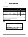
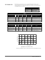
Camera (General)
F-Mount Camera
Specifications
C-Mount Camera
Air Cooled
Liquid Cooled
Air Cooled
Liquid Cooled
≈ 5 lbs
≈ 5 lbs
≈ 5 lbs
≈ 5 lbs
85 Watts
85 Watts
85 Watts
85 Watts
Maximum ambient
operating temperature**
30°C (86°F)
30°C (86°F)
30°C (86°F)
30°C (86°F)
Minimum ambient
operating temperature**
0°C (32°F)
0°C (32°F)
0°C (32°F)
0°C (32°F)
-25°C (-13°F)
-35°C(-31°F)***
w/o LCU -25°C(-13°F)
-25°C (-13°F)
-35°C(-31°F)
w/o LCU -25°C(-13°F)
Weight (without lens)
Power dissipation*
Default operating
temperature**
* During "steady state" (whenever the shutter is not firing: while the shutter is fully opened, closed, or
closing) the power dissipation is 44 Watts.
** Some ambient conditions, combined with an ambient temperature below 0°C or above 30°C, may result
in the camera not stabilizing at the default operating temperature.
***The Quantix:7899 cools to -25°C(-13°F) with liquid. It is not rated for operation without the LCU, and it
is NOT available with air cooling
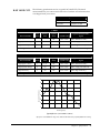
Shutter
Shutter
Type: Aperture (mm)
Uniblitz: 14
Uniblitz: 25
Uniblitz: 35
Open time (msec)
4
6
18
Close time (msec)
8
10
25
Minimum cycle time (fps) *
12
12
6
* Frames per second (fps) while fully opening and closing.
31
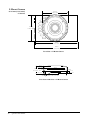
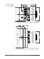
F-Mount Camera
(KAF 1401E, KAF 1602E,
CCD57-10)
5.01 in
(127.2 mm)
5.01 in
(127.2 mm)
7.96 in
(202.2 mm)
8.72 in
(221.5 mm)
Front View — F-Mount Camera
.84 in
(21.3 mm)
Shutter
1.88 in
(47.8 mm) .50 inFront of Chamber
(12.7 mm)
Window Front Surface
.45 in
11.4 mm
CCD
Window Thickness: .125 in (3.2 mm)
Cross Section Side View — F-Mount Camera
32
Quantix User Manual
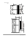
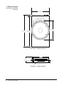
F-Mount Air-Cooled
Camera
5.23 in
(132.8 mm)
2.50 in
(63.6 mm)
5.01 in
(127.2 mm)
4.40 in
(111.8 mm)
2.50 in
(63.6 mm)
TopView — F-Mount Air-Cooled Camera
2.10 in
(53.3 mm)
1.34 in
(34 mm)
3.59 in
(91.2 mm)
8.72 in
(221.5 mm)
4.37 in
(111.0 mm)
7.96 in
(202.2 mm)
3.13 in
79.5 mm
SideView — F-Mount Air-Cooled Camera
Chapter 6. Specifications
33
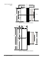
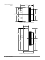
F-Mount Liquid-Cooled
Camera
6.14 in
(156.1 mm)
5.23 in
(132.8 mm)
2.50 in
(63.6 mm)
4.40 in
(111.8 mm)
5.01 in
(127.2 mm)
2.50 in
(63.6 mm)
Top View — F-Mount Liquid-Cooled Camera
.88 in
(22.4 mm)
2.10 in
(53.3 mm)
3.59 in
(91.2 mm)
8.72 in
(221.5 mm)
4.40 in
(111.8 mm)
4.37 in
(111.0 mm)
7.96 in
(202.2 mm)
Side View — F-Mount Liquid-Cooled Camera
34
Quantix User Manual
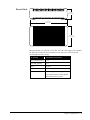
F-Mount Camera
(KAF 6303E, TH 7899M)
5.01 in
(127.2 mm)
5.01 in
(127.2 mm)
7.96 in
(202.2 mm)
8.72 in
(221.5 mm)
Front View — F-Mount Camera (KAF 6303E & TH 7899M)
.84 in
(21.3 mm)
1.88 in
(47.8 mm)
.50 in
(12.7 mm)
Shutter
Window Front Surface
.45 in
(11.4 mm)
Front of Chamber
CCD
Window Thickness: .125 in (3.2 mm)
Cross Section Side View — F-Mount Camera (KAF 6303E &TH 7899M)
Chapter 6. Specifications
35
F-Mount Air-Cooled
Camera
(KAF 6303E)
5.70 in
(144.9 mm)
2.50 in
(63.5 mm)
5.01 in
(127.4 mm)
4.85 in
(123.19 mm)
2.50 in
(63.5 mm)
TopView — F-Mount Air-Cooled Camera (KAF 6303E)
2.10 in
(53.3 mm)
3.59 in
(91.1 mm)
8.72 in
(221.5 mm)
4.850 in
(123.19 mm)
7.96 in
(202.1 mm)
4.37 in
(111 mm)
SideView — F-Mount Air-Cooled Camera (KAF 6303E)
36
Quantix User Manual
F-Mount Liquid-Cooled
Camera
(KAF 6303E , TH 7899M)
6.61 in
(168 mm)
5.70 in
(144.9 mm)
2.50 in
(63.5 mm)
5.01 in
(127.4 mm)
4.85 in
(123.19 mm)
2.50 in
(63.5 mm)
Top View — F-Mount Liquid-Cooled Camera (KAF 6303E & TH 7899M)
.88 in
(22.4 mm)
2.10 in
(53.3 mm)
3.59 in
(91.1 mm)
8.72 in
(221.5 mm)
4.850 in
(123.19 mm)
7.96 in
(202.1 mm)
4.37 in
(111 mm)
Side View — F-Mount Liquid-Cooled Camera (KAF 6303E & TH 7899M)
Chapter 6. Specifications
37
C-Mount Camera
(KAF 1401E, KAF 1602E,
CCD57-10)
5.01 in
(127.2 mm)
5.01 in
(127.2 mm)
8.72 in
7.96 in
(221.5 mm) (202.2 mm)
Front View — C-Mount Camera
.27 in
(7.0 mm)
.70 in
(17.9 mm)
Shutter
Chamber Front Surface
.393 in
(10.0 mm)
Window Front Surface
.37 in
9.5 mm
CCD
Window Thickness: .079 in (2.0 mm)
Focal Plane — C-Mount Camera
38
Quantix User Manual
C-Mount Air-Cooled
Camera
1.98 in
(50.2 mm)
2.50 in
(63.6 mm)
5.01 in
(127.2 mm)
4.25 in
(108.0 mm)
2.50 in
(63.6 mm)
Top View — C-Mount Air-Cooled Camera
2.10 in
(53.3 mm)
1.34 in
(34.0 mm)
3.59 in
(91.2 mm)
7.96 in
(202.2 mm)
4.37 in
(111.0 mm)
8.72 in
(221.5 mm)
4.08 in
(103.6 mm)
Side View — C-Nount Air-Cooled Camera
Chapter 6. Specifications
39
C-Mount Liquid-Cooled
Camera
4.97 in
(126.1 mm)
1.98 in
(50.2 mm)
2.50 in
(63.6 mm)
5.01 in
(127.2 mm)
4.25 in
(108.0 mm)
2.50 in
(63.6 mm)
Top View — C-Mount Liquid-Cooled Camera
2.10 in
(53.3 mm)
8.72 in
(221.5 mm)
3.59 in
(91.2 mm)
7.96 in
(202.2 mm)
4.37 in
(111.0 mm)
4.08 in
(103.6 mm)
Side View — C-Mount Liquid-Cooled Camera
40
Quantix User Manual
Power Brick
2.70 in
(69.0 mm)
10.00 in
(254.0 mm)
5.00 in
(127.0 mm)
The power brick is a +6.5V DC, ±16.5V DC, and +24 V DC supply with 100-240V
AC input at 47-63-60 Hz. The maximum power output is 110 W. The power
brick weighs 3.87 lbs (1.76 kg).
DC Voltage
Maximum Current Draw
+6.5 (system power)
1.9 A
+6.5 (TEC power)
3.4 A
+16.5
150 mA
-16.5
320 mA
+24
1.8 A during shutter firing
50 mA after shutter is fully opened
and when shutter is closed.
Chapter 6. Specifications
41
Liquid
Circulation Unit
10.6 in
269 mm
5.9 in
150 mm
Front View
10.6 in
269 mm
16.1 in
409 mm
Top View
Characteristic
42
Quantix User Manual
Specification
Liquid Coolant Capacity
27 fluid ounces (800 cc)
Required Coolant Mixture
30% DOWTHERM SR-1 and 70% deionized water (supplied by Roper
Scientific)
Flow Rate (approx.)
6 gal/hr (0.38 liters/min)
Weight
27 lbs (12.3 kg)
Voltage Input
100-240 V AC at 50-60 Hz
Power Draw
96 W
Connector/Cable
Pinouts
The Input/Output Status, Trigger, and Shutter Status connectors provide
information about trigger function and shutter status.
5
4
9
3
8
2
7
I/O Status
1
6
Power
Trigger
Shutter
Status
AIA
Input/Output Status
Connector Pinout
All inputs are pulled up to +5V through 10k ohm resistors. Outputs are driven
by a 74HCT244 driver. Inputs must be at least 3.15V for a high and less than
0.9V for a low. The minimum trigger pulse width through this port is 5.5 µsec
(5500 nsec).
The numbers on the trigger connector diagram correspond to the numbers given
to the definition of each of the pins. The I/O connector is a female, Dsubminiature 9-pin connector.
1
WAIT FOR TRIGGER OUTPUT
Active high. A high level on this output indicates that the camera is waiting
for a trigger input.
2
SHUTTER MOVING OUTPUT
Active high. A high level on this output indicates that the shutter is opening
or closing. The output is low when the shutter is completely open or
completely closed. The length of time this signal is held high is specified in
PVCAM? or by the Shutter Open Delay and Shutter Close Delay functions in
the software program.
3
CAMERA EXPOSING OUTPUT
Active high. A high level on this output indicates that the camera is
exposing (integrating).
4
FLASH OUTPUT
This pin is an output that can be controlled in PVCAM with the
FLASH_MODE constant.
5
FACTORY SETUP
This pin is reserved for factory setup.
6
FILTERED TRIGGER INPUT
This input has an RC filter inline to reduce noise on the trigger input. The
input is pulled low to initiate a trigger (default). If nothing is connected to
the input, it is pulled high to prevent the system from getting false triggers.
To change the state of this input see TRIGGER INVERT INPUT (8). (The
inputs are internally pulled up, therefore it is recommended to drive them
with an open collector driver.)
Chapter 6. Specifications
43
Trigger Connector
Shutter Status Connector
44
Quantix User Manual
7
TRIGGER INHIBIT INPUT
This input inhibits all trigger signals. If the input is pulled low, trigger
activity is disabled. By default, the input is pulled high so the trigger
circuitry is enabled. (The inputs are internally pulled up, therefore it is
recommended to drive them with an open collector driver.)
8
TRIGGER INVERT INPUT
Active low. A low on this input inverts the state of FILTERED TRIGGER
INPUT (6) and TRIGGER CONNECTOR (see below), causing a high level to
cause a trigger. (The inputs are internally pulled up, therefore it is
recommended to drive them with an open collector driver.)
9
GROUND
System digital ground. Any external circuitry intended to interface with the
trigger control signals must reference this ground connection.
This input uses a TTL voltage level to trigger the camera. The input is pulled
low to initiate a trigger (default). If nothing is connected to the input, it is pulled
high to prevent the system from getting false triggers. To change the state of this
input see TRIGGER INVERT INPUT (I/O Status 8). (The inputs are internally
pulled up, therefore it is recommended to drive them with an open collector
driver.) The minimum trigger pulse width through this port is 0.5 µsec
(500 nsec).
Active high. A high level on this output indicates that the shutter is completely
open. A low-level output indicates that the shutter is closed or in motion.
Power Connector Pinout
5
4
10
15
3
9
14
I/O Status
2
1
8
13
7
12
6
11
Power
Trigger
Shutter
Status
AIA
Pin #
Signal Name
1
+6.5V
2
+6.5V
3
-16.5V
4
+16.5V
5
+6.5V
6
Ground
7
Ground
8
Ground
9
Ground
10
+6.5V
11
+24V
12
+24V
13
Ground
14
Ground
15
+6.5V
Chapter 6. Specifications
45
Data Cable Pinout
Pin
#
46
Quantix User Manual
Signal
Name
Pin
#
Signal
Name
Pin
#
Signal
Name
1
Ground
24
N/C
47
VD5-
2
Ground
25
FEN+
48
VD4-
3
Ground
26
LEN+
49
VD3-
4
Ground
27
N/C
50
VD2-
5
Ground
28
N/C
51
N/C
6
VD11+
29
PIX+
52
N/C
7
VD10+
30
N/C
53
VD1-
8
VD9+
31
N/C
54
VD0-
9
VD8+
32
N/C
55
N/C
10
VD7+
33
N/C
56
TX-
11
VD6+
34
Ground
57
RX-
12
Ground
35
Ground
58
N/C
13
VD5+
36
VCC
59
FEN-
14
VD4+
37
VCC
60
LEN-
15
VD3+
38
VCC
61
N/C
16
VD2+
39
VCC
62
N/C
17
N/C
40
VD11-
63
PIX-
18
N/C
41
VD10-
64
N/C
19
VD1+
42
VD9-
65
N/C
20
VD0+
43
VD8-
66
N/C
21
N/C
44
VD7-
67
N/C
22
TX+
45
VD6-
68
Ground
23
RX+
46
Ground
KAF 1401E CCD
The following specifications are for a typical KAF 1401E CCD. The actual
measurements for your camera are listed on the Certificate of Performance that
was shipped with your camera.
CCD Specifications
HxV
1317 x 1035
Pixel Size
6.8 µm x 6.8 µm
1 MHz
Gain
Setting
Relative
Gain
Typical
Noise
System Gain
High Signal to Noise
1
≈1/2x
24e-
≈20e-/ADU
80Ke- (binned full well*)
High Dynamic Range
2
≈1x
18e-
≈10e-/ADU
40Ke- (single pixel full well)
High Sensitivity
3
≈4x
16e-
≈2.5e-/ADU
10Ke- (high sensitivity)
Detection Mode
Typical Maximum ADC
Signal
* Binning must be a minimum of 2 pixels in the parallel and serial direction to reach the maximum ADC signal.
5 MHz
Gain
Setting
Relative
Gain
Typical
Noise
System Gain
High Signal to Noise
1
≈1/2x
28e-
≈20e-/ADU
80Ke- (binned full well*)
High Dynamic Range
2
≈1x
23e-
≈10e-/ADU
40Ke- (single pixel full well)
High Sensitivity
3
≈4x
20e-
≈2.5e-/ADU
10Ke- (high sensitivity)
Detection Mode
Typical Maximum ADC
Signal
* Binning must be a minimum of 2 pixels in the parallel and serial direction to reach the maximum ADC signal.
70
60
Quantum Efficiency %
50
40
30
20
10
0
400
500
600
700
800
900
1000
Wavelength (nm)
Typical QE Curve (not installed in camera)
QE response in the 200-400 nm range can be enhanced with Photometrics’ proprietary Metachrome II coating.
Chapter 6. Specifications
47
Serial Direction
0,0
Parallel Direction
Camera Front View — KAF 1401E CCD Orientation
Detection Modes (Gain)
of a KAF 1401E CCD
Signal-to-Noise
100 : 1
200 : 1
283 : 1
e
ng
Ra
1024
o
-N
ic
-to
nal
yn
am
tivity
Sig
ig
h
D
h
Hig
H
Sensi
2048
o
ati
R
ise
High
Signal (gray levels)
4095
512
10,000
40,000
Signal
48
Quantix User Manual
80,000
KAF 1602E CCD
The following specifications are for a typical KAF 1602E CCD. The actual
measurements for your camera are listed on the Certificate of Performance that
was shipped with your camera.
CCD Specifications
HxV
1536 x 1024
Pixel Size
9 µm x 9 µm
1 MHz
Gain
Setting
Relative
Gain
Typical
Noise
System Gain
High Signal to Noise
1
≈1/2x
37e-
≈20e-/ADU
160Ke- (binned full well*)
High Dynamic Range
2
≈1x
21e-
≈10e-/ADU
80Ke- (single pixel full well)
High Sensitivity
3
≈4x
12e-
≈2.5e-/ADU
20Ke- (high sensitivity)
Detection Mode
Typical Maximum ADC
Signal
* Binning must be a minimum of 2 pixels in the parallel and serial direction to reach the maximum ADC signal.
5 MHz
Gain
Setting
Relative
Gain
Typical
Noise
System Gain
High Signal to Noise
1
≈1/2x
48e-
≈20e-/ADU
160Ke- (binned full well*)
High Dynamic Range
2
≈1x
32e-
≈10e-/ADU
80Ke- (single pixel full well)
High Sensitivity
3
≈4x
20e-
≈2.5e-/ADU
20Ke- (high sensitivity)
Detection Mode
Typical Maximum ADC
Signal
* Binning must be a minimum of 2 pixels in the parallel and serial direction to reach the maximum ADC signal.
70
60
Quantum Efficiency %
50
40
30
20
10
0
400
500
600
700
800
900
1000
Wavelength (nm)
Typical QE Curve (not installed in camera)
QE response in the 200-400 nm range can be enhanced with Photometrics’ proprietary Metachrome II coating.
Chapter 6. Specifications
49
Serial Direction
0,0
Parallel Direction
Camera Front View — KAF 1602E CCD Orientation
Detection Modes (Gain)
of a KAF 1602E CCD
283 : 1
400 : 1
e
ng
Ra
1024
o
-N
ic
-to
nal
yn
am
tivity
Sig
ig
h
D
h
Hig
H
Sensi
2048
o
ati
R
ise
High
Signal (gray levels)
Signal-to-Noise Ratio
141 : 1
4095
512
20,000
80,000
Signal (electrons)
50
Quantix User Manual
160,000
KAF 6303E CCD
The following specifications are for a typical KAF 6303E CCD. The actual
measurements for your camera are listed on the Certificate of Performance that
was shipped with your camera.
CCD Specifications
HxV
3072 x 2048
Pixel Size
9 µm x 9 µm
1 MHz
Gain
Setting
Relative
Gain
Typical
Noise
System Gain
High Signal to Noise
1
≈1/2x
35e-
≈42e-/ADU
170Ke- (binned full well*)
High Dynamic Range
2
≈1x
21e-
≈20e-/ADU
85Ke- (single pixel full well)
High Sensitivity
3
≈4x
13e-
≈4.5e-/ADU
18Ke- (high sensitivity)
Detection Mode
Typical Maximum ADC
Signal
* Binning must be a minimum of 2 pixels in the parallel and serial direction to reach the maximum ADC signal.
5 MHz
Gain
Setting
Relative
Gain
Typical
Noise
System Gain
High Signal to Noise
1
≈1/2x
41e-
≈42e-/ADU
170Ke- (binned full well*)
High Dynamic Range
2
≈1x
29e-
≈20e-/ADU
85Ke- (single pixel full well)
High Sensitivity
3
≈4x
17e-
≈4.5e-/ADU
18Ke- (high sensitivity)
Detection Mode
Typical Maximum ADC
Signal
* Binning must be a minimum of 2 pixels in the parallel and serial direction to reach the maximum ADC signal.
70
60
Quantum Efficiency %
50
40
30
20
10
0
400
500
600
700
800
900
1000
1100
Wavelength (nm)
Typical QE Curve (not installed in camera)
QE response in the 200-400 nm range can be enhanced with Photometrics’ proprietary Metachrome II coating.
Chapter 6. Specifications
51
Serial Direction
0,0
Parallel Direction
Camera Front View — KAF6303E CCD Orientation
Detection Modes (Gain)
of a KAF 6303E CCD
Signal-to-Noise
134 : 1
292 : 1
412 : 1
e
ng
Ra
1024
o
-N
ic
-to
nal
yn
am
tivity
Sig
ig
h
D
h
Hig
H
Sensi
2048
o
ati
R
ise
High
Signal (gray levels)
4095
512
18,000
85,000
Signal (electrons)
52
Quantix User Manual
170,000
CCD57-10
The following specifications are for a typical CCD57-10. The actual
measurements for your camera are listed on the Certificate of Performance that
was shipped with your camera.
CCD Specifications
HxV
535 x 1040 [(535 x 512) + (535 x 528)]
Pixel Size
13.0 µm x 13.0 µm
1 MHz
Gain
Setting
Relative
Gain
Typical
Noise
System Gain
High Signal to Noise
1
≈1/2x
48e-
≈60e-/ADU
350Ke- (binned full well*)
High Dynamic Range
2
≈1x
30e-
≈30e-/ADU
190Ke- (single pixel full well)
High Sensitivity
3
≈4x
14e-
≈7.5e-/ADU
50Ke- (high sensitivity)
Detection Mode
Typical Maximum ADC
Signal
* Binning must be a minimum of 2 pixels in the parallel and serial direction to reach the maximum ADC signal.
3 MHz
Gain
Setting
Relative
Gain
Typical
Noise
System Gain
High Signal to Noise
1
≈1/2x
55e-
≈60e-/ADU
400Ke- (binned full well*)
High Dynamic Range
2
≈1x
52e-
≈30e-/ADU
200Ke- (single pixel full well)
High Sensitivity
3
≈4x
16e-
≈7.5e-/ADU
50Ke- (high sensitivity)
Detection Mode
Typical Maximum ADC
Signal
* Binning must be a minimum of 2 pixels in the parallel and serial direction to reach the maximum ADC signal.
100
90
Back-Illuminated
with VIS/AR
Quantum Efficiency %
80
70
60
50
40
30
20
10
0
200
300
400
500
600
700
800
900
1000
1100
Wavelength (nm)
Typical QE Curve (not installed in camera)
QE response in the 200-400 nm range can be enhanced with Photometrics’ proprietary Metachrome II coating.
Chapter 6. Specifications
53
Parallel Direction
Serial Direction
1,1
+
Camera Front View — CCD57-10 Orientation
The CCD57-10 is a back-illuminated, frame-transfer device, with a single
storage array equal to one half the total size of the CCD. Frame-transfer
devices shift the image from an image array to a storage array. The image
array then recollects light while the image is read out of the storage array. This
process limits the minimum exposure time to the time it takes to read out an
image. In a sequence, the exposure time starts after the previous frame has
been read out. See the Advanced Camera Operation Manual for a general
description of frame-transfer devices.
Detection Modes (Gain)
of a CCD57-10
Signal-to-Noise Ratio
173 : 1
350 : 1
495 : 1
ng
e
tio
ois
N
to-
al-
yn
am
tivity
ic
Ra
1024
h
ig
h
D
Hig
n
Sig
H
Sensi
2048
a
eR
High
Signal (gray levels)
4095
512
30,000
123,000
Signal (electrons)
54
Quantix User Manual
246,000
TH 7899M CCD
The following specifications are for a typical TH 7899M CCD. The actual
measurements for your camera are listed on the Certificate of Performance that
was shipped with your camera.
CCD Specifications
HxV
2048 x 2072
Pixel Size
14 µm x 14 µm
3 MHz
Gain
Setting
Relative
Gain
Typical
Noise
System Gain
Typical Maximum ADC
Signal
High Signal to Noise
1
≈1x
47e-
≈58e-/ADU
237Ke- (high signal to noise)
High Dynamic Range
2
≈2x
27e-
≈28e-/ADU
114Ke- (high dynamic range)
High Sensitivity
3
≈4x
20e-
≈14e-/ADU
57Ke- (high sensitivity)
Detection Mode
5 MHz
Gain
Setting
Relative
Gain
Typical
Noise
System Gain
Typical Maximum ADC
Signal
High Signal to Noise
1
≈1x
55e-
≈60e-/ADU
245Ke- (high signal to noise)
High Dynamic Range
2
≈2x
35e-
≈30e-/ADU
122Ke- (high dynamic range)
High Sensitivity
3
≈4x
30e-
≈15e-/ADU
61Ke- (high sensitivity)
50
Quantum Efficiency %
Detection Mode
40
30
20
10
0
400
500
600
700
800
900
1000
Wavelength (nm)
Typical QE Curve (not installed in camera)
QE response in the 200-400 nm range can be enhanced with Photometrics’ proprietary Metachrome II coating.
Chapter 6. Specifications
55
Parallel Direction
Serial Direction
0,0
Camera Front View — TH 7899M CCD Orientation
Detection Modes (Gain)
of a TH 7899M CCD
Signal-to-Noise
245 : 1
346 : 1
490 : 1
ng
e
tio
ois
-N
l-to
na
am
tivity
ic
Ra
1024
yn
ig
hS
ig
h
D
Hig
H
Sensi
2048
a
eR
High
Signal (gray levels)
4095
512
60,000
120,000
Signal
56
Quantix User Manual
240,000
Appendix A
Trigger Modes
Quantix offers several methods of integration with external trigger sources, such
as delay generators or laser pretriggers. The camera has a 9-pin, D-subminiature
connector on the back for trigger-in and various TTL input and output
operations (see page 42 for the pinout specifications).
In the default mode, the camera triggers on the falling edge of a TTL signal. To
invert the triggering polarity, the "Trigger Invert" must be grounded. The
minimum trigger pulse width is 1.1 µsec.
The Quantix camera supports the following trigger modes: Trigger-First, Strobe,
and Bulb. These modes are described in the paragraphs that follow.
Trigger-First
Mode
In this mode, the camera requires only one trigger to acquire a sequence of
frames. Each frame is exposed for a length of time entered into the software and
read out. Once the trigger is received, the camera is inhibited from taking any
further triggers until the entire sequence is completed (see diagram below).
Time in ms
0
50
100
150
Nonexposure Time
Strobe Mode
250
300
350
Exposure Time
400
Trigger Signal
In this mode, each frame in a sequence requires a trigger. Each frame is exposed
for a length of time entered into the software and is then read out. If the trigger
arrives during the exposure-readout of the previous frame, it is ignored (see
diagram below). For a sequence of one frame, strobe mode and trigger-first
mode are the same.
Time in ms
0
50
100
150
Nonexposure Time
Bulb Mode
200
200
250
300
Exposure Time
350
400
Trigger Signal
In this mode, exposure time for each frame is determined by the trigger pulse
width. Exposure time entered into the software is not used in this mode (see
diagram below).
Time in ms
0
50
100
Nonexposure Time
150
200
250
Exposure Time
300
350
400
450
Trigger Signal
57
This page intentionally left blank.
58
Quantix User Manual
Index
A-B
D-G
Advanced Inverted Mode Operation (AIMO)
description, 17
AIMO mode, 17
Analog signal, 19
Analog-to-Digital Converter (ADC)
description, 19
Bulb mode, 57
Data cable pinout, 46
Declaration of Conformity, iv
Environmental requirements, 2
Flow rate, coolant, 42
F-mount adapter, 11
F-mount camera outline drawings
KAF 6303E, 35-37
other, 32-34
TH 7899M, 35-37
Fuses, changing, 28
Gain
high dynamic range mode, 19
high sensitivity mode, 19
high signal-to-noise mode, 19
C
Camera
cleaning, 3
connectors, 20
description, 1, 17
environmental requirements, 2
precautions, 2
repair, 4
storage requirements, 2
system components, 5
CCD chamber, description, 18
CCD specifications
CCD57-10, 54
KAF 1401E, 48
KAF 1602E, 50
KAF 6303E, 52
TH 7899M, 56
CD-ROM files, 6
Certificate of Performance, 18
Charge-Coupled Device (CCD)
chamber, 18
description, 17
orientation, 47, 49, 51, 53, 55
Cleaning, camera, 3
C-mount camera outline drawings, 38-40
Connector/cable pinouts, 43-46
Connectors
AIA. See Connectors, data
data, 46
I/O status, 43
power, 45
shutter status, 44
trigger, 44
Conversion rate, 19
Coolant
flow rate, 42
refilling the LCU, 14
Customer Service, 4
H-K
Hardware specifications
CCD orientation, 47, 49, 51, 53, 55
C-mount camera, 38
C-mount camera outline drawings, 38-40
Data cable pinout, 46
F-mount camera (KAF 6303E) outline drawings,
35-37
F-mount camera (other) outline drawings, 32-34
F-mount camera (TH 7899M) outline drawings,
35-37
general, 31
Input/Output (I/O) port pinout, 43
LCU, 42
Power brick, 41
Power port pinout, 45
shutter, 31
Host computer requirements, 5
Input/Output port pinout, 43
Installation
software, 6
system, 5
Installation Guide, 6
L-M
LCU
changing fuses/voltage, 28
description, 22
disconnecting the unit, 13
installation, 9
precautions, 3, 13
refilling, 14
specifications, 42
59
Lens
description, 21
installation, 10
Low-noise electronics, 19
Metachrome II, 17
MPP mode, 17
Multi-Pinned Phase (MPP), description, 17
Multiple cameras, 6
N-R
Noise, 19
Performance certificate, 18
Power brick
connecting, 8
description, 22
specifications, 41
Power port pinout, 45
PPD. See Primary Point Digitization (PPD)
Precautions
camera, 2
LCU, 3, 13
Primary Point Digitization (PPD), 19
Repair of system components, 4
S
Scientific instruments, installing, 11
Shutter
description, 18
replacement, 26
specifications, 31
Software compatibility requirements, 5
Software installation, 6
Specifications, 31-56
Storage requirements, 2
Strobe mode, 57
60
Quantix User Manual
System components, 1
System installation, 5-12
System noise, 19
T-V
Technical support, 4
Thermoelectric cooler, description, 18
Trigger equipment, installation, 11
Trigger modes
Bulb, 57
Strobe, 57
Trigger-First, 57
Trigger signal, synchronizing, 44
Trigger-First mode, 57
Tripod camera stand, 11
Troubleshooting, 23-30
camera cooling, 10
Voltage, changing, 28
W-Z
Warranties
image intensifier detector, ii
normal wear item disclaimer, i
one year, i
one year on refurbished/discontinued products, i
owner's manual and troubleshooting, ii
sealed chamber, i
software, ii
vacuum integrity, i
VersArray (XP) vacuum chamber, i
x-ray detector, ii
your responsibility, ii
Website, 4
Window in camera, 18
BENELUX
Roper Scientific, BV
Ir. D.S. Tuijnmanweg 10
4131 PN VIANEN, Netherlands
tel: 31.347.324989
fax: 31.347.324979
email: [email protected]
FRANCE
Roper Scientific, SARL
Z.I. Petite Montagne Sud
4, rue de l'Oisans - C.E. 1702
91017 Evry Cedex, France
tel: 33.160.86.03.65
fax: 33.160.86.07.09
email: [email protected]
USA
Roper Scientific – Arizona
3440 East Britannia Drive
Tucson, Arizona 85706
tel: 800.874.9789 or 520.889.9933
fax: 520.295.0299
email: [email protected]
GERMANY
Roper Scientific, GmbH
Rosenheimer Landstr. 87
D-85521 Ottobrunn, Germany
tel: 49.89.660.779.3
fax: 49.89.660.779.50
email: [email protected]
JAPAN
Nipon Roper, K.K.
D-10E 1-3 Nakase,
Mihama-ku, Chiba-shi
Japan 261-8501
tel: 81.43.274.8022
fax: 81.43.274.8023
email: [email protected]
USA
Roper Scientific – New Jersey
3660 Quakerbridge Road
Trenton, New Jersey 08619
tel: 800.874.9789 or 609.587.9797
fax: 609.587.1970
email: [email protected]
57-053-001 Rev B3