1
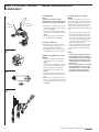
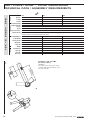
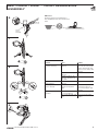
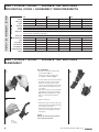
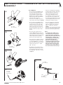
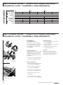
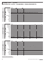
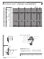
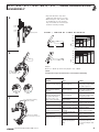
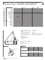
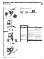
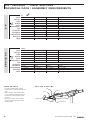
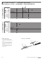
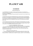
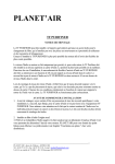
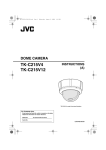
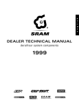
2008
NEW TECH. SPECIFICATIONS
ROAD / MTB COMPONENTS
ENGLISH
Caution:
This New Technical Specifications
are intended for bicycle factories and
wholesalers only!
© Copyright SRAM Corporation 2007
Publ. No. 95.3115.003.000 E
Information may be enhanced
without prior notice.
Released March 2007
SRAM Technical Documentation,
Schweinfurt/Germany
Teflon is a trademark of E.I. DuPont de Nemours and Co.
EXA-Drive is a trademarks of Campagnolo S.R.L., Italia.
Grilon is a trademark of EMS-Chemie AG, Switzerland.
Shimano, HG, IG, DURA-ACE are trademarks of Shimano Inc., Japan.
TABLE OF CONTENTS
ROAD / MTB COMPONENTS
ROAD COMPONENTS
Red / Force / Rival · Rear derailleurs
3
New version Red
Red / Force / Rival · Front derailleurs
6
New version Red
Red / Force / Rival · Double Tap Shifters
10
New version Red
TT
TT Shifters
12
All new
TT
TT Brake Levers
13
All new
Red / Force / Rival · Cranksets with Bottom Bracket
14
New version Red
Red / Force / Rival · Dual Pivot Road Calipers
16
New version Red
Cassettes · Road
18
New version OG 1090
Power Chains · Road
20
New versions PC 1050 / PC 1030
MTB COMPONENTS
X.0 / X-9 / X-7 / X-5 / SX 4 / 3.0 · Rear derailleurs
23
New version X-5
X-9 / X-7 / X-5 · Low Clamp Front derailleurs
27
New version X-5
X-5 / Centera · Twist shifters
30
New version X-5
X-7 / X-5 / Attack · Trigger shifters
32
New version X-5
Cassettes
34
New version PG 950
New Technical Specifications 2008 · Rev. A
1
2
New Technical Specifications 2008 · Rev. A
RED / FORCE / RIVAL · REAR DERAILLEURS
TECHNICAL DATA / ASSEMBLY REQUIREMENTS
ROAD
W
W
NNEE
Red
Speeds
Shifter Compatibility
Cogsets
Compatibility
R
E
D
F
O
R
C
E
Chains
Cranks / Chainrings
Cable & Housing
10
Force
Rival
10
10
SRAM Double Tap shifters (Red / Force / Rival)
SRAM 10 speed and other 10 speed Shimano® cogsets (largest Cog maximum 28 teeth)
SRAM 10 speed Power Chains PC 1090R / PC 1090 / PC 1070 / PC 1050 / PC 1030 and Shimano® 10 speed chains
10 speed compatible, 53-39 / 50-34 / 50-36 / 48-34 / 52-36
High quality 1.1 mm shifting cable and 4 or 5 mm compressionless housing, high quality, with non-sealed end caps of
Chain Capacity
maximum diameter 5.8 mm and maximum length 16 mm
Total
31 T
31 T
31 T
Max Sprocket
28 T
28 T
28 T
Min Sprocket
11 T
11 T
11 T
Front Difference
16 T
16 T
16 T
Titanium
Steel
Steel
Ceramic cartridge bearing
Cartridge bearing
Cartridge bearing
Yes
Yes
Yes
158 g
176 g
186 g
B-Knuckle
Forged Aluminum
Aluminum
Aluminum
Outer Link
Forged Aluminum
Aluminum
Aluminum
Inner Link
Carbon
Magnesium
Aluminum
Outer Cage
Carbon
Carbon
Aluminum
Inner Cage
Carbon
Aluminum
Aluminum
Aluminum
Aluminum
Aluminum
Parallelogram Spring
Pulleys
R
I
V
A
L
Direct Mount
Design
Weight
Hanger Bolt
DERAILLEUR ANATOMY
1
frame hanger bolt
limit screws
barrel adjuster
fin / cable guide
cable anchor bolt
12.7 mm ± 1
cable anchor washer
2
To bottom
bracket
center
R2
L
R1
90°
A
FRAME DIMENSIONS
(see figure 1 and 2)
For optimal rear derailleur performance,
the recommended rear derailleur hanger
length (L) should be 26 – 28 mm.
L
X
A
R1
R2
T
26
28
6 – 10
8 – 10
30˚ – 35˚
30˚ – 35˚
8.5 max
8.5 max
11.5 – 12.5
11.5 – 12.5
7–8
7–8
X
Chainstay length ≥ 405 mm
New Technical Specifications 2008 · Rev. A
3
RED / FORCE / RIVAL · REAR DERAILLEURS
ASSEMBLY
ASSEMBLY
1
Advice:
Check the rear derailleur hanger
alignment. A bent rear derailleur hanger
will result in inaccurate index shifting.
5 mm
8 – 10 Nm
70 – 85 in.lbs.
• Attach the rear derailleur to the frame’s
rear derailleur hanger using a 5 mm hex
head wrench (Fig. 1).
• Check that the b-adjust washer tab is
clear of the rear derailleur dropout tab
(Fig. 2).
• Tighten the 5 mm hex hanger bolt to
8 – 10 Nm (70 – 85 in.lbs.) (Fig. 1).
CHAIN LENGTH
• Bypassing the rear derailleur, run the
chain around the largest cog/large
chainring combination (Fig. 3).
• Add 2 LINKS or 1 link + connection link
to this length for proper chain length.
2
L I M I T S C R E W S A D J U S TMENT
• View the rear derailleur and pulleys
from behind the rear of the bicycle
(Fig. 4).
• Turn the limit screw marked ’H’ on the
outer link of the derailleur to align the
upper guide pulley center with the
outboard edge of the smallest cog
(Fig. 4).
• While turning the crank, push the rear
derailleur towards the larger cogs by
hand.
• Align the upper guide pulley under the
largest cog, center to center, by turning
the limit screw marked ’L’ on the outer
link (Fig. 4).
3
C H A I N G A P A D J U S TMENT
Chain gap is the distance between the
upper guide pulley and the cog the chain
is riding on. Optimal chain gap is small
enough to allow quick, efficient shifts to
and from any cog, but large enough to
allow smooth shifts to and from the largest
cog.
• Shift the chain to the small chain ring.
• Check the chain gap between the tip
of the smallest cog and the tip of the
upper guide pulley. While turning the
crank, push the rear derailleur by hand
to the largest cog and check the chain
gap in this position. (Fig. 5).
• Using a screw driver, turn the b-adjust
screw until the minimum chain gap in
either position equals approximately
6 mm.
Advice:
• Setting the chain gap at this point of
your installation may be considered a
rough estimate. Precision index shifting may require small changes of the
b-adjustment while setting the proper
cable tension.
• Do not use the b-adjust screw to adjust
the rear derailleur to act as a chaintensioning device or to prevent chain
suck. This increases the chain gap
causing poor shifting performance.
(2 Links)
4
4
New Technical Specifications 2008 · Rev. A
RED / FORCE / RIVAL · REAR DERAILLEURS
ASSEMBLY
ROAD
INDEX SHIFTING
ADJUSTMENT
5
• Check that the chain and the rear
derailleur are in the smallest cog position.
• Cut the rear piece of cable housing.
Make sure that it is not too short or long
(Fig. 6).
• Make sure the shifter cable is fully
released (hardest (highest) gear at rear
shifter).
• Turn the rear derailleur barrel adjuster
clockwise fully into the derailleur, then
back it off 1 full turn.
• Feed the rear shifter cable through the
rear derailleur cable housing, stops and
cable guides.
• Thread the cable through the rear
derailleur barrel adjuster and around
the cable guide on the fin (Fig. 6).
• Pull the cable tight and position it under
the cable anchor washer.
• Tighten the 5 mm hex cable anchor bolt
to 4 – 5 Nm (35 – 45 in.lbs.).
6 mm
(1/4" )
min.
6
• Rapidly shift the chain and derailleur up
and down the cassette several times.
If the cable slips repeat the two former
steps.
• Shift the chain to the smallest cog.
• While pedaling, move the shifter up one
detent.
– If the chain hesitates or does not shift
to the second cog, increase the cable
tension by turning the derailleur barrel
adjuster counterclockwise.
– If the chain shifts beyond the second
cog, decrease the cable tension by
turning the derailleur barrel adjuster
clockwise.
• Repeat the two former steps until shifting and cable tension is accurate.
• While turning the crank, shift the chain
up and down the cassette and chain
rings several times to ensure that your
derailleur is indexing smoothly.
5 mm
4 – 5 Nm
(35 – 45 in.lbs.)
TROUBLESHOOTING
7
Spray Lube
Spray Lube
New Technical Specifications 2008 · Rev. A
Problem
Chain jumps from smallest
sprocket to frame dropout.
Cause
High gear limit screw is not
adjusted properly.
Difficult or impossible to
shift chain onto smallest
sprocket.
High gear limit screw is not
adjusted properly.
Chain jumps over largest
sprocket and falls between
the spokes and largest
sprocket or inner cage
plate scrapes on spokes.
Delayed shifting.
Low gear limit screw is not
adjusted properly.
Rear derailleur or derailleur
hanger is bent.
Clearance between guide
pulley / sprocket is too large.
Clearance between guide
Rough shifting behavior.
pulley / sprocket is too small.
Shifts more gears onto small- Shift cable insufficiently
tensioned.
er sprockets as intended
Shift cable insufficiently
Delayed shifting onto
tensioned.
larger sprocket
Shift cable is too tight.
Delayed shifting onto
smaller sprocket
Excessive cable friction,
pinched or poorly routed
cable.
Remedy
Turn in screw H until the
guide pulley is aligned with
the smallest sprocket.
Unscrew screw H until the
guide pulley is aligned with
the smallest sprocket.
Turn in screw L until the
guide pulley is aligned with
the largest sprocket.
Straighten or replace.
Adjust b-adjust screw by
rotating counterclockwise.
Adjust b-adjust screw by
rotating clockwise.
Turn barrel adjuster on the
shifter counterclockwise.
Turn barrel adjuster on the
shifter counterclockwise.
Turn barrel adjuster on the
shifter clockwise.
Lubricate or replace cable
and housing. Check for
excessive bending of cable
housing.
5
RED / FORCE / RIVAL · FRONT DERAILLEURS
TECHNICAL DATA / ASSEMBLY REQUIREMENTS
W
W
NNEE
Red
Force
Rival
Yes
Yes
Yes
31.8 mm
with band adaptor
Yes
Yes
34.9 mm
with band adaptor
Yes
Yes
Rear Compatibility
10 speed
10 speed
10 speed
Shifter Compatible
SRAM Double Tap Shifter (Red / Force / Rival)
Clamp
Braze-on
Compatibility
R
E
D
F
O
R
C
E
Cogsets
Chains
Cranks / Chainrings
Cable & Housing
SRAM 10 speed and other 10 speed Shimano® cogsets (largest Cog maximum 28 teeth)
SRAM 10 speed Power Chains PC 1090R / PC 1090 / PC 1070 / PC 1050 / PC 1030 and Shimano® 10 speed chains
10 speed compatible, 53-39 / 50-34 / 50-36 / 48-34 / 52-36
High quality 1.1 mm shifting cable and 4 or 5 mm compressionless housing, high quality, with non-sealed end caps of
maximum diameter 5.8 mm and maximum length 16 mm
Maxim. Tooth Difference
Cable Routing
R
I
V
A
L
Chainstay Angle
Mount Type
Chain Line
16T
Bottom Pull
16T
Bottom Pull
61 – 66°
61 – 66°
61 – 66°
Down Swing
Down Swing
Down Swing
44,5 mm
44,5 mm
44,5 mm
Braze-on: 58 g / 31.8 mm: N/A / 34.9 mm: NA
Braze-on: 88 g / 31.8 mm: 102 g / 34.9 mm: 103 g Braze-on: 88 g / 31.8 mm: 102 g / 34.9 mm: 103 g
Forged Aluminum
Forged Aluminum
Forged Aluminum
Outer Link
Aluminum
Aluminum
Aluminum
Inner Link
Aluminum
Aluminum
Aluminum
Hardened Titanium
Steel Chrome Plated
Steel Chrome Plated
Weight
Band Material
Design
16T
Bottom Pull
Chain Cage
BRAZED-ON FRAME
DEFINITIONS
1
in.
mm
16 m
mm
150 ct and gs)
n
mpa inri
(Co rd Cha
da
Stan
(see Fig. 1)
The contact surface of the braze-on boss
should be aligned parallel with the centerline of the seat tube.
m
6m
R 7.
R
m
5m
m
25 m
mm
8.7
6
New Technical Specifications 2008 · Rev. A
RED / FORCE / RIVAL · FRONT DERAILLEURS
TECHNICAL DATA / ASSEMBLY REQUIREMENTS
ROAD
FRAME DIMENSIONS
2
(see Fig. 2)
The seat tube should be positioned in the
center of the bottom bracket shell.
α
Length of chainsty:
• Road L > 405 mm.
• Rear frame alignment must be
symmetrical.
Chainstay angle:
α = 61° – 66°.
15 mm max.
7 mm max.
Chainline:
44.5 mm.
(Measurement from the center of the
bracket to the center of the two chainrings.)
75 mm
110 mm
L
Hatched area can
be used by frame
design.
19.5 mm max.
34
.9
mm
15 mm max.
155 mm
105 mm
8.5 mm
Ø
15 mm max.
3
NECESSARY CLEARANCE
FOR CLAMP VERSION
C
(see Fig. 3)
Be sure to leave enough clearance
between bottle cage holes and clamp
location.
D
Necessary clearance
see Fig. 2
Large Chainring
A B
Clamp band position
48 T
50 T
52 T
53 T
A
135 mm
139 mm
143 mm
145 mm
B
152 mm
156 mm
160 mm
162 mm
Clamp version
Necessary clearance
New Technical Specifications 2008 · Rev. A
Red
Force / Rival
C
9 mm
4 mm
D
1 mm
4 mm
7
RED / FORCE / RIVAL · FRONT DERAILLEURS
ASSEMBLY
ASSEMBLY
• Tighten the 5 mm hex cable anchor bolt
to 5 Nm (44 in.lbs.).
• Only version Red: Mount the front derailleur to the clamp adaptor. Tighten the
• Shift the chain up and down the chain5 mm hex clamp bolt to 4 – 5 Nm (35 – 44
rings several times to take out initial
in.lbs.) (Fig. 1).
slack in the cable.
• Attach the front derailleur to the seat
• If necessary re-tension the cable and
tube.
tighten cable anchor bolt.
Direct mount version (see Figure 2): use
upper thread for compact chainrings
(50-36 / 50-34 / 48-34) or lower thread for H I G H L I M I T A D J U S T M E N T
standard chainrings (53-39 / 52-36).
(see Fig. 7)
1
1.
2.
5 mm
4 – 5 Nm
35 – 44 in.lbs.
compact
50-36 / 50-34 / 48-34
2
• Adjust the position along the seat tube
so that clearance between the front
derailleur cage and the large chainring
is 1 – 3 mm (Fig. 3).
At the same time, align the front derailleur cage outerplate to be parallel with
the chainrings (Fig. 4).
standard
53-39 / 52-36
• Tighten the 5 mm hex clamp bolt to
4 – 5 Nm (35 – 44 in.lbs.) for direct mount
version or 3 – 4 Nm (27 – 35 in.lbs.) for
version with band adatpor or 5 – 7 Nm
(44 – 62 in.lbs.) for clamp version.
5 mm
4 – 5 Nm
35 – 44 in.lbs.
LOW LIMIT ADJUSTMENT
(see Fig. 5)
• Place the chain on the largest rear cog
and the small front chainring.
• Adjust the low limit screw (Fig. 5) so
that the chain is positioned close to
the inner cage plate without actually
touching it (clearance between the
front derailleur cage inner plate and the
chain is 0.5 – 1 mm).
3
1 – 3 mm
• Set the chain to the smallest rear cog
and the large front chainring.
• Adjust the high limit screw so that
clearance between the front derailleur
cage outer plate and the chain is
0.5 – 1 mm.
INDEX SHIFTING
ADJUSTMENT
(see Fig. 8)
Version Red:
Shift the chain onto the biggest rear
sprocket and big chainring. Make sure the
left shifter is set in the middle position – if
the chain scrapes against the inner cage
plate, turn the adjusting barrel on the
frame until the chain shifts smoothly and
free of obstruction.
Versions Force / Rival:
Shift the chain onto the smallest rear
sprocket and small chainring. Make sure
the left shifter is set in the middle position
– if the chain scrapes against the inner
cage plate, turn the adjusting barrel on
the frame until the chain shifts smoothly
and free of obstruction.
CONNECTING CABLE
• Check that the chain and the front
derailleur are in the small chainring
position.
4
Clamp version
5 mm
5 – 7 Nm
44 – 62 in.lbs.
• Make sure the shifter cable is fully
released (easiest (lowest) gear for front
shifter).
• Turn the barrel adjuster on the frame
fully into the housing, then turn 1 full
turn back.
5
Version with clamp
adaptor
5 mm
3 – 4 Nm
27 – 35 in.lbs.
• Feed the front shifter cable through the
cable housing and stops. Route cable
through a cable guide beneath the bottom bracket.
• Run the cable under the cable anchor
washer and hold taut (Fig. 6).
8
New Technical Specifications 2008 · Rev. A
RED / FORCE / RIVAL · FRONT DERAILLEURS
ASSEMBLY
ROAD
ADVICE
6
Avoid using extreme gear combinations as
these combinations cause noise and excessive
wear!
5 mm
5 Nm
44 in.lbs.
7
TROUBLESHOOTING
Cause
Problem
Shifter actuated, chain fails Shift cable incorrectly
clamped.
to change chainring.
8
Chain falls over large /
small chainring.
Force required to actuate
gears is too high.
Crank collides with front
derailleur.
Remedy
Check shift cable and
correct as necessary (cable
clamp; cable housing stops;
cable recess in shifter; cable
tension).
High / low limit screw poorly Correct limit screws.
adjusted.
Clearance between cage
Correct position (1 – 3 mm).
and large chainring is too
big / small.
High / low limit screw poorly Correct limit screws.
adjusted.
Excessive cable friction,
Lubricate or replace cable
pinched or poorly routed
and housing. Check for
cable.
excessive bending of cable
housing.
High gear limit screw
Correct high limit screw.
incorrectly adjusted.
Cage not parallel with chain- Correct the front derailleur
ring.
position.
9
New Technical Specifications 2008 · Rev. A
9
RED / FORCE / RIVAL · DOUBLE TAP SHIFTERS
TECHNICAL DATA / ASSEMBLY REQUIREMENTS
R
E
D
Shifter Type
Speeds
Compatibility
F
O
R
C
E
Red
Version
Double Tap Shifter
Double Tap Shifter
Double Tap Shifter
Double Tap Shifter
Front
Rear
Front
Rear
Front
Rear
2
10
2
10
2
10
SRAM Red / Force / Rival
Crankset
SRAM Red / Force / Rival
Brakes
Rival
Double Tap Shifter
Derailleur
SRAM Red / Force / Rival Dual Pivot Road calipers, Avid Shorty 4/6 cantilevers, Avid BB7 Road and most common Road caliper brakes
Shifter Cable
high quality 1.1 m m shifting cable and 4 or 5 mm compressionless housing, high quality, with non-sealed end caps of maximum
Brake Cable
1.6 mm high quality brake cable with road-style cable end and brake cable housing with end caps
diameter 5.8 mm and maximum length 16 mm
Cable Pull Release
R
I
V
A
L
Force
Double Tap Shifter
Double Tap
Double Tap
Double Tap
Double Tap
Double Tap
Double Tap
Teflon Coat. Stainl. Steel Teflon Coat. Stainl. Steel Teflon Coat. Stainl. Steel Teflon Coat. Stainl. Steel Stainless Steel
Stainless Steel
Brake and shift lever Brake and shift lever None
None
None
None
Gear Indication
None
None
None
None
None
None
Barrel Adjuster
None
None
None
None
None
None
22.1 – 22.3 mm
22.1 – 22.3 mm
22.1 – 22.3 mm
22.1 – 22.3 mm
22.1 – 22.3 mm
22.1 – 22.3 mm
280 g
280 g
303 g
303 g
340 g
340 g
Cable
Reach Adjust
Clamping Diameter
Weight
RED / FORCE / RIVAL · DOUBLE TAP SHIFTERS
ASSEMBLY
ASSEMBLY
1
3
• Flip hood cover by hand. Slide shifter
onto handlebar (Fig. 1).
Tighten the 5 mm hex clamp bolt to
6 – 8 Nm (53 – 70 in.lbs.) (Fig. 2).
• Feed the shifter cables and brake cables
through the cable housings and stops.
Make sure the shifter cable is fully
released (easiest (lowest) gear for front
shifter or the hardest (highest) gear for
rear shifter).
Red shifters: Choose the one shift cable
exit which fits best for your handlebar
(Fig. 3). It may be helpfull to use a pick.
There is no need to disassemle the
shifter.
2
• Replace hood cover.
• Attach the front/rear shifter cable to the
front/rear derailleur and adjust indexing
per derailleur instructions.
Attach the front/rear brake cable to the
front/rear brake and adjust per brake
instructions.
Caution:
Always check the front and rear brake
levers for proper operation.
5 mm
6 – 8 Nm
53 – 70 in.lbs.
10
New Technical Specifications 2008 · Rev. A
RED / FORCE / RIVAL · DOUBLE TAP SHIFTERS
USE
1
0°
X°
CLICK
XX°
CLI
CL CLICK CK
ICK
0
ROAD
USE
BRAKE LEVER
SHIFTER
Caution:
Always check the front and rear brake
levers for proper operation!
• Move the small shift lever inward
slightly and an upshift to a harder
(higher) gear is initiated (Fig. 1).
Push the same lever farther inward
and you’re shifting up to three shifts to
easier (lower) gears (Fig. 1).
The shifters also offer specific operations:
• Upshifting while sprinting:
2
• Shifting from the hoods:
REACH ADJUST
Brake lever (Fig. 3):
• Flip hood cover by hand.
• Use the small hex clamp bolt (2 mm) to set
the reach adjust of the brake lever.
Caution:
After any change on the reach adjust
of the brake lever allways re-adjust
the shift lever to avoid interference
between the two levers.
Shift lever (Fig. 4):
Pull the shift lever toward the handlebar
While pushing turn the cam plate to set the
reach adust. It may be helpfull to use a pick.
Caution:
Always check the front and rear brake
levers for proper operation!
• Shifting from the drops:
3
• The left hand shifter offers a trim
function for the front derailleur to allow
the chain running smoothly in extreme
positions.
Force and Rival shifters: Shift position
1 and 2 is for the small chainring. Shift
position 3 is for the large chainring.
Red shifter: Shift position 1 is for the
small chainring. Shift position 2 and 3 is
for the large chainring.
4
New Technical Specifications 2008 · Rev. A
11
TT SHIFTERS
TECHNICAL DATA / ASSEMBLY REQUIREMENTS
TT Shifter
Version
T
T
Speeds
Derailleur
Compatibility
S
H
I
F
T
E
R
Shifter Type
Crankset
Time Trial Shifter
Time Trial Shifter
Front (Friction)
Rear (Index)
2
10
SRAM Red / Force / Rival SRAM Red / Force / Rival
SRAM Red / Force / Rival SRAM Red / Force / Rival
Shifter Cable
high quality 1.1 m m shifting cable and 4 or 5 mm compressionless housing, high quality, with non-sealed end caps of maximum
Brake Cable
1.6 mm high quality brake cable with road-style cable end and brake cable housing with end caps
diameter 5.8 mm and maximum length 16 mm
Bar Inner Diameter
Cable
19.2 – 22.5 mm / Minimum depth 35 mm
Teflon Coat. Stainl. Steel Teflon Coat. Stainl. Steel
Gear Indication
None
None
Barrel Adjuster
None
None
Weight
138 g
138 g
TT SHIFTERS
ASSEMBLY
ASSEMBLY
1
• Remove screw to allow shift assembly to
be removed from housing and to access
the mounting screw (Fig. 1).
Advice:
The shift assembly comes off as one
piece and there is no opportunity to
loose any parts unless the other screw
is removed.
• Push the shifter housing onto the
handlebar (Fig. 2).
2
4
5 Nm
44 in.lbs.
5
• Tighten the the clamp screw using a
5 mm Allen wrench, torque 8 Nm (70
in.lbs.) (Fig. 3).
• Re-assemble the shift assembly and reinstall the screw, tightening torque 5 Nm
(44 in.lbs.) (Fig. 4).
• Torque the friction adjust screw (center
of red washer) to 2 Nm (18 in.lbs.) minimum. Higher torque can be applied to
increase torque to shift for rider preference (Fig. 5).
3
min. 2 Nm
min. 18 in.lbs.
6
• Feed the new cable through the cable
entry (1) and out the shifter (Fig. 6).
• Feed the new cable through the cable
housing and cable stops.
5 mm
8 Nm
70 in.lbs.
12
• Pull the cable snug. Make sure that the
cable nipple is firmly seated in the cable
holder.
1
• Attach the cable to the derailleur and
adjust indexing per derailleur instructions.
New Technical Specifications 2008 · Rev. A
TT BRAKE LEVERS
TECHNICAL DATA / ASSEMBLY REQUIREMENTS
ROAD
TT Brake Lever
Version
Brake Lever
Compatibil.
Lever Size
Time Trial Brake Lever
Time Trial Brake Lever
Left
Right
5-finger
5-finger
Brake compatibilty
SRAM Red / Force / Rival Dual Pivot Road calipers, Avid Shorty 4/6 cantilevers, Avid BB7 Road
Bar Inner Diameter
19.2 – 22.5 mm / Minimum depth 39 mm
and most common Road caliper brakes
Reach Adjust
No
No
Pivot Bushing
POM
POM
99 g
99 g
Grilon Composite
Grilon Composite
Carbon Comp.
Carbon Comp.
Weight
Design
T
T
B
R
A
K
E
L
E
V
E
R
TT
Housing
Lever
TT BRAKE LEVERS
ASSEMBLY
ASSEMBLY
1
• Push the cable housing end cap
onto the brake cable housing (Fig. 1).
1
• Insert the end of the brake cable housing into the brake lever bottom side (Fig.
2).
5 mm
8 Nm
70 in.lbs.
• Push the brake lever onto the handlebar
(Fig. 3).
• Tighten the brake lever. 5 mm Allen
wrench, torque 8 Nm (70 in.lbs.) (Fig. 4).
2
• Pull the brake handle toward the handlebar
and make sure the countersunk side of
the hole is visible (1). Feed the new cable
through the cable holder (2), cable housing
and cable stops (Fig. 5).
• Pull the cable snug. Make sure that the
cable nipple is firmly seated in the cable
holder.
2
1
• Follow the brake manufacturer's
instructions when mounting the brake
cable and adjusting the brakes.
2
Caution:
• Before riding, always check that all
brake system components are functioning properly.
• Check and correct the brake cable tension after each handle change to ensure
good brake performance.
New Technical Specifications 2008 · Rev. A
2
13
RED / FORCE / RIVAL · CRANKSETS W. GXP BOTTOM BRACKET
TECHNICAL DATA / ASSEMBLY REQUIREMENTS
R
E
D
R
I
V
A
L
Compatibility
BB Thread
Red Compact
Force
Force Compact
GXP External Bearing
GXP External Bearing
BSA or Italian
Rival
Rival Compact
GXP External Bearing
BSA or Italian
BSA or Italian
Bolt Circle Diam.
130 mm
110 mm
130 mm
110 mm
130 mm
110 mm
Chainring Ratio
53 / 39 T
50 / 34 – 50 /36 T
53 / 39 T
50 / 34 – 50 /36 T
53 / 39 T
50 / 34 – 50 /36 T
Only compat. with SRAM 10 speed chains
SRAM 10 speed chains PC1090R/PC1090/PC1070/PC1050/PC1030 and Shimano® 10 speed chains
Chainline
44.5 mm
44.5 mm
44.5 mm
Minimum Chainstay
405 mm
405 mm
405 mm
165 / 170 / 172.5 / 175 / 177.5 / 180 mm
165 / 170 / 172.5 / 175 / 177.5 / 180 mm
165 / 170 / 172.5 / 175 / 177.5 / 180 mm
Ceramic Sealed Cartridge Bearing
Sealed Cartridge Bearing
Sealed Cartridge Bearing
Weight
765 g
790 g
BB Cup
Forged Alloy
Chains
Crank Lengths
Bearing
Finish
F
O
R
C
E
Red
BB Type
765 g
Crank Arm Carbon Fibre
Chainring
780 g
Forged Alloy
AL 7075-T6 Aluminum with TNT Finish
Chainring Bolts AL 7075-T6 Aluminum
850 g
840 g
Forged Alloy
Carbon Fibre
AL 6066 Aluminum
AL 7075-T6 Aluminum with TNT Finish
AL 7075-T6 Aluminum with Hard Anodizing
AL 7075-T6 Aluminum
AL 7075-T6 Aluminum
Cranks are only compatible with GXP bottom brackets and Powerglide Chainrings by Truvativ.
RED / FORCE / RIVAL · CRANKSETS W. GXP BOTTOM BRACKET
ASSEMBLY
NECESSARY TOOLS
1
ASE
Bearing face
Drive side (Right)
Non-drive side (Left)
GRE
Threads
O-Rings
Bearing seal surface
Note:
Note:
Drive side bearing seal has
Non-drive side bearing seal
larger inner diameter than
has smaller inner diameter
non-drive side seal
than drive-side seal
2
• Torque wrench
• 8 mm hex, 16 mm (5/8”) hex
• Bottom Bracket installation tool (Truvativ
GXP tool, Park™ BBT9 or equivalent)
Supplies:
• Grease
PARTS PREPARATION
• Assure the frame’s bottom bracket shell
threads are clean and undamaged, there
should be no paint or dirt present. Have
your bottom bracket shell chased and
faced by your bike shop for best results.
Check to make sure the threads of your
GXP bottom bracket match the threads in
the bottom bracket shell of your frame.
• Prepare the bottom bracket as shown in
Figure 1.
It may be necessary to remove the drive
side seal from the spindle.
Both seals should be pressed into place
so that the outer lip seats firmly in the
bottom bracket cup groove. Apply grease
to the surfaces shown in Figure 1.
• Prepare the crank spindle:
– Apply grease to splines (1, Figure 2)
– Apply grease to crankbolt threads (2)
– Apply grease to spindle bearing race
surfaces (3)
• Prepare the self extracting crank bolt:
Apply grease to the surfaces shown in
Figure 3.
3
GREA
SE
1
2
3
GREAS
14
E
New Technical Specifications 2008 · Rev. A
RED / FORCE / RIVAL · CRANKSETS W. GXP BOTTOM BRACKET
ASSEMBLY
ROAD
ASSEMBLY
4
English
(BSA)
GRE
ASE
34 – 41 Nm
(301 – 363 in.lbs.)
Italian
(IT)
5
GREA
SE
34 – 41 Nm
(301 – 363 in.lbs.)
6
• Grease frame threads (Fig. 4). Thread
the prepared bottom bracket into the
drive side (right side) of the frame
(counterclockwise to tighten English
(BSA) thread or clockwise to tighten
Italian thread) until the flange bottoms
against the frame shell face.
Torque to 34 – 41 Nm (301 – 363 in.lbs.)
using a torque wrench. Refer to Figure 4.
• Check the assembly for play by pulling
crankarm away from frame, alternating
back and forth. If the crank moves,
tighten crankarm bolt until no play
is detected. If maximum torque of
48 – 54 Nm (425 – 478 in.lbs.) has been
achieved, remove the crankarm from
the spindle, apply additional grease, and
repeat installation. It may take several
installations to eliminate all play.
• Grease frame threads (Fig. 5). Thread
the prepared left adapter cup into the
non-driveside (left side) of the frame
(Clockwise to tighten) until the flange
bottoms against the frame shell face.
Torque the left adapter cup to 34 – 41
Nm (301 – 363 in.lbs.) using a torque
wrench.
• Grease the pedal threads, add pedal
washers (1, Figure 8), assemble and
tighten the pedals to the crankarms
with 31 – 34 Nm (274 – 301 in.lbs.).
Caution:
Drivetrain side right hand pedal-thread.
Non drive side left hand pedal-thread.
• Grease the inner bearing races as
shown in Figure 6. Slide the right crankarm and spindle assembly through the
bottom bracket until the left side splines
come through the left side bottom
bracket cup, and the spindle stops.
Advice:
• If creaking of the assembly occurs,
check that all parts were torqued to
specification, grease is liberally applied on all surfaces noted. Also check
chainring bolts (8 – 9 Nm / 80 – 90
in.lbs.) and pedals are installed with
proper lubrication and torque.
• GXP seals are designed to prevent
contamination and therefore must rub
against their sealing surfaces. New
GXP seals will feel stiff upon initial
installation. This is normal. With use
the seals will wear-in and loosen up.
• If the crank bolt assembly has not been
assembled yet, assemble it and torque
as shown in Figure 7. Use a 16 mm hex
(5/8”) and torque wrench to install self
extractor and torque to 12 – 15 Nm
(106 – 133 in.lbs.).
• Assemble the left crankarm onto the
bottom bracket spindle using an 8 mm
hex and torque wrench and torque to
48 – 54 Nm (425 – 478 in.lbs.) as shown
in Figure 8.
8
31 – 34 Nm
274 – 301 in.lbs.
GREAS
E
1
7
16 mm (5/8“)
12 – 15 Nm
106 – 133 in.lbs.
1
8 mm
48 – 54 Nm
425 – 478 in.lbs.
31 – 34 Nm
274 – 301 in.lbs.
New Technical Specifications 2008 · Rev. A
15
RED / FORCE / RIVAL · DUAL PIVOT ROAD CALIPERS
TECHNICAL DATA / ASSEMBLY REQUIREMENTS
Red
Compat.
Version
Brake Levers
Brake Cable
Pad
Design
B
R
A
K
E
C
A
L
I
P.
Front
Force
Rear
Front
Rival
Rear
Front
Rear
SRAM Red / Force / Rival Double Tap shifters
1.6 mm high quality brake cable with road-style cable end and brake cable housing with end caps
Exchangeable
Exchangeable
Exchangeable
Quick Release
Yes
Yes
Yes
Barrel Adjuster
Yes
Yes
Yes
Weight per Set
265 g (front and rear) 265 g (front and rear) 279 g (front and rear) 279 g (front and rear) 289 g (front and rear) 287 g (front and rear)
Pivot Bolt
Arms
Titanium
Titanium
Stainless Steel
Cold Forged Aluminum
Cold Forged Aluminum
Cold Forged Aluminum
RED / FORCE / RIVAL · DUAL PIVOT ROAD CALIPERS
TECHNICAL DATA / ASSEMBLY REQUIREMENTS
ASSEMBLY
1
Install the brake caliper:
Hold the brake so it is approximately
centered on the wheel, then tighten the
brake mounting nut with a 5 mm Allen
wrench, tighten to 8 – 10 Nm (70 – 90
in.lbs.) (Figure 1).
Position the brake pads:
Adjusting the brake pad position as shown
in figure 2. Toe-in, the angle of contact
between the pad and the rim, can also
be adjusted to optimize braking feel and
performance.
5 mm
8 – 10 Nm
70 – 90 in.lbs.
2
Center the brake pads:
• Loosen the m ounting nut of the caliper
brake a bit (Figure 6).
• Use a 12 mm wrench to precisely center
the brake to the rim.
• Re-tighten the brake mounting nut to
8 – 10 Nm (70 – 90 in.lbs.).
Inspection:
Squeeze brake lever hard 10 times
to check that everything is operating
correctly, then re-check the brake pad
position and clearance to the rim.
• Tighten the brake pad bolt with a 4 mm
allen key to 5 – 7 Nm (44 – 62 in.lbs.).
Connect the brake cable:
• Make certain the quick release lever is
in the closed position (Figure 3).
• Place the cable in the groove in the
cable clamp washer (Figure 4).
• Squeeze the brake caliper until each
brake pad is 1 – 1.5 mm from the rim.
• Tighten the cable bolt to 6 – 8 Nm
(53 – 70 in.lbs.).
4 mm
5 – 7 Nm
44 – 62 in.lbs.
16
• Turn the barrel adjuster to reset the
shoe clearance (1 – 1.5 mm) (Figure 5).
New Technical Specifications 2008 · Rev. A
RED / FORCE / RIVAL · DUAL PIVOT ROAD CALIPERS
ASSEMBLY
For Brake Lever information please read
the integrated brake shifter User Manual.
3
Caution:
• Brakes are a safety-critical item on
a bicycle. Improper set-up or use of
brakes can result in loss of control
or an accident, which could lead to a
severe injury. It is your responsibility
to learn proper braking techniques.
Consult the user manual for your
bicycle and a professional bike
dealer. Practice your riding and braking
techniques on a flat and level surface
prior to aggressive riding.
• The effectiveness of braking is
dependent on many conditions over
which SRAM has no control including
the speed of the bicycle, type and
condition of the riding surface, braking
lever force, proper installation and
maintenance of brakes, cables, levers,
brake pads, the condition of the bike,
weight of the rider, braking technique,
weather, and a variety of other factors.
Remember, it takes longer to stop in
wet conditions.
• SRAM brakes and levers are not
intended for use on any motorized
bicycle or vehicle. Any such use could
result in a serious personal injury.
• Inspect your brakes regularly for
damage, and always inspect them
thoroughly after any crash or severe
impact. If you detect damage, please
have your brakes inspected by a
professional bike dealer.
• Follow these instructions carefully. If
you do not understand the instructions,
have the installation done by a professional bike mechanic.
4
6 – 8 Nm
53 – 70 in.lbs.
5
ROAD
Advice;
• SRAM’s road brake pads are optimized
for aluminum rims. If used with ceramiccoated or carbon rims, the brake pads
will wear more rapidly. Be certain to
inspect them often.
• If the brake pads are worn until the
grooves disappear, replace them with
new pads.
6
5 mm
8 – 10 Nm
70 – 90 in.lbs.
New Technical Specifications 2008 · Rev. A
17
CASSETTES · ROAD
TECHNICAL DATA / ASSEMBLY REQUIREMENTS
W
W
NNEE Road
W
W
NNEE
Application
Road
Technology
Open Glide
Open Glide
Largest Cog
26 T
23 T
Speeds
10
10
Chains
SRAM 10 speed Power Chains PC 1090R, PC 1090, PC 1070, PC 1050, PC 1030 and Shimano® 10 speed chains
Hubs
Any hub with Shimano® compatible driver body (not compatible with Shimano® DURA-ACE 10 speed cassettes bodies)
Cogs
11/12/13/14/15/17/19/21/23/26 11/12/13/14/15/16/17/19/21/23
Lockring torque
Weight
Cogs
Design
O
G
1
0
9
0
Compatibility
OG 1090
Spider
40 Nm
40 Nm
N/A
N/A
Heat treated steel / Titan Heat treated steel / Titan
Carbon
Carbon
Aluminum, anodized
Aluminum, anodized
Rivets
N/A
N/A
Finish
N/A
N/A
Lockring
Road
Road
Technology
Open Glide
Open Glide
Open Glide
Open Glide
Open Glide
Largest Cog
26 T
26 T
23 T
25 T
25 T
Speeds
10
10
10
10
10
Chains
SRAM 10 speed Power Chains PC 1090R, PC 1090, PC 1070, PC 1050, PC 1030 and Shimano® 10 speed chains
Cogs
12/13/14/15/16/17/19/21/23/26 11/12/13/14/15/17/19/21/23/26 11/12/13/14/15/16/17/19/21/23 12/13/14/15/16/17/19/21/23/25 11/12/13/14/15/17/19/21/23/25
Cogs
Spider
Lockring
40 Nm
40 Nm
40 Nm
40 Nm
40 Nm
243 g
232 g
210 g
238 g
223 g
Heat treated steel
Heat treated steel
Heat treated steel
Heat treated steel
Heat treated steel
Aluminum 6061
Aluminum 6061
Aluminum 6061
Aluminum 6061
Aluminum 6061
Aluminum, anodized
Aluminum, anodized
Aluminum, anodized
Aluminum, anodized
Aluminum, anodized
Rivets
Stainless Steel
Stainless Steel
Stainless Steel
Stainless Steel
Stainless Steel
Finish
Pearl Ni-Chrome Plated Pearl Ni-Chrome Plated Pearl Ni-Chrome Plated Pearl Ni-Chrome Plated Pearl Ni-Chrome Plated
Compatibility
W
W Road
NNEE
W
W
NNEE
Application
Road
Technology
Open Glide
Open Glide
Largest Cog
27 T
28 T
Speeds
10
10
Chains
SRAM 10 speed Power Chains PC 1090R, PC 1090, PC 1070, PC 1050, PC 1030 and Shimano® 10 speed chains
Hubs
Any hub with Shimano® compatible driver body (not compatible with Shimano® DURA-ACE 10 speed cassettes bodies)
Cogs
12/13/14/15/16/17/19/21/24/27 11/12/13/14/15/17/19/22/25/28
Lockring torque
Weight
Cogs
Spider
40 Nm
40 Nm
243 g
242 g
Heat treated steel
Heat treated steel
Aluminum 6061
Aluminum 6061
Aluminum, anodized
Aluminum, anodized
Rivets
Stainless Steel
Stainless Steel
Finish
Pearl Ni-Chrome Plated Pearl Ni-Chrome Plated
Lockring
9 / 8 speed cassettes see page 58 and 59.
18
W
W
NNEE
Any hub with Shimano® compatible driver body (not compatible with Shimano® DURA-ACE 10 speed cassettes bodies)
Weight
Design
Road
Hubs
OG 1070
O
G
1
0
7
0
Road
W
W
NNEE Road
Application
Lockring torque
Design
O
G
1
0
7
0
Compatibility
OG 1070
New Technical Specifications 2008 · Rev. A
CASSETTES · ROAD
ASSEMBLY
ROAD
ASSEMBLY
1
The sprockets are arranged on a plastic
support (Speedloader).
• Remove the transportation lock.
• Versions with sprockets with 11 teeth:
Remove the lockring from the front and
the sprocket with 11 teeth from the back
of the Speedloader.
• Versions with sprockets with 12 teeth:
Remove the lockring from the Speedloader.
• Align the spline patterns of the Speedloader with the driver of the hub and
press the Speedloader against the
driver (Figure 1).
2
• Push the cassette from the Speedloader
onto the driver of the hub.
Advice:
Cassettes with carbon spiders: Make
sure to mount the steel washer (thickness 1 mm) between the driver and the
cassette.
• Only versions with sprockets with 11
teeth:
Position the sprocket with 11 teeth on
the driver (Figure 2).
3
• Screw the lockring into the driver. Use
a mounting tool (1, Fig. 3) (Park Tool®
FR-5 or Shimano®) and a chain wrench
(2, Fig. 3). Tightening torque 40 Nm (350
in.lbs.) (Figure 3).
1
Advice:
Be careful not to damage the thread of the
lockring by tilting.
• After installing the rear wheel adjust the
rear derailleur per derailleur instructions.
2
New Technical Specifications 2008 · Rev. A
19
POWER CHAINS · ROAD
TECHNICAL DATA / ASSEMBLY REQUIREMENTS
P
O
W
E
R
Application
Max. No. of sprockets
Pin
PC 1050
Road
Road
PC 1030
Road
10 only
10 only
10 only
10 only
10 only
SRAM OG / HG / EXA-Drive SRAM OG / HG / EXA-Drive SRAM OG / HG / EXA-Drive SRAM OG / HG / EXA-Drive SRAM OG / HG / EXA-Drive
Riveting
Chrome Hardened
1
/2" x 11/128"
1
/2" x 11/128"
1
/2" x 11/128"
1
/2" x 11/128"
1
/2" x 11/128"
5.87 mm
5.87 mm
5.87 mm
5.95 mm
5.95 mm
Cylindrical
Cylindrical
Cylindrical
Flat Cylindrical
Flat Cylindrical
Yes
Yes
Yes
Yes
Yes
2000 N / 450 lbs.
2000 N / 450 lbs.
2000 N / 450 lbs.
2000 N / 450 lbs.
2000 N / 450 lbs.
9000 N / 2023 lbs.
9000 N / 2023 lbs.
9000 N / 2023 lbs.
9000 N / 2023 lbs.
9000 N / 2023 lbs.
Weight (114 links)
257 g
265 g
265 g
277 g
277 g
External Pin Plate
Silver / Nickel Plated
Silver / Nickel Plated
Silver / Nickel Plated
Silver / Nickel Plated
Silver / Nickel Plated
Silver / Nickel Plated
Silver / Nickel Plated
Grey
Silver / Nickel Plated
Grey
Power Lock 10 Speeds
Power Lock 10 Speeds
Power Lock 10 Speeds
Power Lock 10 Speeds
Power Lock 10 Speeds
Min. Tensile Strength
Internal Pin Plate
Connecting Method 1
Caution: Connecting method: with Power Lock only (no pin)!
9 / 8 speed chains see page 62.
20
NEW
NEW
Compatibility Rear
Push Power
Design
PC 1070
Road
Truvativ / HG / EXA-Drive Truvativ / HG / EXA-Drive Truvativ / HG / EXA-Drive Truvativ / HG / EXA-Drive Truvativ / HG / EXA-Drive
Length
1
PC 1090
Road
Compatibility Front
Dimension
C
H
A
I
N
S
NEW
NEW
PC 1090R
New Technical Specifications 2008 · Rev. A
POWER CHAINS · ROAD
ASSEMBLY
1
(1 Link + Power Lock)
2
ROAD
PC 1090R / PC 1090 /
PC 1070 / PC 1050 / PC 1030
( 1 / 2 " x 11 / 128 " )
Opening:
Once the Power Lock is installed it can
only be removed by means of a Chain tool.
Chain length:
(A chain tool will be required to shorten
the chain.)
• Replacing a worn chain:
Measure the worn chain and shorten the
new to the same length.
• Initial assembly:
Shorten the chain to the length specified by the derailleur manufacturer.
SRAM derailleurs:
place the chain over largest front chainwheel and largest rear sprocket and add
1 link + Power Lock (Fig.1).
Caution:
• Power Lock is for one-time use only!
• Always use a new Power Lock when
fitting a new chain.
• Failure to shorten the chain properly or
to lock it exactly into place may cause
damage to the chain and eventually
total chain failure, material damage or
the rider to fall off his bicycle resulting
in injury.
• Worn sprockets should also be replaced when a new chain is fitted.
Closing chain with Power Lock:
Caution:
• Use Power Lock only with SRAM
chains!
• Use only Power Lock to close 10 speed
chains (no Pin)!
• Use only Power Lock (black coloured)
for PC 1090R, PC 1090, PC 1070, PC 1050,
PC 1030 to avoid material damage or the
rider to fall off his bicycle resulting in
injury.
3
• Fit chain, insert both halves of the
Power Lock into the chain ends (Fig. 2)
and bring the ends together (Fig. 3) on
the bottom side of the drivetrain (no tension side).
• Pull chain apart until you feel some
resistance (Fig. 4).
• Rotate the chain so the Power Lock is
positioned on the top side of the drivetrain (Fig. 5).
• Pedal forward while holding bike firmly
in place (Fig. 5) until you hear click
sound. The Power Lock is now on its
place and safely closed.
4
5
New Technical Specifications 2008 · Rev. A
21
22
New Technical Specifications 2008 · Rev. A
X.0 / X-9 / X-7 / X-5 / SX 4 / 3.0 · REAR DERAILLEURS
TECHNICAL DATA / ASSEMBLY REQUIREMENTS
MTB
X
.
0
Compatib.
Speeds
Cogsets & Chains
Chainrings
Total
Chain Capacity
X
9
Shifter Compatibility
X
7
Cage Length
9/8
9/8
9/8
9/8
W
W
NNEE
SRAM 1:1 Actuation Ratio 9 / 8 speed shifters
SRAM / IG & HG 9/8spd
SX 4
3.0
8/7
8/7
SRAM 1:1 8 / 7spd shifters
SRAM / IG & HG 9/8spd
SRAM / IG & HG 9/8spd
SRAM / IG & HG 9/8spd
SRAM / IG & HG 8/7spd
22-32-42/44, 24-34-46, 26-36-46/48
45 T
37 T
Long
Medium Short
30 T
45 T
37 T
45 T
37 T
45 T
37 T
45 T
Long
Medium
Long
Medium
Long
Medium
Long Med. Long
37 T 45 T
34 T
34 T
34 T
34 T
34 T
11 T
11 T
11 T
11 T
11 T
11 T
Front Difference
22 T
22 T
22 T
22 T
22 T
22 T
Titanium
Steel
Steel
Steel
Steel
Steel
Cartr. bearing, stainless Cartr.bear./Bush., hard.
Bushing, hardened
Bushing
Bushing
Bushing
Yes
Yes
Yes
Yes
Yes
Cable & Housing
Weight
Design
X5
34 T
Pulleys
3
.
0
X-7
Min Sprocket
Direct Mount
S
X
4
X-9
Max Sprocket
Parallelogram Spring
X
5
X.0
Yes
1.1 or 1.2 mm high quality cables, 4 or 5 mm compressionless cable housing with end cap / maximum diameter of 5.8 mm
210 g
197 g
192 g
230 g
225 g
275 g
N/A
309 g
N/A
309 g N/A 275 g
B-Knuckle
Forged Aluminum / Anod. Aluminum
Aluminum
Aluminum
Aluminum
Compos.
Outer Link
Forged Aluminum
Alu die-cast / Painted
Alu die-cast / Painted
Aluminum
Zinc Alloy
Compos.
Inner Link
Forged Aluminum
Aluminum / Anodized
Steel / E-coat
Steel / E-coat
Composite Steel
Outer Cage
Alumin. Carbon Composite Stamped AL / Anodized
Stamped AL / Anodized
Steel / E-coat
Steel / E-coat
Inner Cage
Alumin. Carbon Composite Stamped AL / Anodized
Steel
Steel
Steel
Aluminum / Anodized
Aluminum / Anodized
Steel
Steel
Hanger Bolt
Aluminum / Anodized
Compos.
DERAILLEUR ANATOMY
1
cable stop
frame hanger bolt
b-adjust screw
limit screws
fin / cable guide
cable anchor bolt
cable anchor washer
12.7 mm ± 1
2
FRAME DIMENSIONS
To bottom
bracket
center
R2
L
R1
90°
A
X
New Technical Specifications 2008 · Rev. A
(see figure 1 and 2)
• For optimal 1:1 Actuation Ratio rear derailleur performance, the recommended
rear derailleur hanger length (L) should
be 28 – 30 mm.
• For a given L, use the chart below to
determine other 1:1 Actuation Ratio
rear derailleur hanger specifications.
L
X
A
R1
R2
T
28
30
6 – 10
7.5 – 10
25˚ – 30˚
25˚ – 30˚
8.5 max
8.5 max
11.5 – 13.5
11.5 – 13.5
7–8
7–8
23
X.0 / X-9 / X-7 / X-5 / SX 4 / 3.0 · REAR DERAILLEURS
ASSEMBLY
ASSEMBLY
1
Advice:
Check the rear derailleur hanger
alignment. A bent rear derailleur hanger
will result in inaccurate index shifting. Outboard side impacts are the most
common causes of this type of damage.
5 mm
8 – 10 Nm
70 – 85 in.lbs.
• Attach the rear derailleur to the frame’s
rear derailleur hanger using a 5 mm hex
head wrench (Fig. 1).
• Check that the b-adjust washer tab (badjust screw) is clear of the rear
derailleur dropout tab (Fig. 2).
• Tighten the 5 mm hex hanger bolt to
8 – 10 Nm (70 – 85 in.lbs.) Fig. 1).
CHAIN LENGTH
A properly measured chain will prevent
damage in case of accidentally shifting to
the largest chain ring and cog combination.
This type of accidental shifting may cause
harmful binding or seizure of the chain and
potentially cause severe damage.
2
SX 4 / 3.0
• Bypassing the rear derailleur, run the
chain around the largest cog/large
chainring combination (Fig. 3).
– For rear suspension frames, position
the rear suspension for the greatest
chain length required.
• Add 2 LINKS or 1 link + Connecting Link
to this length for proper chain length.
LIMIT SCREWS ADJUSTMENT
X.0 / X-9 / X-7 / X-5
3
+
(2 Links)
4
• View the rear derailleur and pulleys from
behind the rear of the bicycle (Fig. 4).
• Turn the limit screw marked ’H’ on the
outer link of the derailleur to align the
upper guide pulley center with the outboard edge of the smallest cog – clockwise moves the guide pulley inboard
towards the wheel.
• While turning the crank, push the rear
derailleur towards the larger cogs by
hand.
• Align the upper guide pulley under the
largest cog, center to center, by turning
the limit screw marked ’L’ on the outer
link – clockwise moves the guide pulley
outboard away from the spokes.
CHAIN GAP ADJUSTMENT
Chain gap is the distance between the upper
guide pulley and the cog the chain is riding on. Optimal chain gap is small enough
to allow quick, efficient shifts to and from
any cog, but large enough to allow smooth
shifts to and from the largest cog.
• Shift chain to the small chain ring.
• While turning the crank, push the rear
derailleur inboard by hand to the largest
cog.
• Hold the derailleur in this position while
making the following adjustment.
24
• Use a 2.5/3 mm hex wrench (screw
driver for SX 4), turn the b-adjust screw
until the chain gap equals approximately
6 mm (1/4”) from tip of the cog to tip of
upper guide pulley (Fig. 5).
– Turn the b-adjust screw clockwise to
increase the chain gap.
– Turn the b-adjust screw counterclockwise to decrease the chain gap.
Advice:
• Bicycles equipped with an 11-28
cassette may require you to set the
chain gap at the smallest cog. This is
due to the shallow angle of the cassette in relation to the steeper movement of the 9spd rear derailleur.
• It is best to measure the rear piece of
cable housing between the frame and
derailleur after the chain gap is
determined. See figure and chart for
recommended lengths.
• Do not use the b-adjust screw to adjust
the rear derailleur to act as a chaintensioning device or to prevent chain
suck. This increases the chain gap
causing poor shifting performance.
INDEX SHIFTING
ADJUSTMENT
• Check that the chain and the rear
derailleur are in the smallest cog position.
• Measure and cut the rear piece of
cable housing. Make sure that it is not
too short or long (see figure and chart).
• Rotate the rear shifter until the largest
number and gear indication tab/dash
line up.
• Turn the rear shifter barrel adjust
clockwise fully into the shifter, then turn
counterclockwise 1 full turn.
• Feed the rear shifter cable through the
rear derailleur cable housing, stops and
cable guides.
• Feed the rear derailleur cable through
the rear derailleur-housing stop and
through the cable guide on the fin.
• Pull the cable tight and position it under
the cable anchor washer (Fig. 6).
• Tighten the 5 mm hex cable anchor bolt
to 4 – 5 Nm (35 – 45 in.lbs.).
• Rapidly shift the chain and derailleur up
and down the cassette several times. If the
cable slips repeat the two former steps.
• Shift the chain to the smallest cog.
• While pedaling, move the shifter up one
detent.
– If the chain hesitates or does not shift
to the second cog, increase the cable
tension by turning the shifter barrel
adjuster counterclockwise.
– If the chain shifts beyond the second
cog, decrease the cable tension by
turning the shifter barrel adjuster
clockwise.
New Technical Specifications 2008 · Rev. A
X.0 / X-9 / X-7 / X-5 / SX 4 / 3.0 · REAR DERAILLEURS
ASSEMBLY
MTB
• Repeat the two former steps until
shifting and cable tension is accurate.
• While turning the crank, shift the chain
up and down the cassette and chain
rings several times to ensure that your
derailleur is indexing smoothly.
5
6 mm
( 1/ 4" )
6 mm
( 1/ 4" )
2.5 mm / 3 mm
CHART / LENGTH OF CABLE HOUSINGS
200
180
160
L (mm)
140
X
120
100
80
X (mm)
90
100
110
120
130
120
Y (mm)
130
140
150
160
170
200
6
180
160
Y
L (mm)
140
Example:
Distance Y = 150 mm
5 mm
4 – 5 Nm
(35 – 45 in.lbs.)
120
100
cable housing length L = 165 – 190 mm.
Caution:
It is imperative to respect the values for the correct length of cable housing.
TROUBLESHOOTING
X.0 / X-9
SX 4
7
X-7 / X-5
3.0
lubricate the shifting
joints regularly
when disassembled –
use a waterproof grease
New Technical Specifications 2008 · Rev. A
Problem
Chain jumps from smallest
sprocket to frame dropout.
Cause
High gear limit screw is not
adjusted properly.
Difficult or impossible to
shift chain onto smallest
sprocket.
High gear limit screw is not
adjusted properly.
Chain jumps over largest
sprocket and falls between
the spokes and largest
sprocket or inner cage
plate scrapes on spokes.
Delayed shifting.
Low gear limit screw is not
adjusted properly.
Rear derailleur or derailleur
hanger is bent.
Clearance between guide
pulley / sprocket is too large.
Clearance between guide
Rough shifting behavior.
pulley / sprocket is too small.
Shifts more gears onto small- Shift cable insufficiently
tensioned.
er sprockets as intented
Shift cable insufficiently
Delayed shifting onto
tensioned.
larger sprocket
Shift cable is too tight.
Delayed shifting onto
smaller sprocket
Excessive cable friction,
pinched or poorly routed
cable.
Remedy
Turn in screw H until the
guide pulley is aligned with
the smallest sprocket.
Unscrew screw H until the
guide pulley is aligned with
the smallest sprocket.
Turn in screw L until the
guide pulley is aligned with
the largest sprocket.
Straighten or replace.
Adjust b-adjust screw by
rotating counterclockwise.
Adjust b-adjust screw by
rotating clockwise.
Turn barrel adjuster on the
shifter counterclockwise.
Turn barrel adjuster on the
shifter counterclockwise.
Turn barrel adjuster on the
shifter clockwise.
Lubricate or replace cable
and housing. Check for
excessive bending of cable
housing.
25
26
New Technical Specifications 2008 · Rev. A
Clamp
Size
X-9 / X-7 / X-5 · LOW CLAMP FRONT DERAILLEURS
TECHNICAL DATA / ASSEMBLY REQUIREMENTS
X
9
X-9 Low Clamp
X-7 Low Clamp
X-5 Low Clamp
28.6 mm
—
—
—
31.8 mm
original
with band adaptor
with band adaptor
34.9 mm
original
original
original
Rear Compatibility
9spd
9spd
9spd
Index Compatible
Yes
Yes
Yes
Total Capacity
22T
22T
22T
min. 12T
min. 12T
min. 12T
44T or48T
44T or48T
44T or48T
Top-Middle Min. Capacity
Top Gear Teeth
X
7
Cable Routing
Chainstay Angle
Mount Type
66 – 69°
66 – 69°
Low Clamp
Low Clamp
47.5 – 51 mm
47.5 – 51 mm
155 g
175 g (w/o adaptor) / 180 g (w. adaptor)
175 g (w/o adaptor) / 180 g (w. adaptor)
Aluminum, forged
Aluminum
Aluminum
Outer Link
Steel
Steel
Steel
Inner Link
Aluminum, forged
Aluminum
Aluminum
Outer Sealed
Outer Sealed
Outer Sealed
Steel Chrome Plated
Steel Chrome Plated
Steel Chrome Plated
Polished and clear coated
Silver or black painted
Silver or black painted
Weight
Link Bushing
Chain Cage
Color
FRAME DIMENSIONS
(see Fig. 1)
• For Top Pull version: upper cable stop
should be positioned 300 – 350 mm
above bottom bracket center.
• The seat tube should be positioned in
the center of the bottom bracket shell.
1
Chainstay angle:
α = 66° – 69°.
Chainline:
X-9: 51 mm / X-7 and X-5: 47.5 – 51 mm
(Measurement from the center of the
bracket to the center of middle chainring.)
Length of chainsty:
• MTB/Trekking L > 420 mm.
• Rear frame alignment must be
symmetrical.
m
350 m
300 –
α
7 mm max.
Twin Pull Type (Top and Bottom Pull)
51 mm
Band Material
Design
Bottom Pull Type Twin Pull Type (Top and Bottom Pull)
66 – 69°
W
W
NNEE
Low Clamp
Chain Line
X
5
Top Pull Type
MTB
15 mm max.
NECESSARY CLEARANCE
75 mm
110 mm
L
(see Fig. 2)
Be sure to leave enough clearance
between bottle cage holes and clamp
location.
Necessary clearance
see Fig. 2
2
D
Clamp position
X-9 Low Clamp 44T X-9 Low Clamp 48T X-7 Low Clamp 44T
A
69 mm
74 mm
69 mm
B
86 mm
91 mm
86 mm
C
71 mm
76 mm
69 mm
Tire clearance
D
42 mm
42 mm
43 mm
X-7 Low Clamp 48T
X-5 Low Clamp 44T X-5 Low Clamp 48T
Clamp position
A
74 mm
69 mm
74 mm
B
91 mm
86 mm
91 mm
C
74 mm
69 mm
74 mm
D
43 mm
43 mm
43 mm
Attachment points
bottle cage
A B
C
Tire clearance
New Technical Specifications 2008 · Rev. A
27
X-9 / X-7 / X-5 · LOW CLAMP FRONT DERAILLEURS
ASSEMBLY
ASSEMBLY
1
• Attach the front derailleur to the seat tube.
• Adjust the position along the seat tube
so that clearance between the front
derailleur cage and the large chainring
is 1 – 3 mm (Fig. 1).
At the same time, align the front derailleur
cage outerplate to be para llel with the
chainrings (Fig. 2).
• Tighten the 5 mm hex clamp bolt to
5 – 7 Nm (44 – 62 in.lbs.).
• Remove the mounting aid (piece of
plastic – Fig. 2).
1 – 3 mm
INDEX SHIFTING
ADJUSTMENT
(see Fig. 7)
Shift the chain onto the largest rear
sprocket and middle chainring – if the
chain scrapes against the inner cage
plate, turn the adjusting barrel on the
shifter clockwise until the chain shifts
smoothly and free of obstruction.
LOW LIMIT ADJUSTMENT
2
5 mm
5 – 7 Nm
44 – 62 in.lbs.
(see Fig. 3)
• Place the chain on the largest rear cog
and the smallest front chainring.
• Adjust the low limit screw (Fig. 3) so that
the chain is positioned close to the inner
cage plate without actually touching it.
CONNECTING
CABLE
• Check that the chain and the front
derailleur are in the smallest chainring
position.
• Place the front shifter in gear position ’1’.
• Turn the front shifter barrel adjuster
clockwise fully into the shifter, then turn
counterclockwise 1 full turn.
• Feed the front shifter cable through the
cable housing and stops.
• Run the cable under the cable anchor
washer and hold taut.
– Top pull (Fig. 4).
– Bottom pull (Fig. 5).
• Tighten the 5 mm hex cable anchor bolt
to 5 Nm (44 in.lbs.).
• Shift the chain up and down the chainrings several times to take out initial
slack in the cable.
• If necessary re-tension the cable and
tighten cable anchor bolt.
3
HIGH LIMIT ADJUSTMENT
Top Pull
X-7 / X-5
4
(see Fig. 6)
• Set the chain to the smallest rear cog
and the largest front chainring.
• Adjust the high limit screw so that
clearance between the front derailleur
cage outer plate and the chain is
0 – 0.5 mm.
Top Pull
X-9
5 mm
5 Nm
44 in.lbs.
28
New Technical Specifications 2008 · Rev. A
X-9 / X-7 / X-5 · LOW CLAMP FRONT DERAILLEURS
ASSEMBLY
5
MTB
ADVICE
Avoid using extreme gear combinations as
these combinations cause noise and excessive
wear!
5 mm
5 Nm
44 in.lbs.
Bottom Pull
X-7 / X-5
Bottom Pull
X-9
6
TROUBLESHOOTING
Cause
Problem
Shifter actuated, chain fails Shift cable incorrectly
clamped.
to change chainring.
7
Chain falls over large /
small chainring.
Force required to actuate
gears is too high.
Crank collides with front
derailleur.
Remedy
Check shift cable and
correct as necessary (cable
clamp; cable housing stops;
cable recess in shifter; cable
tension).
High / low limit screw poorly Correct limit screws.
adjusted.
Clearance between cage
Correct position (1 – 3 mm).
and large chainring is too
big / small.
High / low limit screw poorly Correct limit screws.
adjusted.
Excessive cable friction,
Lubricate or replace cable
pinched or poorly routed
and housing. Check for
cable.
excessive bending of cable
housing.
High gear limit screw
Correct high limit screw.
incorrectly adjusted.
Cage not parallel with chain- Correct the front derailleur
ring.
position.
8
New Technical Specifications 2008 · Rev. A
29
X-5 / CENTERA · TWIST SHIFTERS
TECHNICAL DATA / ASSEMBLY REQUIREMENTS
X-5
Version
Shifter Type
W
W
NNEE
Shorty
Shorty
Shorty
Front / Micro adjust
Front / Index
Rear 1:1 Actuation Ratio
Rear 1:1 Actuation Ratio
3
9
8
SRAM & Shimano
SRAM & Shimano
SRAM 1:1 Actuation Ratio SRAM 1:1 Actuation Ratio
Triple Indexed
Triple Indexed
FFS
FFS
Standard
Standard
X
5
Compatibility
Speeds
Derailleur
Crankset
Cable Pull Release
Cable
Shorty
Die Drawn Steel
Gear Indication
Printed
Printed
Printed
Printed
Barrel Adjuster
Indexing
Indexing
Indexing
Indexing
22.1 – 22.3 mm
22.1 – 22.3 mm
22.1 – 22.3 mm
22.1 – 22.3 mm
N/A
N/A
N/A
Shorty
Shorty
Shorty
Shorty
Front / Micro adjust
Front / Index
Rear 2:1
Rear 2:1
3
9
8
SRAM & Shimano
SRAM & Shimano
Shimano
Shimano
Triple Indexed
Triple Indexed
FFS
FFS
Standard
Standard
Clamping Diameter
Shifter Length
Weight
65 mm
N/A
Centera
Version
Speeds
Compatibility
C
E
N
T
E
R
A
Shifter Type
Derailleur
Crankset
Cable Pull Release
Cable
Die Drawn Steel
Gear Indication
Printed
Printed
Printed
Printed
Barrel Adjuster
Indexing
Indexing
Indexing
Indexing
22.1 – 22.3 mm
22.1 – 22.3 mm
22.1 – 22.3 mm
22.1 – 22.3 mm
N/A
N/A
N/A
Clamping Diameter
Shifter Length
Weight
65 mm
N/A
CABLE HOUSING
• Use only new high quality cable and
compressionless cable housing with end
caps.
• When choosing cable housing lengths,
be sure to allow enough housing for an
extreme turn of the handlebars in both
directions.
• Note also, that different stem lengths
and cable stop positions effects cable
housing length.
30
SHIFTER
ANATOMY
grip
clamp bolt
washer
handlebar grip
housing
barrel adjuster
New Technical Specifications 2008 · Rev. A
X-5 / CENTERA · TWIST SHIFTERS
ASSEMBLY
ASSEMBLY
Front and Rear:
• Slide the shifter onto the handlebar.
– If necessary, move the brake lever
to allow for shifter and handlebar
grip.
– Bar end users – don’t forget to leave
room for the bar end.
• Rotate the shifter until the barrel adjuster
is beneath (but out of the way of) the
brake lever.
• Tighten the 3 mm hex clamp bolt to
1.9 Nm (17 in.lbs.).
MTB
• Feed the cable through the cable
housing and stops.
• Attach the shifter cable to the derailleur.
• Adjust indexing per derailleur
instructions.
Caution:
• Always check the front and rear brake
levers for proper operation.
• If there is interference between shifters
and brake levers, re-adjust lever and
shifter placement.
• Check again for proper operation!
• Slide the plastic washer onto the
handlebar.
• Slide the handlebar grip onto the
handlebar.
Caution:
Never use lubricants or solvents to
install handlebar grips. Handlebar grips
provide safety function.
For this reason, they should be
mounted in such a way as to make sure
they do not slip off handlebar!
New Technical Specifications 2008 · Rev. A
31
X-7 / X-5 / ATTACK · TRIGGER SHIFTERS
TECHNICAL DATA / ASSEMBLY REQUIREMENTS
X-7
Shifter Type
X
5
Compatibility
X
7
Speeds
Derailleur
Crankset
Cable Pull Release
Cable
W
W
NNEE
X-5
Front / Index
Rear 1:1 Actuation Ratio Front / Index
Rear 1:1 Actuation Ratio
3
9
9
SRAM & Shimano
SRAM 1:1 Actuation Ratio SRAM & Shimano
3
8
SRAM 1:1 Actuation Ratio
Triple Indexed
Triple Indexed
Impulse Technology
Impulse Technology
Stainless Steel
Teflon Coat. Stainl. Steel Stainless Steel
Gear Indication
Window
Window
Window
Window
Barrel Adjuster
Indexing, Aluminum
Indexing, Aluminum
Indexing
Indexing
22.1 – 22.3 mm
22.1 – 22.3 mm
22.1 – 22.3 mm
22.1 – 22.3 mm
Clamping Diameter
Shifter Length
Weight
26 mm
26 mm
262 g
262 g
260 g
260 g
Attack
Shifter Type
Compatibility
A
T
T
A
C
K
Speeds
Derailleur
Crankset
Cable Pull Release
Cable
Front / Index
Rear 2:1
3
9
SRAM & Shimano
Shimano
Triple Indexed
Impulse Technology
Stainless Steel
Gear Indication
Window
Window
Barrel Adjuster
Indexing
Indexing
22.1 – 22.3 mm
22.1 – 22.3 mm
Clamping Diameter
Shifter Length
Weight
26 mm
260 g
CABLE HOUSING
• Use only new high quality cable and
compressionless cable housing with end
caps.
• When choosing cable housing lengths,
be sure to allow enough housing for an
extreme turn of the handlebars in both
directions.
• Note also, that different stem lengths
and cable stop positions effects cable
housing length.
32
8
260 g
SHIFTER
ANATOMY
brake lever
handlebar
grip
barrel
adjuster
shifter
New Technical Specifications 2008 · Rev. A
X-7 / X-5 / ATTACK · TRIGGER SHIFTERS
ASSEMBLY
ASSEMBLY
1
• Slide shifter and brake lever onto
handlebar. Either component can be
mounted first (Fig. 1).
• Slide the handlebar grip onto the
handlebar.
Caution:
Never use lubricants or solvents to
install handlebar grips. Handlebar grips
provide safety function.
For this reason, they should be
mounted in such a way as to make sure
they do not slip off handlebar!
• Position the shifter as you wish. We recommend that the surface of the smaller
shift lever is vertical. Tighten the 5 mm
hex clamp bolt to 44 in.lbs. (5 Nm) (Fig. 2).
2
MTB
• Feed the cable through the cable housing
and stops. Make sure the shifter is in gear
position “1“ (front shifter) or the HIGHEST
gear number (rear shifter).
• Attach the shifter cable to the derailleur.
• Adjust indexing per derailleur
instructions.
Caution:
• Always check the front and rear brake
levers for proper operation.
• If there is interference between shifters
and brake levers, re-adjust lever and
shifter placement.
• Check for proper brake lever operation
again!
5 mm
5 Nm
44 in.lbs.
New Technical Specifications 2008 · Rev. A
33
CASSETTES · MTB
TECHNICAL DATA / ASSEMBLY REQUIREMENTS
P
G
9
8
0
PG 980
Application
MTB
MTB
MTB
MTB
Technology
Power Glide II
Power Glide II
Power Glide II
Power Glide II
Largest Cog
34 T
32 T
34 T
32 T
Speeds
9
9
9
9
Chains
SRAM / 9 speed index
SRAM / 9 speed index
SRAM / 9 speed index
SRAM / 9 speed index
Hubs
9 / 8 speed HG
9 / 8 speed HG
9 / 8 speed HG
9 / 8 speed HG
Cogs
11/13/15/17/21/23/26/30/34 11/12/14/16/18/21/24/28/32 11/13/15/17/21/23/26/30/34 11/12/14/16/18/21/24/28/32
Lockring torque
Weight
Cogs
Design
P
G
9
9
0
Compatibility
PG 990
Spider
40 Nm
40 Nm
40 Nm
40 Nm
310 g
280 g
310 g
280 g
SAPH 440 steel
SAPH 440 steel
SAPH 440 steel
SAPH 440 steel
Aluminum, forged
Aluminum, forged
Aluminum
Aluminum
Aluminum, anodized
Aluminum, anodized
Chrome Plated, Satin
Chrome Plated, Satin
Rivets
Stainless Steel
Stainless Steel
Stainless Steel
Stainless Steel
Finish
Pearl Ni-Chrome Plated Pearl Ni-Chrome Plated Pearl Ni-Chrome Plated Pearl Ni-Chrome Plated
Lockring
PG 970
Application
MTB
MTB
Road
Road
Road
Technology
Power Glide II
Power Glide II
Power Glide II
Power Glide II
Power Glide II
Compatibility
Largest Cog
P
G
9
7
0
34 T
32 T
26 T
23 T
23 T
Speeds
9
9
9
9
9
Chains
SRAM / 9 speed index
SRAM / 9 speed index
SRAM / 9 speed index
SRAM / 9 speed index
SRAM / 9 speed index
Hubs
9 / 8 speed HG
9 / 8 speed HG
9 / 8 speed HG
9 / 8 speed HG
9 / 8 speed HG
Cogs
11/13/15/17/20/23/26/30/34 11/12/14/16/18/21/24/28/32 12/13/14/15/17/19/21/23/26 12/13/14/15/16/17/19/21/23 11/12/13/14/15/17/19/21/23
Lockring torque
Weight
Design
Cogs
Lockring
Screws
Finish
P
G
9
5
0
34
Compatibility
40 Nm
40 Nm
40 Nm
40 Nm
210 g
410 g
330 g
230 g
210 g
SAPH 440 steel
SAPH 440 steel
SAPH 440 steel
SAPH 440 steel
SAPH 440 steel
Chrome Plated, Satin
Chrome Plated, Satin
Aluminum, anodized
Aluminum, anodized
Aluminum, anodized
Steel / Zinc Coat
Steel / Zinc Coat
Steel / Zinc Coat
Steel / Zinc Coat
Steel / Zinc Coat
Chrome Plated, Satin
Chrome Plated, Satin
Ni-Chrome Plated
Ni-Chrome Plated
Ni-Chrome Plated
PG 970
PG 950
Application
Road
MTB
MTB
Road
Road
Technology
Power Glide II
Power Glide II
Power Glide II
Power Glide II
Power Glide II
Largest Cog
Speeds
Chains
21 T
34 T
32 T
26 T
26 T
9
9
9
9
9
SRAM / 9 speed index
SRAM / 9 speed index
SRAM / 9 speed index
SRAM / 9 speed index
SRAM / 9 speed index
Hubs
9 / 8 speed HG
9 / 8 speed HG
9 / 8 speed HG
9 / 8 speed HG
9 / 8 speed HG
Cogs
11/12/13/14/15/16/17/19/21 11/13/15/17/20/23/26/30/34 11/12/14/16/18/21/24/28/32 12/13/14/15/17/19/21/23/26 11/12/13/15/17/19/21/23/26
Lockring torque
Weight
Cogs
Design
P
G
9
7
0
40 Nm
Lockring
40 Nm
40 Nm
40 Nm
40 Nm
40 Nm
200 g
460 g
380 g
240 g
235 g
SAPH 440 steel
Steel
Steel
SAPH 440 steel
SAPH 440 steel
Aluminum, anodized
Forged Steel
Forged Steel
Forged Steel
Forged Steel
Screw
Steel / Zinc Coat
Steel / Zinc Coat
Steel / Zinc Coat
Steel / Zinc Coat
Steel / Zinc Coat
Finish
Ni-Chrome Plated
Ni-Chrome Plated
Ni-Chrome Plated
Ni-Chrome Plated
Ni-Chrome Plated
New Technical Specifications 2008 · Rev. A
CASSETTES · MTB
TECHNICAL DATA / ASSEMBLY REQUIREMENTS
P
G
9
5
0
Compatibility
PG 950
Road
Technology
Power Glide II
Power Glide II
Largest Cog
28 T
23 T
Speeds
9
9
Chains
SRAM / 9 speed index
SRAM / 9 speed index
Hubs
9 / 8 speed HG
9 / 8 speed HG
Cogs
11/12/13/14/16/18/21/24/28 12/13/14/15/16/17/19/21/23
Weight
Cogs
Design
W
W
Road
NNEE
Application
Lockring torque
Lockring
MTB
40 Nm
40 Nm
249 g
220 g
SAPH 440 steel
SAPH 440 steel
Forged Steel
Forged Steel
Screw
Steel / Zinc Coat
Steel / Zinc Coat
Finish
Ni-Chrome Plated
Ni-Chrome Plated
PG 850
Application
MTB
MTB
MTB
Road
Road
Technology
Power Glide II
Power Glide II
Power Glide II
Power Glide II
Power Glide II
Compatibility
Largest Cog
P
G
8
5
0
32 T
30 T
28 T
26 T
23 T
Speeds
8
8
8
8
8
Chains
SRAM / 8 speed index
SRAM / 8 speed index
SRAM / 8 speed index
SRAM / 8 speed index
SRAM / 8 speed index
Hubs
9 / 8 speed HG
9 / 8 speed HG
9 / 8 speed HG
9 / 8 speed HG
9 / 8 speed HG
Cogs
11/12/14/16/18/21/26/32
11/13/15/17/20/23/26/30
11/12/14/16/18/21/24/28
12/13/15/17/19/21/23/26
12/13/14/15/17/19/21/23
40 Nm
40 Nm
40 Nm
40 Nm
40 Nm
280 g
310 g
250 g
230 g
220 g
SAPH 440 steel
SAPH 440 steel
SAPH 440 steel
SAPH 440 steel
SAPH 440 steel
Forged Steel
Forged Steel
Forged Steel
Forged Steel
Forged Steel
Screw
Steel / Zinc Coat
Steel / Zinc Coat
Steel / Zinc Coat
Steel / Zinc Coat
Steel / Zinc Coat
Finish
Ni-Chrome Plated
Ni-Chrome Plated
Ni-Chrome Plated
Ni-Chrome Plated
Ni-Chrome Plated
MTB
MTB
Lockring torque
Weight
Design
Cogs
P
G
7
3
0
Compatibility
PG 830
PG 730
Application
MTB
MTB
Technology
Power Glide II
Power Glide II
Power Glide II
Power Glide II
Largest Cog
32 T
30 T
28T
32T
7
Speeds
8
8
8
Chains
SRAM / 8 speed index
SRAM / 8 speed index
SRAM / 8 speed index
SRAM / 7 speed index
9 / 8 speed HG
9 / 8 speed HG
9 / 8 speed HG
7 speed HG
12/14/16/18/21/26/32
Hubs
11/12/14/16/18/21/26/32
11/13/15/17/20/23/26/30
11/12/14/16/18/21/24/28
40 Nm
40 Nm
40 Nm
40 Nm
Weight
320 g
340 g
280 g
310 g
Cogs
Steel
Steel
Steel
Steel
Forged Steel
Forged Steel
Forged Steel
Forged Steel
Screw
Steel / Zinc Coat
Steel / Zinc Coat
Steel / Zinc Coat
Steel / black Zinc Coat
Finish
Ni-Chrome Plated
Ni-Chrome Plated
Ni-Chrome Plated
Ni-Chrome Plated
Cogs
Lockring torque
Design
P
G
8
3
0
Lockring
Lockring
New Technical Specifications 2008 · Rev. A
35
CASSETTES · MTB
ASSEMBLY
ASSEMBLY
1
2
• Position the cassette cluster and individuel sprockets on the cassette body by
aligning the spline pattern (Fig. 1).
• Screw the lockring in to the cassette
body and tighten it to 40 Nm (350 in.lbs.)
by using a cassette tool (1, Fig. 2) like the
Park Tool® FR-5 or Shimano® and a chain
wrench (2).
• Adjust the rear derailleur according to
the installation advice from the derailleur
manufacturer.
Advice:
Due to the optimized stability of the rear
wheel, there is less space between the
right spoke flange and the sprocket
cassette. This means that not all spoke
protector discs available on the market
will fit. Please carry out a trial assembly
run before specifying spoke protector
discs (spoke protector discs must not rub
against the sprocket cassette).
1
2
3
1
2
36
New Technical Specifications 2008 · Rev. A
CASSETTES · MTB
ASSEMBLY
New Technical Specifications 2008 · Rev. A
MTB
37
NOTICES
38
New Technical Specifications 2008 · Rev. A
www.sram.com
WORLD HEADQUARTERS
SRAM Corporation
1333 North Kingsbury, 4th floor
Chicago, Illinois 60622
phone: +1-312-664-8800
fax: +1-312-664-8826
EUROPEAN HEADQUARTERS
SRAM Europe
Basicweg 12-D
3821 BR Amersfoort
The Netherlands
phone: +31-33-450-6060
fax: +31-33-457-0200
ASIAN HEADQUARTERS
SRAM Taiwan
No. 1598-8 Chung Shan Road
Shen Kang Hsiang, Taichung
County 429
Taiwan
phone: +886-4-2561-3678
fax: +886-4-2561-3686