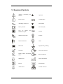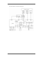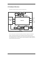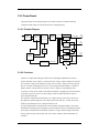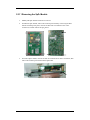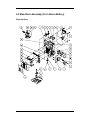
1
Intellectual Property Statement Mindray DS USA, Inc. (hereinafter called Mindray DS) owns the intellectual property rights to this product and this manual. This manual may refer to information protected by copyrights or patents and does not convey any license under the copyright and the patent rights of Mindray DS, nor the rights of others. Mindray DS intends to maintain the contents of this manual as confidential information. Disclosure of the information in this manual in any manner whatsoever without the written permission of Mindray DS is strictly forbidden. Release, amendment, reproduction, distribution, rental, adaption and translation of this manual in any manner whatsoever without the written permission of Mindray DS is strictly forbidden. is a trademark or a registered trademark of Shenzhen Mindray Bio-Medical Electronics Co., Ltd. All third-party trademarks that appear in this manual are used solely for editorial purposes and are the property of their respective owners. Contents of this manual are subject to changes without prior notice. © 2008-2010 Mindray DS USA, Inc. All rights reserved. WARNING z Federal Law (USA) restricts this device to sale by or on the order of a physician. I FOR YOUR NOTES II Preface Manual Purpose This manual provides detailed information about the assembling, dissembling, testing and troubleshooting of the equipment to support effective troubleshooting and repair. It is not intended to be a comprehensive, in-depth explanation of the product architecture or technical implementation. Observance of the manual is a prerequisite for proper equipment maintenance and prevents equipment damage and personnel injury. This manual is based on the maximum configuration; Therefore, some contents may not apply to your monitor. If you have any question, please contact our Customer Service Department. Intended Audience This manual is for biomedical engineers, authorized technicians or service representatives responsible for troubleshooting, repairing and maintaining the monitors. Revision History This manual has a revision number. This revision number changes whenever the manual is updated due to software or technical specification change. Contents of this manual are subject to change without prior notice Revision number: 2.0 Release time: 2010-04 Password A password is required to access the service mode. The service password is 321. 1 FOR YOUR NOTES 2 Contents 1 Safety ................................................................................................................................. 1-1 1.1 Safety Information .......................................................................................................... 1-1 1.1.1 Warnings............................................................................................................. 1-2 1.1.2 Cautions ............................................................................................................. 1-2 1.1.3 Notes .................................................................................................................. 1-2 1.2 Equipment Symbols ........................................................................................................ 1-3 2 Theory of Operation ........................................................................................................ 2-1 2.1 Introduction..................................................................................................................... 2-1 2.2 System Structure ............................................................................................................. 2-1 2.3 Hardware Structure ......................................................................................................... 2-3 2.3.1 Main Board......................................................................................................... 2-4 2.3.2 Power Board....................................................................................................... 2-5 2.3.3 Key&displays Board .......................................................................................... 2-6 2.3.4 Parameter Boards ............................................................................................... 2-7 2.3.5 Recorder ............................................................................................................. 2-9 2.3.6 Bar Code Scanner............................................................................................... 2-9 3 Testing and Maintenance................................................................................................. 3-1 3.1 Introduction..................................................................................................................... 3-1 3.1.1 Recommended Frequency .................................................................................. 3-2 3.2 Visual test ........................................................................................................................ 3-2 3.3 Power-On Test................................................................................................................. 3-3 3.3.1 NIBP Tests.......................................................................................................... 3-3 3.3.2 SpO2 Test............................................................................................................ 3-5 3.3.3 Temp Test ........................................................................................................... 3-6 3.4 Nurse Call Performance Test........................................................................................... 3-7 3.5 Bar Code Scanner Test .................................................................................................... 3-7 3.6 Electrical Safety Tests ..................................................................................................... 3-8 3.6.1 Enclosure Leakage Current Test......................................................................... 3-9 3.6.2 Earth Leakage Current Test.............................................................................. 3-10 3.6.3 Patient Leakage Current Test ........................................................................... 3-10 3.6.4 Patient Auxiliary Leakage Current Test ........................................................... 3-10 3.7 Recorder Check..............................................................................................................3-11 3.8 Program upgrade ............................................................................................................3-11 4 Troubleshooting................................................................................................................ 4-1 4.1 Introduction..................................................................................................................... 4-1 4.2 Part Replacement ............................................................................................................ 4-1 4.3 Monitor Status Check...................................................................................................... 4-1 4.4 Technical Alarm Check ................................................................................................... 4-2 1 4.5 Troubleshooting Guide.................................................................................................... 4-2 4.5.1 Power On/Off Failures ....................................................................................... 4-2 4.5.2 Display Failure ................................................................................................... 4-3 4.5.3 LED Digital Display & Indication Lamp Failure............................................... 4-3 4.5.4 Alarm Problems.................................................................................................. 4-3 4.5.5 Button Failure..................................................................................................... 4-4 4.5.6 Recorder Failures ............................................................................................... 4-4 4.5.7 Interface Failures................................................................................................ 4-5 4.5.8 Power Supply Failures ....................................................................................... 4-5 4.5.9 Network related problems .................................................................................. 4-7 4.5.10 Software Upgrade Problems............................................................................. 4-7 4.5.11 Bar Code Scanner Failures ............................................................................... 4-8 4.5.12 NIBP Measurement Failures ............................................................................ 4-8 4.5.13 SpO2 Measurement Failure.............................................................................. 4-9 4.5.14 Temp Measurement Failures ............................................................................ 4-9 5 Repair and Disassembly .................................................................................................. 5-1 5.1 Tools................................................................................................................................ 5-1 5.2 Preparation for Disassembly ........................................................................................... 5-1 5.3 Disassembly .................................................................................................................... 5-2 5.3.1 Separating the Front and Rear Half of the Monitor............................................ 5-2 5.3.2 Disassembling the Front Housing Assembly...................................................... 5-4 5.3.3 Removing the Main Rack Assembly .................................................................. 5-6 5.3.4 Disassembling NIBP Module ............................................................................. 5-7 5.3.5 Removing the Main Board ................................................................................. 5-8 5.3.6 Removing the Power Board ............................................................................... 5-8 5.3.7 Removing the Battery Assembly........................................................................ 5-9 5.3.8 Removing the Fan and Speaker.......................................................................... 5-9 5.3.9 Removing the Power Socket ............................................................................ 5-10 5.3.10 Removing the Temp Module.......................................................................... 5-10 5.3.11 Removing the SpO2 Module........................................................................... 5-12 6 Parts .................................................................................................................................. 6-1 6.1 Main Unit ........................................................................................................................ 6-1 6.2 Main Rack Assembly (For Lead-acid Batteries) ............................................................. 6-2 6.3 Main Rack Assembly (For Lithium Battery)................................................................... 6-4 6.4 Front housing Assembly.................................................................................................. 6-6 6.5 Rear Housing Assembly.................................................................................................. 6-7 6.6 Lithium Battery Charger Assembly................................................................................. 6-8 6.7 Lead-acid Battery Assembly ........................................................................................... 6-9 6.8 MASIMO SpO2 Board Assembly ................................................................................. 6-10 6.9 Temp Assembly ..............................................................................................................6-11 2 1 Safety 1.1 Safety Information WARNING z Indicates a potential hazard or unsafe practice that, if not avoided, could result in death or serious injury. CAUTION z Indicates a potential hazard or unsafe practice that, if not avoided, could result in minor personal injury or product/property damage. NOTE z Provides application tips or other useful information to ensure better maintenance operation. 1-1 1.1.1 Warnings WARNING z Disassembly and repair of this product should be conducted by Mindray DS authorized personnel only. z To avoid explosion hazard, do not use the equipment in the presence of flammable anesthetics, vapors or liquids. z Follow the applicable waste control regulations to dispose of the package material and keep it out of children’s reach. z The equipment must be connected to a properly installed power outlet with protective earth contacts only. If the installation does not provide a protective earth conductor, disconnect the equipment from the power line and operate it on battery power, if possible. 1.1.2 Cautions CAUTION z Magnetic and electrical fields are capable of interfering with the proper performance of the equipment. For this reason, make sure that all external devices operated in the vicinity of the equipment comply with the relevant EMC requirements. Mobile phones, X-ray equipment or MRI devices are possible sources of interference as they may emit higher levels of electromagnetic radiation. z Before connecting the equipment to the power line, check that the voltage and frequency ratings of the power line are the same as those indicated on the equipment’s label or in this manual. z Protect the equipment from damage caused by drop, impact, strong vibration or other mechanical force during servicing. 1.1.3 Notes NOTE z Refer to Operation Manual for detailed operation and other information. 1-2 1.2 Equipment Symbols Attention manual). (Consulting this Up button Power On/Off Confirm button Alternating current (AC) Down button Battery indicator Pulse Rate (PR) Type CF applied Defibrillator-proof part. Neonate NIBP start/stop button Pediatric Patient Information Adult Main menu Equipotential grounding Set alarms Nurse Call connector Display Tabular Trends/Pleth Wave RS-232 connector NIBP interval Date of manufacture Record Serial number Alarm Silence Network connector 1-3 FOR YOUR NOTES 1-4 2 Theory of Operation 2.1 Introduction The monitor is intended for monitoring the patient’s vital signs including non-invasive blood pressure (NIBP), pulse oxygen saturation (SpO2) and pulse rate (PR) for single adult, paediatric and neonatal patient. It is also designed to monitor the temperature Temp) for single adult and paediatric patient. 2.2 System Structure The whole system consists of mechanical parts, hardware and software, as follows: System Mechanical Hardware Software Main unit Main board System software Recorder Power board Parameter software Battery chamber Key&display Upgrade software Temp module charmber Parameter boards Print software Recorder board Gateway software Barcode scanner support Barcode scanner 2-1 The system’s PCBAs are connected as shown below: 2-2 2.3 Hardware Structure The monitor’s hardware structure is shown in the figure below. SpO2 module TEMP module NIBP module Isolation power board * Communication/p ower supply Communication/p ower supply LED & KEY Key&display board Ethernet RS232 Main board LCD NurseCall Power supply Speaker Battery Recorder Fan Power board AC VS-800 * Mindray SpO2 module does not require the isolation power board. The core of the system is the main board which provides power supply for all parameter modules. The parameter modules directly communicate with the main board, and the measurements and status of all modules are processed by the main board and then displayed on the key&display board. The main board also controls communication with the speaker, the recorder and all the external connectors. 2-3 2.3.1 Main Board The main board provides resources and supports for the overall system. It controls LCD, LED, keyboard, speaker and recorder. It also enables to communicate with parameter modules and connectors. 2.3.1.1 Principle Diagram Watchdog Ethernet SPI Nurse Call Serial port 0 CPU Speaker E 2 PROM RTC PHY RTL8201 RS232 RS232 IC Serial port 1: NIBP Audio process circuit Serial port 2: SpO2 SDRAM Flash Serial port 3: Temp FPGA Serial port 4: Recorder 1 .5 V Linear power 3.3V 5.0V 12V LCD LED KEY 2.3.1.2 Function Description The main board communicates with all the parameter modules and the recorder through FPGA extended serial port. The main board supplies information through FPGA for the key&display board to display; it detects the keys and implements user interface. The main board controls the alarm indicator via FPGA and the signal wire is adapted from key&display board. The main board controls the speaker to give audible alarm, key tones and Pitch Tone. The main board provides nurse call connector, network connector and R232 connector. The real-time clock is implemented by the RTC chip. The RT clock is powered according to the priority of AC mains, battery, and button cell on the main board. This ensures the normal working status of the clock in the event that AC mains and batteries are not available. SDRAM is responsible for storing data temporarily and running programs. Flash serves as the system memory and trend data memory whereas EEPROM services as the device configuration memory. 2-4 2.3.2 Power Board The power board converts the input power (AC mains or battery) to different working voltages for other boards; it also has the function of charging battery. 2.3.2.1 Principle Diagram AC input EMI filter Rectifer & filter Flyback converter Rectifier & filter 16.8V DC/DC converter OVP&OCP 5V output DC/DC converter Charging circuit Current detection PWM controller Battery 3.3V output DC/DC converter Coupler feedback & isolation circuit OVP&OPP Switch circuit 12V output OVP&OCP PCON 2.3.2.2 Functions After the AC input reaches the power board, it flows through the EMI filter circuit and rectifier and filter circuit. Then it is converted to a DC voltage, which is further converted to the 16.8V DC voltage by the Flyback converter. The 16.8V DC voltage is the main input of DC/AC converter and charging circuit; it is used to charge the lithium battery or lead-acid battery, and also converted to 12V, 5V and 3.3V DC voltage by corresponding circuit conversion. In case the AC input is unavailable, the battery can supply power for the DC/DC converters to get 12V, 5V and 3.3V DC voltages, which are under the control of device poweron/poweroff signal. The 16.8V DC output is protected against over-voltage and over-power, the 12V and 3.3V DC outputs are protected against over-voltage, short-circuit and over –current, the 5V DC output is protected against over-voltage and short-circuit. Two power boards are developed for the lead-acid battery and lithium battery. Each board demonstrates the battery types it supports via the main board connector, facilitating the main unit to process information such as battery capacities. The power board charges the battery merely under AC input. The monitor runs on AC mains if both AC mains and battery are available. 2-5 2.3.3 Key&displays Board The key&displays board provides the user’s interface. The LCD module, 7-segment digital display, LED indication lamp and keys are integrated on the board. 2.3.3.1 Principle Diagram LCD signal FSTN LCD module LED LED&KEY CPLD 3.3V disable ADV 3.3V Start-up circuit detection Key matrix Switch VSB 2.3.3.2 Functions The LCD module has the function of adjusting the contrast and brightness in 10 levels, displaying menus, trend data and Pleth waveform. The 7-segment digit displays are used to display systolic pressure, diastolic pressure, mean pressure/cuff pressure, SpO2, PR, Temp and so forth. The AC indicator is driven by the ADV output from the power board whilst the working status indicator (built in the Power On/Off key) is driven by 3.3V voltage. The battery indicator is jointly controlled by the flash control signal, ADV signal and /BC signal. The keypad consists of the power ON/OFF key and the other 11 functional keys. 2-6 2.3.4 Parameter Boards 2.3.4.1 SpO2 Module The principle diagram of SpO2 module is shown below: /RST Isolated Serial In/Output Port WATCHDOG WDI DRAM DRIVE DAC CPU FLASH LED DRIVE CIRCUITRY 4KV Isolated Power Supply HOST +12V +3.3V +5V -5V SENSOR A/D CONVERTER GAIN CONTROL CIRCUITRY OFFSET DAC PROGRAMMABLE GAIN CIRCUITRY OFFSET AMPLIFIER The SpO2 sensor collects the red and infrared light signal transmitting through the finger or toe which is pulsing and process the collected signal to get the measured result. The drive circuit of the LED and the gain of the amplifying circuit should be controlled according to the perfusions and transmittances of the tested objects. 2-7 2.3.4.2 NIBP Module The principle diagram of NIBP module is shown below: CUFF PRESSURE SENSOR FOR PROTECT PRESSURE SIGNAL AMPLIFIED CIRCUITS FOR PROTECT OVER PRESSURE PROTECT CIRCUIT ASYNCHRONOUS SERIAL COMMUNICATION WATCHDO G CPU PRESSURE SENSOR Windpipe Valve and Air Pump PRESSURE SIGNAL AMPLIFIED CIRCUITS PRESSURE SIGNAL A/D CONVERTER MOTOR CONTROL FEEDBACK SIGNAL PUMP AND VALVES CONTROLED CIRCUITS FLASH DRAM The NIBP is measured based on the pulse vibration principle. Inflate the cuff which is on the forearm till the cuff pressure blocks the arterial blood, and then deflate the cuff according to a specified algorithm. While the cuff pressure is decreasing, the arterial blood has pulses, which are sensed by the pressure transducer in the cuff. Consequently, the pressure transducer connected with the windpipe of the cuff, generates a pulsation signal, which is then processed by the NIBP module to get the NIBP value. NIBP values are based on the oscillometric method of noninvasive blood pressure measurement and correspond to comparisons with auscultative values (applied to adults and pediatrics elder than 3 years) and intra-arterial values (applied to neonates and pediatrics younger than 3 years) within ANSI/AAMI SP10 Standards for accuracy (a mean difference of ± 5 mmHg, and a standard deviation of < 8 mmHg). 2-8 2.3.4.3 Temp Module The principle diagram of Temp module is shown below: Normally, the sensor used for measuring temperature is a thermistor. The resistance of a given thermistor is nonlinearly relative to the temperature. Thus, the resistance of a thermistor can be conversed into temperature. By applying given field current to the thermistor, its resistance can be easily obtained by measuring the voltage on the thermistor. 2.3.5 Recorder The recorder receives data from the main board and then sends them to the thermal printhead for printing. The recorder has a hardkey(starting/stopping recordings) and a green LED on its front. 2.3.6 Bar Code Scanner The bar code scanner enables to read the one-dimensional and two-dimensional bar codes, simplifying patient admit. The bar code scanner communicates with the monitor and gets power supply to the power source via the serial ports. The scanner’s serial port is defined as follows: PIN Definition 2 Barcode_RX 3 Barcode_TX 5 GND 9 VCC(5VDC) 2-9 The monitor’s serial port is defined as follows: PIN Definition 2 DPM 3_TX 3 DPM 3_RX 5 GND 9 VCC(5VDC) Basic settings of the bar code scanner are listed in the table below: Bar code scanner Factory default Baud Rate 9600 9600 Data Bits 8 8 Stop Bits 1 1 Host Parameters Calibration bit 0 0 Handshaking None None Beeper Tone Medium Medium Beeper Volume Medium High Trigger Mode Level Auto Aim Parameter Scanning Disable Enable Prefix Value 7013 <CR><LF> 7013 <CR><LF> Suffix 1 Value Suffix 2 Value 7013 <CR><LF> 7013 <CR><LF> Scan Data Transmission Format <PREFIX><DATA><SUFFIX 1><SUFFIX 2> Data only User Parameters Data Format You shall program the bar code scanner to perform various functions. To change parameter settings, scan the following bar codes in sequence. 1. Set Default Parameter 2-10 2. Beeper Volume 3. Trigger Mode 4. Scan Data Transmission Format 5. Disable Parameter Scanning 2-11 FOR YOUR NOTES 2-12 3 Testing and Maintenance 3.1 Introduction To ensure the monitor always functions normally, qualified service personnel should perform regular inspection, maintenance and test. This chapter provides a checklist of the testing procedures for the monitor with recommended test equipment and frequency. The service personnel should perform the testing and maintenance procedures as required and use appropriate test equipment. The testing procedures provided in this chapter are intended to verify that the monitor meets the performance specifications. If the monitor or a module fails to perform as specified in any test, repairs or replacement must be done to correct the problem. If the problem persists, contact our Customer Service Department. CAUTION z All tests should be performed by qualified service personnel only. z Care should be taken to change the settings in the [MAINTAIN] menu to avoid loss of data. z Service personnel should acquaint themselves with the test tools and make sure that test tools and cables are applicable. 3-1 3.1.1 Recommended Frequency Check/Maintenance Item Frequency Visual test When first installed or after reinstalled. Power on test 1. When first installed or after reinstalled. 2. Following any maintenance or the replacement of any main unit parts. NIBP tests Accuracy test Leakage test IBP tests 1. If the user suspects that the measurement is incorrect. Calibration 2. Following any repairs or replacement of respective module. Performance test 3. At least once every two years. Pressure calibration SpO2 test / Temp test / Analog output test / Bar code scanner test / If the user suspects that analog output or bar code scanner is abnormal. Electrical safety tests Enclosure leakage current test 1. Following any repair or replacement of the power module. Earth leakage current test 2. At least once every two years. Patient leakage current test Patient auxiliary current test Recorder check / Following any repair or replacement of the recorder. 3.2 Visual test Inspect the equipment for obvious signs of damage. The test is passed if the equipment has no obvious signs of damage. Follow these guidelines when inspecting the equipment: Carefully inspect the case, the display screen and the buttons for physical damage. Inspect all external connections for loose connectors, bent pins or frayed cables. Inspect all connectors on the equipment for loose connectors or bent pins. Make sure that the labels on the equipment are clearly legible. 3-2 3.3 Power-On Test This test is to verify that the monitor can power up correctly. The test is passed if the monitor starts up by following this procedure: 1. Insert the lead-acid batteries or lithium battery in the battery compartment and connect the monitor to the AC mains; the AC mains LED and battery LED light. 2. Press the Power On/Off button to turn on the monitor. The operating status LED which is built in the Power On/Off button lights up. 3. The system gives a beep indicating the self test related to alarm sounds is passed and all the LEDs on the front panel light up. At the same time, the technical alarm lamp turns yellow, and then turns off, indicating that the self test related to alarm lamps is passed. 4. The start-up screen disappears; the monitor enters the main screen and start-up is finished. 3.3.1 NIBP Tests NIBP Accuracy test Tools required: T-shape connector Appropriating tubing Balloon pump Metal Vessel with volume 500 ± 25 ml Reference manometer with accuracy 1 mmHg Follow this procedure to perform the test: 1. Connect the equipment as shown above. Monitor NIBP cuff connector Manometer Tubing Metal vessel Balloon pump 3-3 2. Before inflating the metal vessel, the reading of the manometer should be 0. If not, disconnect the airway and reconnect it until the readings is 0. 3. Press the MENU key; select [MAINTAIN >>]→[NIBP CALIBRATE] to start NIBP calibration. Compare the manometer values with the displayed values. The difference should be no greater than ±3mmHg (±0.4kPa). 4. Raise the pressure in the metal vessel to 50 mmHg with the balloon pump. Repeat step3. 5. Raise the pressure in the metal vessel to 200 mmHg with the balloon pump. Repeat step 3. Contact our service personnel if the difference between any manometer value and the displayed value is greater than ±3 mmHg. NOTE z You can use an NIBP simulator to replace the balloon pump and the reference manometer to perform the test. NIBP Leakage Test Tools required: NIBP cuff for adult patient Approprating tubing Cylinder Follow this procedure to perform the test: 1. Set [PATIENT TYPE] to [ADU]. 2. Connect the NIBP cuff with the NIBP connector on the monitor. 3. Apply the cuff to the cylinder as shown below. Cylinder Monitor NIBP cuff connector Air tubing Cuff 4. Press the MENU key; select [MAINTAIN >>]→ [NIBP LEAK TEST]. 5. The cuff automatically deflates in 20s, which means NIBP leakage test is completed. 6. If the system does not leak, no message will be displayed in the technical alarm area/prompt area. If it leaks, the message [PNEUMATIC LEAK] will be displayed. In this case, check for loose connection and perform the test again. Please contact our service personnel if the NIBP test fails. 3-4 3.3.2 SpO2 Test Tool Required: SpO2 simulator. For the monitor equipped with Mindray DS SpO2 module, BIO-TEK Index-2 SpO2 simulator is recommended. For the monitor equipped with Nellcor SpO2 module, SRC-MAX SpO2 simulator is recommended. For the monitor equipped with Masimo SpO2 module, BIO-TEK Index-2 SpO2 simulator is recommended. 3.3.2.1 SpO2 Test under Normal Condition 1. Connect the SpO2 simulator to the SpO2 sensor. 2. Select the model and the manufacturer of the SpO2 module under test, and then configure the SpO2 simulator as follows: SpO2 96%; PR 80 bpm. 3. The displayed SpO2 and PR values should be within the ranges listed below. 3.3.2.2 SpO2 Test in Motion Mode 1. Connect the SpO2 simulator to the SpO2 sensor. 2. Select the model and the manufacturer of the SpO2 module under test; take measurement in the motion mode preset by the SpO2 simulator. 3. The displayed SpO2 and PR values should be within the ranges listed below. Manufacturer SpO2 sensor SpO2 PR (bpm) 512B, 512 D, 512E, 512G, 512F, 512H, 518B, ES-3212-9/envitec, MAX-A, MAX-P, Mindray DS MAX-I, DS-100A, OXI-P/I, 520A, 520P, 96%±2% 80±3 520I, 2211-1 Envite, 2211-2 Envite, 2211-5 Envite 520N, MAX-N, OXI-A/N, 2211-6 Envite 3-5 96%±3% Manufacturer SpO2 sensor SpO2 LNCS-NeoPt-L, LNCS Neo-L 96%±3% (without motion) 96%±3% (with motion) Masimo LNCS Inf-L , LNCS-Pdt, LNCS-Adtx ,LNCS DC-I,LNCS DC-I Pt Nellcor PR (bpm) 96%±2% (without motion) 80±3 bpm (without motion) 80±5 bpm (with motion) 96%±3% (with motion) MAX-A, MAX-P, MAX-I, 96%±2% DS-100A, OXI-A/N (Adult), OXI-P/I, MAX-N 96%±3% OXI-A/N (Neonate) 96%±4% 80±3 bpm NOTE z The SpO2 simulator can only be used to verify that the pulse oximeter operates properly. It cannot be used to verify the accuracy of the pulse oximeter or the SpO2 sensor. To verify the accuracy, clinical tests are required. Please contact our service personnel if the SpO2 test fails. 3.3.3 Temp Test Tool required: thermostatic oil tank, HART 7102 recommended. 1. Set the temperature of the oil tank to 37℃ and conduct the test after the temperature stabilizes. 2. Set the [TEMP TYPE] to [MONITOR]. Remove the Temp probe from the probe sheath and then put it into the oil tank. 3. Wait till the Temp value displayed on the monitor stabilizes. Verify that the displayed value is 37±0.2 ℃. Please contact our service personnel if the Temp test fails. 3-6 3.4 Nurse Call Performance Test Tools required: Multimeter 1. Connect the nurse call cable to the analog output connector. 2. Trigger a psychological alarm or a technical alarm. 3. Select [NURSE CALL>>] in the [MAINTAIN] menu. In the [NURSE CALL] menu, select [ALM LEV] and [ALM TYPE]; set [CONTACT TYPE] to [NORMAL OPEN]. 4. In the [NURSE CALL >>] menu, set [SIGNAL TYPE] to [PULSE]. Trigger an alarm and measure the contact output with the multimeter. The output should be square waves with an interval of 1s, 5. In the [NURSE CALL >>] menu, set [SIGNAL TYPE] to [CONTINUUM]. Trigger an alarm and measure the contact output with the multimeter. The output should be continuous high level. Please contact our service personnel if the nurse call test fails. 3.5 Bar Code Scanner Test Tools required: None 1. Aim the bar code scanner at the target bar code. Adjust the field of view to capture the bar code. 2. Hold the trigger until the bar code scanner gives a beep, indicating the bar code is successfully decoded. Meanwhile, the indication lamp turns to green and scanned characters are displayed on the monitor. Please contact our service personnel if the bar code scanner fails to work normally. 3-7 3.6 Electrical Safety Tests WARNING z Electrical safety tests are a proven means of verifying the electrical safety of the monitor. They are intended for determining potential electrical hazards. Failure to find out these hazards timely may cause personnel injury. z Commercialy available test equipment such as safety analyzer can be used for electrical safety tests. Be sure that the test equipment can be safely and reliably used with the monitor before use. The service personnel should acquaint themselves with the use of the test eqipment. z Electrical safety tests should meet the requiremnets of the latest editions of EN 60601-1 and UL60601. z These electrical safety tests do not supercede local requiremnets. z All devices using the AC mains and connected to medical equipment within patient environments must meet the requiremnets of the IEC 60601-1 medical electrical systems standard and should be put under electrical safety tests at the frequency recommended for the monitor. Electrical safety tests are intended to timely check the potential electrical hazards to the patient, operator or service personnel arising from the equipment. Electrical safety test should be performed under normal ambient conditions of temperature, humidity and atmospheric pressure. The electrical safety test plan described hereunder takes 601 safety analyzer as an example. Different safety analyzers may be used in different areas. Be sure to choose applicable test plan. 3-8 Connection of the equipments is shown below: Tools required: Safety analyzer Isolation transformer 3.6.1 Enclosure Leakage Current Test 1. Connect the 601 safety analyzer to an AC power supply (264V, 60 Hz). 2. Connect SUM terminal of the applied part connection apparatus to RA input terminal of 601 safety analyzer, another terminal to the applied part of EUT. 3. Connect the EUT to the 601 analyzer’s auxiliary output connector by using a power cord. 4. Attach on end of the red lead to the red input terminal of the analyzer, and the other end to tinsel over the enclosure of the EUT. 5. Power on the 601 safety analyzer and then press the “5-Enclosure leakage” button on the analyzer’s panel to enter the enclosure leakage test screen. 6. Under normal condition, the enclosure leakage current should be no greater than 100µA. Under single fault condition, it should be no greater than 300µA. 3-9 3.6.2 Earth Leakage Current Test 1. Connect the 601 safety analyzer to an AC power supply (264V, 60 Hz). 2. Connect the SUM terminal of the applied part connection apparatus to RA input terminal of 601 safety analyzer, another terminal to the applied part of EUT. 3. Connect the EUT to the 601 analyzer’s auxiliary output connector by using a power cord. 4. Power on the 601 safety analyzer and then press the “4-Earth leakage” button on the analyzer’s panel to enter the earth leakage test screen. 5. Under normal condition, the earth leakage current should be no greater than 300µA. Under single fault condition, it should be no greater than 1000 µA. 3.6.3 Patient Leakage Current Test 1. Connect the 60 safety analyzer to an AC source (264V, 60Hz). 2. Connect the SUM terminal of the applied part connection apparatus to RA input terminal of 601 safety analyzer, another terminal to the applied part of EUT. 3. Connect the EUT to the 601 analyzer’s auxiliary output connector by using a power cord. 4. Power on the 601 safety analyzer and then press the “6-Patient leakage” on the 601 analyzer’s panel. 5. Repeatedly press the “APPLIED PART” button to measure AC and DC leakage alternatively. DC leakage reading is followed by “DC”. 6. Under normal status, the patient leakage current should be no greater than 10 µA. Under single fault condition, it should be no greater than 50µA. 3.6.4 Patient Auxiliary Leakage Current Test 1. Connect the 601 safety analyzer to an AC source (264V, 60Hz). 2. Connect the equipment under test (EUT) to the analyzer’s auxiliary output connector by using a power cord. 3. Connect the sensors of the applied part to the applied part connection apparatus, whose RA-P terminal is connected to 601 safety analyzer’s RA terminal and SUM terminal to 601 safety analyzer’s LA terminal. RA terminal is switched on. 3-10 4. Power on the 601 safety analyzer and then press the “8-Patient Auxiliary Current Test” button on the analyzer’s panel to enter the patient auxiliary current test screen. 5. Repeatedly press the “APPLIED PART” button to measure AC and DC leakage alternatively. DC leakage reading is followed by “DC”. 6. Under normal status, the patient auxiliary leakage current should be no greater than 10 µA. Under single fault condition, it should be no greater than 50µA. Please contact our service personnel if the electrical safety test fails. 3.7 Recorder Check 1. Print SpO2 Pleth waveforms. The recorder should print correctly and printout should be clear. 2. Set the recorder to some problems such as out of paper, paper jam and etc, the monitor should give corresponding prompt messages. After the problem is removed, the recorder should be able to work correctly. 3. Set the recorder to print trend data. Check that the recorder can give printouts accordingly. Please contact our service personnel if the recorder test fails. 3.8 Program upgrade You can upgrade the monitor by downloading the upgrade software through network. At the same tine, you can view the upgrade status log. The upgrade software can directly run on a portable PC or desktop PC. Through the network or by connecting the monitor to a PC via a network cable, you can upgrade the following programs: Bootstrap program System program Bar code recognition configuration Multiligual library General configurations (including passwords, company logo) System functional configuration FPGA program Parameter module programs: SpO2 module (Mindray DS), NIBP module and Temp module. Please refer to help and instructions for program upgrade for details. 3-11 CAUTION z Disconnect the monitor from the patient and make sure the important date are saved before upgrade. z Do not shut down or power off the equipment when upgrading the bootstrap program. Otherwsie, it may cause the equipemnt to break down. z Programs upgrade should be performed by qualified service personnel only. NOTE z After upgrading the boot program, re-upgrade the system program and other programs to ensure compatibility. z Make sure the version of the upgrade package is your desired one. If you want to obtain the latest upgrade package, contact our Customer Service Department. 3-12 4 Troubleshooting 4.1 Introduction In this chapter, monitor problems are listed along with possible causes and recommended corrective actions. Refer to the tables to check the monitor, identify and eliminate the troubles. The troubles we list here are frequently arisen difficulties and the actions were recommended can correct most problems, but not all of them. For more information on troubleshooting, please contact our Customer Service Department. 4.2 Part Replacement Printed circuit boards (PCBs), major parts and components in the monitor are replaceable. Once you isolate a PCB you suspect defective, follow the instruction in 5 Repair and Disassembly to replace the PCB with a known good one and check that the trouble disappear or the monitor passes all performance tests. If the trouble remains, exchange the replacement PCB with the original suspicious PCB and continue troubleshooting as directed in this chapter. Defective PCB can be sent to us for repair. To obtain information on replacement parts or order them, please refer to 6 Parts. 4.3 Monitor Status Check Some troubleshooting tasks may require you to identify the hardware version and status of your monitor. 1. To view system software version and FPGA version, select [MENU] → [MAINTAIN>>] → [VERSION]. 2. To view the monitor’s total runtime, select [MENU] → [MAINTAIN>>] → [VERSION]→[TOTAL RUN TIME>>]. 3. To view modules’ software version, select [MENU] → [MAINTAIN>>]→ [VERSION] →[MODULE VERSION>>]. 4-1 4.4 Technical Alarm Check Check whether technical alarm message is displayed on the monitor before troubleshooting. If an alarm message is presented, eliminate the technical alarm first and troubleshoot in accordance with the following instructions. For further information on technical alarm message, possible cause and corrective action, please refer to the monitor’s Operation Manual. 4.5 Troubleshooting Guide 4.5.1 Power On/Off Failures Symptoms Possible Cause Corrective Actions The monitor fails to start. AC LED or battery LED does not light AC mains not connected or battery too low. Check whether AC mains is properly connected or battery capacity is sufficient Power supply protection Refer to 4.5.8Power Supply Failures. Cables defective or poorly connected 1. Check whether the cables from power switch & LED board to button board, button board to main board, and power module to main board are correctly connected. 2. Check whether cables and connectors are damaged. Power switch & LED board defective Replace the power switch & LED board Power module defective Replace the power module Main board Defective Replace the main board 4-2 4.5.2 Display Failure Symptoms Possible Cause Corrective Actions The display is black or blank, but the monitor still works correctly. Cables defective or poorly connected 1. Check whether cables from the display to the main board are correctly connected. 2. Check whether cables and connectors are damaged. Backlight defective Replace LCD. LCD defective Replace LCD. FPGA error Update or upgrade FPGA. Cables defective or poorly connected 1. Check whether the cable from the display to the main board is correctly connected. 2. Check whether the cables and connectors are damaged. Images overlapped or distorted 4.5.3 LED Digital Display & Indication Lamp Failure Symptoms Possible Cause Corrective Actions LED digital display or indication lamp display abnormally. Signal wires damaged 1. Check whether LED signal wires are correctly connected 2. Check whether cables and connectors are damaged LED digital display or indication lamp damaged Replace LED digital display or indication lamp 4.5.4 Alarm Problems Symptoms Possible Cause Corrective Actions The alarm lamp is not light or extinguished but alarm sound is issued Cables defective or poorly connected 1. Check whether cables from alarm LED board to button board and button board to main board are properly connected. 2. Check that connecting cables and connectors are not damaged. Alarm LED board failure Replace the alarm LED board. Button board failure Replace the button board. Main board failure Replace the main board. 4-3 Symptoms Possible Cause Corrective Actions No alarm sound is issued but alarm lamp lights properly Audio alarm disabled Select [MENU] → [MAINTAIN>>] → [USER MAINTAIN >>] → enter the required password. In the pop-up menu, set the [MIN ALARM VOL] to a value other than zero. Cable defective or poorly connected 1. Check whether the cable between speaker and main board is properly connected. 2. Check whether the connecting cables and connectors are damaged. Audio program error identified in the system program Upgrade system programs Speaker failure Replace the speaker Main board failure Replace the main board 4.5.5 Button Failure Symptoms Possible Cause Corrective Actions Buttons do not work Cables defective or poorly connected 1. Check whether the cable between button board and main board is properly connected 2. Check whether connecting cables and connectors are damaged Button board failure Replace button board 4.5.6 Recorder Failures Symptoms Possible Cause Corrective Action No printout Recorder module disabled 1. Check whether the recorder status LED is on 2. If yes, please reset the recorder. Otherwise, check for other possible causes. Paper reversely installed Re-install the paper roll Cable defective or poorly connected 1. Check whether the cable between recorder and main board is appropriately connected 2. Check whether connecting cables and connectors are damaged Recorder power supply failure Check if the power module outputs 5V DC and 12V DC correctly. Recorder failure Replace the recorder 4-4 Symptoms Possible Cause Corrective Action Poor print quality or paper not feeding properly Paper roll not properly installed Stop the recorder and re-install the paper roll Dirty thermal print head 1. Check the thermal print head and the paper roller for foreign matter. 2. Clean the thermal print head with an appropriate detergent Recorder failure Replace the recorder 4.5.7 Interface Failures Symptoms Possible Cause Corrective Action No nurse call signals are issued Incorrect function settings Select [MENU] → [MAINTAIN>>] → [NURSE CALL >>] → select desired nurse call output. Main board failure Replace the main board Bar code scanner unable to be used Bar code scanner failure Please refer to 4.5.11Bar Code Scanner Failures. Serial port failure Replace the main board 4.5.8 Power Supply Failures Symptoms Possible Cause Corrective Action Fluctuating battery voltage Battery failure Replace battery Cable defective or poorly connected 1. Check whether the cable between battery interface board and power module is correctly connected. 2. Check whether cables and connectors are damaged Power board failure Replace the power board Battery failure Replace battery Cable defective or poorly connected 1. Check whether the cable between battery interface board and the power module is properly connected 2. Check whether the connecting cables and connectors are damaged Power board failure Replace the power board Battery fails to be fully charged 4-5 Symptoms Possible Cause Corrective Action Battery unable to be recharged Battery damaged Replace battery and recharge the replacement battery. If the replacement battery can be recharged, the original one fails. Cable defective or poorly connected 1. Check whether the cable between battery interface board and the power module is properly connected 2. Check whether the connecting cables and connectors are damaged Power board failure Replace the power board 1. Power supply protection 2. Power board failure 1. Turn off the monitor then restart it. 2. If the problem remains, disconnect the AC mains for 5 s and reconnect it, then restart the monitor. 3. If the problem still remains, replace power board. No +3.3 V output No +5.0 V output No +12 V output NOTE z When the power module has a failure, it may cause problems to other components, e.g. the monitor suddenly shuts downs during the start-up, as the power module may have a power supply protection. In this case, troubleshoot the power module as per the procedure described in the table above. z Parameter module, recorder and bar code scanner are powered by the power module. In the event that a componet malfunctions, check if the operating voltage is correct. Refer to 2 Theory of Operation for the operating voltage and measurement point of each component. 4-6 4.5.9 Network related problems Symptoms Possible Cause Corrective Actions The monitor cannot be connected to the CMS. No connection to LAN 1. Confirm whether the cables and connectors are in good condition and whether the network is correctly connected. 2. Check whether the hub or switch facilities is correctly configured Frequent dropouts and network disconnections Improper LAN cable connection Check LAN cable connection. LAN cable shall not be longer than 50 m. Incorrect IP address configuration Check for IP address conflict. Reconfigure IP address. 4.5.10 Software Upgrade Problems Symptoms Possible Cause Corrective Actions Bootstrap upgrade fails Power failure or unintended power off during bootstrap upgrade Return the main board to the factory for repair Program upgrade fails Incorrect network connection 1. Check that network connector on the monitor is used. 2. Make sure that the hub or the switcher runs normally. Check whether net cables are of the right type and have been connected correctly. Wrong upgrade package has been downloaded Upgrade package shall be .mup files. Select desired package according to the program you want to upgrade. Incorrect IP address configuration Configure a fixed IP address in range C as specified for the monitor. We recommend not to upgrade a program when the monitor is connected to a network with multiples PCs. 4-7 4.5.11 Bar Code Scanner Failures Symptoms Possible Cause Corrective Actions Bar code scanner does not work Bar code scanner not powered on Select [MAINTAIN >>] → [USER MAINTAIN >>] → enter required user password; set [BARCODE POWER] to [ON] in the pop-up menu to switch on the bar code scanner. Incorrect interface cables used Replace interface cables Loose Interface cables Make sure that interface cables are fixed Bar code scanner not programmed based on bar code categories Make sure to program the bar code scanner so that it can decode the bar codes of specified types. Unreadable bar code Make sure the bar code is flawless and check if bar codes of the same type can be decoded. Scanner and bar code at improper distance and angle Aim the scanner at the bar code and adjust the distance between the scanner and the bar code. The monitor’s bar code recognition configuration does not meet the format of the target bar code. Download correct bar code recognition configuration for the monitor. Scanner serial port output incorrectly set Configure the scanner’s serial port output according to the host serial port settings. Bar code scanner cannot decode the target bar codes Scanned characters incorrectly displayed on the monitor 4.5.12 NIBP Measurement Failures Symptoms Possible Cause Corrective Actions Unable to start NIBP measurement Cables detective Check whether cables between NIBP module and the main board are in good condition. Main board failure Replace the main board. Cuff inflation/deflation failure Pump or valve damaged Replace NIBP module. Air tubing occluded Replace the air tubing. 4-8 4.5.13 SpO2 Measurement Failure Symptoms Possible Cause Corrective Actions Unable to measure SpO2 SpO2 sensor failure Replace the SpO2 sensor. Cables defective Check whether the cable between SpO2 module and the main board is in good condition. SpO2 module failure Replace SpO2 module. Main board failure Replace the main board. 4.5.14 Temp Measurement Failures Symptoms Possible Cause Corrective Actions Unable to measure patient temperature. Temp probe damaged Replace the Temp probe. Cables detective Check whether the cable between Temp module and the main board is in good condition. Main board failure Replace the main board 4-9 FOR YOUR NOTES 4-10 5 Repair and Disassembly 5.1 Tools During disassembly and replacement, the following tools may be required: Philips screwdrivers Wire cutters Sharp nose pliers M6 spanner 5.2 Preparation for Disassembly Before disassembling the monitor, stop monitoring the patients, turn off the monitor and disconnect all the accessories and peripheral devices. Caution z Before disassembling the monitor, be sure to eliminate the static charges first. When disassembling the parts labeled with static-sensitive symbols, make sure you are wearing electrostatic discharge protection such as antistatic wristband or gloves to avoid damaging the equipment. z Properly connect the cables or wires when reassembling the monitor to avoid short circuit. z When assembling the monitor, be sure to select proper screws. If an unfit screw is tightened by force, the monitor may be damaged and the screw or the part may fall off during use to cause unpredictable damage or human injury. z Be sure to follow the correct sequence to disassemle the monitor. Otherwise, the monitor may be damaged permanently. z Be sure to disconnect all the cables before disassembling any parts. Be sure not to damage any cables or connectors. z Place the screws and parts removed from the monitor properly, avoiding avoid falling off, tarnishing or losing the parts. 5-1 5.3 Disassembly 5.3.1 Separating the Front and Rear Half of the Monitor 1. If the monitor is configured with Temp module, Unscrew the two M3×6 crosshead screws with a screwdriver as shown in the figure below. Disconnect the wires from the PCBA as shown in the figure below. Unscrew the four M3×20 crosshead screws with a screwdriver(102) as shown in the figure below. 5-2 2. If the device is not equipped with a Temp module, Unscrew the four M3×20 crosshead screws directly with a screwdriver(102) as shown in the figure below. NOTE z When separating the front and the rear part, use screwdriver(102) instead of screwdriver (107) to unscrew the four M3×20 crosshead screws. 3. Release the clips on the front and rear housings; cut the cable tie of the LCD signal wire with a wire cutter; disconnect the cables and air tubing connecting the front and the rear housings; and then separate the front and the rear housings. Clip 5-3 NOTE z Exercise care when separating the front and the rear housings. Be sure not to damage the cables and connectors. 5.3.2 Disassembling the Front Housing Assembly 1. Unscrew the six M3×6 crosshead screws with a screwdriver and remove the button board. 2. Unscrew the four M3×8 crosshead screws with a screwdriver; disconnect the flexible cables on the button board; and then remove the LCD. 5-4 3. Unscrew the three M3×6 crosshead screws with a screwdriver and take out the SpO2 rack. 4. Unscrew the M3×6 screw with a screwdriver and take out the SpO2 module. Mindray DS SpO2 module 5. Masimo SpO2 module Nellcor SpO2 module Unscrew the plastic nut and take out the SpO2 signal cable. 5-5 5.3.3 Removing the Main Rack Assembly 1. Unscrew the two M3×6 crosshead screws with a screwdriver and take out the recorder by unclenching the clips. 2. Remove the cables from the recorder and unscrew the M3×6 crosshead screw with a screw driver. 3. Unscrew the five M3×6 crosshead screws with a screwdriver and take out the main rack assembly. 5-6 4. Provided that the device is configured with a Temp module, unscrew the three PT3×8 tapping screws with a screwdriver and then remove the Temp module. 5.3.4 Disassembling NIBP Module 1. Cut the cable tie with a wire cutter 2. Unscrew the three M3×6 crosshead screws with a screwdriver and take out the NIBP rack. 5-7 3. Unscrew the four M3×6 crosshead screws with a screwdriver and take out the NIBP module. 5.3.5 Removing the Main Board Disconnect all the cables connecting the main board and then take out the main board by unscrewing the four M3×6 crosshead screws with a screwdriver. 5.3.6 Removing the Power Board Pull out the cables that connect the power board and remove the power board by unscrewing the three M3×6 crosshead screws with a screwdriver. 5-8 5.3.7 Removing the Battery Assembly 1. If the monitor is equipped with the lead-acid battery assembly, unscrew the four M3×8 crosshead screws with a screwdriver. 2. If the monitor is equipped with the lithium battery assembly, unscrew the three M3×6 crosshead screws with a screwdriver. 5.3.8 Removing the Fan and Speaker Cut the cable ties on the fan, speaker and the main rack; remove the fan cushion; unscrew the three M3×15 crosshead screws with a screwdriver and remove the fan. The speaker can be removed from the main rack directly. 5-9 5.3.9 Removing the Power Socket 1. Remove the nut securing the grounding post with a spanner and take out the grounding terminal of the power socket. 2. Unscrew the two M3×8 crosshead screws with a screwdriver and remove the power socket. 5.3.10 Removing the Temp Module 1. Remove the Temp probe assembly first. 5-10 2. Unscrew the two M3×6 cross head screws with a screwdriver and take out the cover plate. 3. Unscrew the four M3×6 crosshead screws with a screwdriver and remove the Temp module main board. 5-11 5.3.11 Removing the SpO2 Module 1. Mindray DS SpO2 module needs not be removed. 2. For Masimo SpO2 module, remove the isolation power board by unscrewing the three M3 nuts with sharp nose pliers; unscrew the three M3×6 crosshead screws with a screwdriver; and then remove the SpO2 board. 3. For Nellcor SpO2 module, unscrew the M3×18 crosshead screw with a screwdriver; then remove the isolation power board and the SpO2 board. 5-12 6 Parts 6.1 Main Unit Exploded View Parts List SN P/N Description Qty 1 6006-30-39446 Front housing assembly 1 2 6006-30-39405 Main rack assembly (for lead-acid batteries) 1 3 6006-30-39586 Rear housing assembly (with Temp module) 1 4 M04-000505--- Screw M3×20 4 5 M04-004012--- Crosshead screw M3×6 5 6-1 6.2 Main Rack Assembly (For Lead-acid Batteries) Exploded View 6-2 Parts List SN P/N Description Qty 1 6006-20-39367 Main rack (for lead-acid batteries) 1 2 6006-30-39448 Lead-acid battery assembly 1 3 M04-004015--- Crosshead screw M3×8 4 4 6006-20-39385 Speaker and cables 1 5 6006-20-39379 Speaker spacer 1 6 6006-20-39464 Power board insulating plate 1 7 M04-004012--- Crosshead screw M3×6 16 8 6006-30-39478 Power board for lead-acid battery 1 9 M04-000106--- Bolt M3×7+8-6 2 10 M04-011002--- M3 nut with spring washer 2 11 0000-10-10996 Spring strip 2 12 6006-20-39387 Fan and cables 1 13 6006-20-39373 Fan rack 1 14 M04-051016-00 Crosshead screw M3×15 3 15 6006-20-39434 Fan spacer 1 16 0509-20-00098 Grounding terminal 1 17 M04-000405--- Crosshead screw M3×8 2 18 6006-20-39386 Power board AC input cable 1 19 6006-20-39421 External connector overlay 1 20 6006-20-39486 Battery bar setscrew 1 21 7000-20-24365 Battery baffle 1 22 6006-20-39485 Torsion spring 1 23 6006-20-39368 NIBP rack 1 24 630D-30-09121 630D NIBP unit 1 25 M04-021024--- Flat washer 4 26 6006-30-39352 Main board 1 27 6006-20-39451 Main board insulating plate 1 28 6006-20-39450 Key pad insulating plate 1 29 6006-20-39509 NIBP rack overlay 1 30 M04-021003--- Flat washer 1 31 M04-004504--- Spring washer 1 32 M04-004401 Stainless steel nut 1 6-3 6.3 Main Rack Assembly (For Lithium Battery) Exploded View 6-4 Parts List SN P/N Description Qty 1 6006-20-39416 Main rack (for lithium battery) 1 2 6006-30-39449 Lithium battery assembly 1 3 M04-004012 Crosshead screw M3×6 17 4 6006-20-39385 Speaker and cables 1 5 6006-20-39379 Speaker spacer 1 6 6006-20-39464 Power board insulating sheet 1 7 M04-011002--- M3 nut with spring washer 2 8 6006-30-39393 Power board for lithium battery 1 9 M04-000106--- Bolt M3×7+8-6 2 10 0000-10-10996 Spring strip 2 11 6006-30-39393 Power board 1 12 6006-20-39373 Fan rack 1 13 M04-051016-00 Crosshead screw M3×15 3 14 6006-20-39434 Fan spacer 1 15 0509-20-00098 Grounding terminal 1 16 M04-000405--- Crosshead screw M3×8 2 17 6006-20-39386 Power board AC input cable 1 18 6006-20-39421 External connector overlay 1 19 6006-20-39485 Battery baffle setscrew 1 20 6006-20-39486 Battery baffle 1 21 7000-20-24365 Torsion spring 1 22 6006-20-39368 NIBP rack 1 23 630D-30-09121 630D NIBP unit 1 24 M04-021024--- Flat washer 4 25 6006-30-39352 Main board 1 26 6006-20-39451 Main board insulating plate 1 27 6006-20-39512 Key pad insulating plate 1 28 6006-20-39509 NIBP rack overlay 1 29 M04-021003--- Flat washer 1 30 M04-004504--- Spring washer 1 31 M04-004401 Stainless steel nut 1 6-5 6.4 Front housing Assembly Exploded View Parts List SN P/N Description Qty 1 6006-20-39358 Front housing 1 2 6006-20-39520 Waterproof seal 1 3 6006-20-39372 Key pad 1 4 6006-20-39431 Key pad fixer 1 5 M04-021000--- Flat washer 5 6 6006-20-39488 Dust proof strip 2 2 7 6006-20-39482 LED shade 4 8 6006-30-39584 Key pad 1 9 6006-30-39471 SpO2 module kit (Masimo) 1 10 M04-004012--- Crosshead screw 13 11 M04-011002--- M3 nut with spring washer 4 12 6006-20-39508 Grounding washer 1 13 6006-20-39502 LCD spacer 2 14 0000-10-10997 LCD screen 1 15 6006-20-39487 Dust proof strip 1 2 16 M04-051003--- Tapping screw PT2×6 5 17 6006-20-39415 Power button 1 6-6 SN P/N Description Qty 18 6006-20-39376 Battery door link 1 19 6006-20-39359 Battery door 1 20 M04-003905--- Tapping screw PT3×6 1 21 M04-021024--- Flat washer 1 22 0010-20-12194 NIBP connector for main unit 1 23 047-000214-00 Front housing overlay (with Temp module) 1 24 6006-20-39361 Alarm LED cover 1 6.5 Rear Housing Assembly Exploded View Parts List SN P/N Description Qty 1 6006-20-39351 Rear housing 1 2 047-000196-00 Label 1 3 M04-002505--- Screw M3×6 2 4 6006-30-39572 Temp module 1 5 6006-20-39375 Foot cushion 2 6 6006-20-39418 Speaker spacer 1 7 6006-20-39369 Recorder support 1 8 M04-003905--- Tapping screw PT3×6 3 9 M04-000603--- Washer 1 6-7 SN P/N Description Qty 10 M04-003105--- Tapping screw PT3×8 2 11 M04-021024--- Flat washer 2 12 6006-20-39350 Handle cover 2 13 M04-004012--- Crosshead screw M3×6 3 14 TR6C-30-16670 TR60-C recorder 1 6.6 Lithium Battery Charger Assembly Exploded View Parts List SN P/N Description Qty 1 6006-20-39417 Lithium battery mounting rack 1 2 6006-30-39427 Lithium battery receptacle board 1 3 M04-030030--- Bolt M3×12 1 4 9201-20-36038 Spring 1 5 M04-000605--- Screw M3×8 2 6 M04-051096--- Stainless steel screw M3×8 1 7 M90-000002-03 Insulating spacer ф3×0.5 1 6-8 6.7 Lead-acid Battery Assembly Exploded View Parts List SN P/N Description Qty 1 2 6006-20-39419 Lead-acid battery mounting rack 1 8002-20-36151 Spring 2 3 8002-20-36152 Battery charging flexible support 1 4 8002-20-36154 Battery contact 2 5 M07-00043S--- Switch 1 6 M04-004015--- Screw M3×8 1 7 9000-20-07286 Spring 1 8 M04-011002--- M3 nut with spring washer 1 9 M04-051060--- Tapping screw M2.0×8 2 10 M04-021000--- Flat washer 2 6-9 6.8 MASIMO SpO2 Board Assembly Exploded View Parts List SN P/N Description 1 DA8K-20-14524 insulating plate for SpO2 isolation power board 1 2 M90-000002--- Insulation washer 3 3 M04-000301--- Stainless steel nut, GB6170-M3 3 4 0010-30-12095 Masimo M7 isolation power board 1 5 0010-10-12275 Masimo M7 board(Masimo kit) 1 6 M04-000104--- Spring washer 3 7 M04-000106--- Bolt M3×7 3 8 6006-20-39366 SpO2 mounting rack 1 9 M04-002505--- Screw M3×6 4 6-10 Qty 6.9 Temp Assembly Exploded View Parts List SN P/N Description Qty 1 6006-20-39363-51 Temp module housing 1 1 2 M04-003905--- Tapping screw PT3×6 3 3 6006-20-39364 Temp module housing 2 1 4 M04-002505--- Screw M3×6 2 5 6006-20-39569 Temp module waterproof pad 1 6 M04-002505--- Crosshead screw M3×6 4 7 M09A-30-62103 Temp main board assembly 1 8 6006-20-39365 Temp probe cover pack support 1 9 6006-20-39377 Temp probe well 1 6-11 P/N: 046-000179-00 (2.0)