1
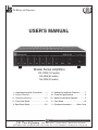
The Mark of the Professional...
USER’S MANUAL
Master Series Amplifiers
DA-120M (120 watts)
DA-60M (60 watts)
DA-30M (30 watts)
I- Unpacking/Inspection Procedures.........1
VI- Settings for Additional Features.............7
II- Product Features...................................1
VII- Technical Specifications.........................8
III- Operating Summary............................2-3
VIII- Master Series Block Diagram................9
IV- Front Panel Detail..................................4
IX - Tech Notes...........................................10
V- Back Panel Detail................................5-6
X- Purchase Information............ Back Cover
NEW TECHNOLOGY
J.W. Davis & Company
OLD RELIABILITY
• 3030 Canton Street • P.O. Box 710219 • Dallas, Texas 75371-0219
Sales 800-527-5705 • Fax 800-388-9106 • Corp 214-651-7341 • Fax 214-939-0328 • [email protected] • www.jwd.com
090705122
The Mark of the Professional...
WARNING: DO NOT CUT OR REMOVE THE GROUND PIN ON THE AC POWER CABLE. DO NOT
USE AC TWO PIN ADAPTER UNLESS IT IS GROUNDED BY AN EXTERNAL GROUND WIRE. CHECK
THE AC WALL RECEPTACLE TO CONFIRM THE PROPER GROUND IS PRESENT.
n
WARNING: TO REDUCE THE RISK OF ELECTRICAL SHOCK, DO NOT REMOVE THE COVER. NO
USER SERVICEABLE PARTS INSIDE. REFER SERVICING TO QUALIFIED SERVICE PERSONNEL.
n
n
WARNING: TO REDUCE THE RISK OF FIRE OR ELECTRICAL SHOCK, DO NOT EXPOSE THIS
UNIT TO RAIN OR MOISTURE.
I - UNPACKING AND INSPECTION PROCEDURES
This unit was carefully checked and packed before leaving the factory. However, the shipping container
and unit should be inspected for indications of improper handling. If the unit has been damaged in transit,
make an immediate claim to the carrier for their inspection. Returning the freight to J.W. Davis & Company
will void your claim with the carrier.
II - PRODUCT FEATURES
The features and benefits listed below make this series of amplifiers unique. They have been designed
with the user’s needs in mind to be products that fit many applications without modifications or additional
equipment.
• 7 Major Application Interfaces
• 6 Switchable Microphone, Line, AUX, or CD/DVD Modules
• 15 Special Signal Inputs
• 7 Signal Outputs
• Power (rated by specific model selected)
• 4~16 Ω, 25 and 70 Volt System Outputs
• 24 VDC Alternate Power Source
• Multiple Music-On-Hold Options
• A switch to activate the 400Hz roll off circuit to protect horn drivers
• Tape out for recording
• Pre-out, Main-In for insertion of signal conditioning equipment such as equalization
• Booster out provides a signal for power amplifiers to expand the system
• FIVE-YEAR WARRANTY
1
NEW TECHNOLOGY
J.W. Davis & Company
OLD RELIABILITY
• 3030 Canton Street • P.O. Box 710219 • Dallas, Texas 75371-0219
Sales 800-527-5705 • Fax 800-388-9106 • Corp 214-651-7341 • Fax 214-939-0328 • [email protected] • www.jwd.com
The Mark of the Professional...
III - OPERATING SUMMARY
The JWD Master Series of monaural amplifiers provide the combination of interface, signal control and
extended mixer capacity required by professional audio system integration. In addition to traditional
commercial sound applications such as paging and background music, the Master Series extends
the scope of capabilities to include integration with telephone communications, audio-visual, security,
sound masking and the analog output of digital devices that previously have been available only in
more complex modular amplifiers. All features are inclusive without requiring additional accessories or
modifications.
The front panel has nine controls (six volume controls plus master, treble and bass) and eleven
LEDs (monitoring the presence of a signal on the six volume controls plus the status of the Telephone, SystemOverRide, Signal Out, Peak and Power circuits). Each of the six volume controls
attenuate one of the six dip switch modules located on the back panel. In addition, each microphone
input has a related recessed Trim Control located on the back panel that can adjust any selected MIC
input’s signal level to the front level control (especially useful when using consumer type equipment
that does not have an adjustable signal control).
The back panel contains six dip switchable modules (example below) that provide the desired signal
inputs by simply setting the indicated dip switches up or down.
Module 1
Switch 1 selects the balance of the incoming signal.
Switch 2 selects either an unbalanced CD/DVD or AUX input. The two RCA jacks electronically combine stereo to a mono signal out. Either RCA jack may be used to input a single mono signal.
Switch 3 connects either the phoenix-type terminal or XLR connector to the input source.
Switch 4 selects either a balanced (Lo - Z) MIC or Line level signal input.
Switch 5 activates the Phantom Power (+24VDC) to use with condenser or electret microphones.
Phantom power is available on either XLR or Terminal inputs.
Switch 6 activates a High Pass Filter on the XLR or Terminal inputs. This filter will roll off frequencies
lower than 150Hz to reduce the “popping” sound of a MIC switch or of consonants in human speech.
Switch 7 (available only on Module 1) activates a Mute Send function. When activated, the MIC
source connected to either the XLR or Terminal input will VOX mute the other five modules.
NOTE: If the Amplifier is frequently moved to different locations, or used as a
portable system, the XLR connectors should be used. The action of plugging
and unplugging the connector maintains a good connection. If the amplifier is
installed in a permanent location, the phoenix-type screw terminals should be
used for a better long-term connection.
2
NEW TECHNOLOGY
J.W. Davis & Company
OLD RELIABILITY
• 3030 Canton Street • P.O. Box 710219 • Dallas, Texas 75371-0219
Sales 800-527-5705 • Fax 800-388-9106 • Corp 214-651-7341 • Fax 214-939-0328 • [email protected] • www.jwd.com
The Mark of the Professional...
Three other dedicated inputs, described below, have independent volume controls located on the
amplifier’s back panel. Neither the Master Volume Control nor the Bass and Treble Controls will affect
these inputs.
(1) Telephone Page input. This shielded, balanced input accepts the signal directly from the
page port out on the telephone system.
(2) Music-On-Hold (“MOH”) input. This input operates through a separate, dedicated internal one-watt
amplifier that permits close control of volume levels.
The music-on-hold RCA-type input accepts the signal
from music, tape messages, company advertisements
or other audio sources. The MOH signal also can be
routed to the main amplifier for distribution to the entire
Music-on-Hold Input
sound system.
(3) SystemOverRide (“SOR”) input . This independent input is not affected by any other amplifier control. Its purpose is Priority signaling, sound masking and other applications that must
not be interrupted by the regular functions of the amplifier. The default SOR setting is for sound
masking applications.
Paging with VOX muting is accomplished either from the MIC input on Module 1 or through the
telephone input. This feature is particularly desirable in installations such as hospitals, airports and
auto dealerships where paging may be required from multiple locations. VOX muting of modules 2
thru 6 is available using MIC 1.
A wide range of background music and audio/visual programming applications are supported
through the RCA-type inputs which can easily be switched to CD/DVD or AUX level; located on each
of the six modules. For applications requiring recording of program material, a special “REC OUT”
jack is available that is located on the back panel.
System expansions requiring greater power are accommodated through the “BOOSTER OUT”
jack which allows the signal from the Master Series amplifier to be connected to the aux input of an
additional amplifier.
An equalizer or other signal modifying devices may be easily inserted using the “PRE OUT” and
“PWR IN” jacks. This feature is especially useful when equalizing a difficult acoustical or reverberant
room.
The Master volume control permits overall attenuation of the six modules. Bass and Treble controls
allow equalization of the voice and music signals.
A 400Hz high pass filter circuit is included to help protect the phenolic diaphragms used in paging
horns from excursion damage caused by low frequencies.
Input-to-output comparator, thermal and overload protection circuits provide warnings of potential
load and input-output issues. If the amplifier senses unstable conditions resulting from overload or signal clipping on the input or output, the peak LED will remain on with no output from the amplifier.
Rack (RAK-M) or wall (WM-M) mounting kits are available as optional accessories.
3
NEW TECHNOLOGY
J.W. Davis & Company
OLD RELIABILITY
• 3030 Canton Street • P.O. Box 710219 • Dallas, Texas 75371-0219
Sales 800-527-5705 • Fax 800-388-9106 • Corp 214-651-7341 • Fax 214-939-0328 • [email protected] • www.jwd.com
The Mark of the Professional...
IV - FRONT PANEL DETAIL
8
1
2
3
4
5
6
12
13
14
15
16
17
1)
2)
3)
4)
5)
6)
7)
8)
9)
10)
11)
Input 1 Signal LED
Input 2 Signal LED
Input 3 Signal LED
Input 4 Signal LED
Input 5 Signal LED
Input 6 Signal LED
System Over Ride Signal LED
Tel/Page Input Signal LED
Amplifier Output Signal LED
Amplifier Peak/Protect LED
Amplifier Power LED
7
18
19
12)
13)
14)
15)
16)
17)
18)
19)
20)
21)
20
10
9
11
21
Input 1 Level Control
Input 2 Level Control
Input 3 Level Control
Input 4 Level Control
Input 5 Level Control
Input 6 Level Control
Bass Control
Treble Control
Master Volume Control
Power Switch (Push-Button)
4
NEW TECHNOLOGY
J.W. Davis & Company
OLD RELIABILITY
• 3030 Canton Street • P.O. Box 710219 • Dallas, Texas 75371-0219
Sales 800-527-5705 • Fax 800-388-9106 • Corp 214-651-7341 • Fax 214-939-0328 • [email protected] • www.jwd.com
The Mark of the Professional...
1)
2)
3)
4)
5)
6)
7)
8)
9)
10)
11)
12)
13)
14)
15)
1
2
13
14
3
4
15
5
6
7
16
17
18
8
9
19
10 11 12 V - BACK PA
20
A/C Fuse: Replace with identical type.
Music-On-Hold Output: transformer balanced, 600 Ω, 1 V (adjustable).
Telephone-Page Input: transformer balanced, 600 Ω, 100 mV. See page 7.
Tel-Page Volume Control: Controls the level of Tel/Page input independent from front volume,
bass and treble controls. See page 7.
Remote Mute (normally open): Used with Module 1 (MIC), allows for a switch to mute Modules
2 thru 6.
VOX Controls: Variable resistor that controls the VOX-Mute sensitivity; one for TEL input and
one for Module 1 (MIC).
Music-On-Hold volume control: Controls level to on-hold circuit of a phone system.
MOH Switch: Allows for the MOH input signal to be shared with AUX input 6. See page 7.
HPF Switch: Activates the 400Hz Low-Cut Filter (high pass filter) to protect horns. Effects
main speaker output only.
SystemOverRide Volume Control: Controls the level of SOR input independent from front
volume, bass and treble controls. See page 7.
SystemOverRide Input: Used for noise masking applications, bypasses front volume and tone
controls. Board level jumper can activate it for priority input, muting Modules 2 thru 6. See page 7
Music-On-Hold Input: Input for MOH source. Can be shared with Aux input 6. See pages 3
and 7.
51/2 ft. Power Cord: 120 VAC/15 Amp.
Chassis Equipment Ground: Used in electronic equipment rack. Do not ground to A/C line.
24 VDC In: The +24 VDC allows the amplifier to be used with emergency backup power supplies. For portable use or where 120 VAC is not available.
5
NEW TECHNOLOGY
J.W. Davis & Company
OLD RELIABILITY
• 3030 Canton Street • P.O. Box 710219 • Dallas, Texas 75371-0219
Sales 800-527-5705 • Fax 800-388-9106 • Corp 214-651-7341 • Fax 214-939-0328 • [email protected] • www.jwd.com
The Mark of the Professional...
ANEL DETAIL
21 22 23 24 25
21
26
22
24
25
16) Speaker Output Terminals: The available screw terminal outputs are 4~16 Ω, 25 V and 70.7 V.
17) REC OUT: Connects signal to a recording device, Unbalanced, 600 Ω, 1 V.
18) BOOSTER OUT: Connects signal to additional power amplifier, Unbalanced, 600 Ω, 1 V.
(19) & (20) PRE OUT/PWR IN: The two RCA jacks offer an opening between the pre amp and the
power section of the amplifier. This allows the insertion of an equalizer or other signal conditioning equipment. Unbalanced. 600 Ω, 1 V.
MODULE SECTIONS 2-6
21) Auxiliary Input: Two channel input will electronically sum stereo signals to mono output of amplifier.
22) Input Trim Control: Recessed variable resistor for adjusting source signal integrity to pre-amp stage.
23) Six-Control Switch Bank: (1) Up=RCA, Down=XLR/TERM; (2) Up=CD/DVD, Down=AUX;
(3) Up=TERM, Down=XLR; (4) Up=MIC, Down=LINE; (5) Up=Phantom Power (+24 VDC),
Down=Off; (6) Up=Off, Down=High Pass Filter On.
24) MIC/LINE BALANCED level input: Removable Phoenix Connector.
25) MIC/LINE BALANCED level input: XLR-Female.
MODULE SECTION 1 ONLY
26) Seven-Control Switch Bank: (1) Up=RCA, Down=XLR/TERM; (2) Up=CD/DVD, Down=AUX;
(3) Up=TERM, Down=XLR; (4) Up=MIC, Down=LINE; (5) Up=Phantom Power (+24 VDC),
Down=Off; (6) Up=Off, Down=High Pass Filter On; (7) Up=MUTE SEND, Down=OFF.
bWARNING: Amplifier must be powered off before changes are made to Switch Banks.
6
NEW TECHNOLOGY
J.W. Davis & Company
OLD RELIABILITY
• 3030 Canton Street • P.O. Box 710219 • Dallas, Texas 75371-0219
Sales 800-527-5705 • Fax 800-388-9106 • Corp 214-651-7341 • Fax 214-939-0328 • [email protected] • www.jwd.com
The Mark of the Professional...
VI - SETTINGS FOR ADDITIONAL FEATURES
TELEPHONE VOX MUTING
The Telephone Page Input (3) will mute inputs one through six. This is a default feature of the M-Series
and cannot be modified. Adjust the sensitivity of the VOX mute using a mini-blade screwdriver to access
the recessed variable control, TEL VOX SENS (6).The transformer-coupled telephone input terminals
will accept either a balanced (3-Wire) or unbalanced (2-Wire) line direct from the telephone page port
out (talk battery without ring). It also accepts a TEL-PAGE output from a digital phone system: (Switch)
G=Sleeve, COM=Ring, HOT=Tip. A 600Ω shielded balanced input transformer is used to aid in the
rejection of RF and EFI.
ACTIVATION OF MICROPHONE 1 VOX MUTING
To activate MIC 1 VOX muting of modules two thru six, simply move switch number 7 up to Mute Send
(26). Adjust the sensitivity of the VOX mute using a mini-blade screwdriver to access the recessed
variable control, MIC 1 VOX SENS (6). This works in conjunction with the TRIM control (22), a recessed
variable input level control. Muting issues may be experienced with certain sources like wireless microphone receivers. For these situations, use the Remote Mute terminal input (5). Simply add an external
switch to mute modules two through six.
WARNING:The following changes should be made only by a qualified technician to avoid the risk of electrical shock and of voiding
the warranty due to static electricity. The unit must be unplugged
from AC or DC power source prior to making changes.
n
ACTIVATION OF THE SystemOverRide INPUT
TO BECOME A PRIORITY INPUT
To activate the SOR to become a priority input,
remove the cover to gain access to the board
level jumper. Facing the back of the amplifier,
the jumper is located on the back left hand side
of the circuit board. It is numbered JP700. (See
Figure 3) To activate, move jumper to short the
ON and middle pin.
Figure 3
NOTE: THE FOLLOWING INPUTS ARE UNIQUE IN THEIR FUNCTIONALITY
The Telephone, System Over Ride, and Music-On-Hold inputs have their own volume controls and bypass
the amplifier’s Master Volume, Bass and Treble controls, which permits the volume levels to be tailored
to the specific use. Typically, telephone paging needs to be set for best intelligibility while adjusting the
front Master volume control for background music.
SystemOverRide is designed for sound masking systems. Call J.W. Davis tech support for this application. Another option for the SOR is for signal notification. Activating the board level jumper will allow
the SOR to mute inputs two through six for use as a signaling device such as a tone generator, or alarm
signal.
The Music-On-Hold input/output does not require tone adjustment due to the limited frequency response
of telephone handsets.
7
NEW TECHNOLOGY
J.W. Davis & Company
OLD RELIABILITY
• 3030 Canton Street • P.O. Box 710219 • Dallas, Texas 75371-0219
Sales 800-527-5705 • Fax 800-388-9106 • Corp 214-651-7341 • Fax 214-939-0328 • [email protected] • www.jwd.com
The Mark of the Professional...
VII - TECHNICAL SPECIFICATIONS
Model Number
DA-30M
DA-60M
DA-120M
Power Rating
30 Watts
60 Watts
120 Watts
Frequency Response50Hz ~ 15kHz (±3dB); TEL: 250Hz ~ 15kHz (±3dB)
S/N Ratio (Tone Controls at Center Detent)
> 60dB
T.H.D.
< 0.8% at 1 kHz, & at Rated Power
MIC
XLR-F
(1 - 6): 150 Ω, 1 mV, or Line XLR-F (1 - 6):
Balanced
10k Ω, 100 mV (MIC TRIM Adjustable)
(1 - 6): 150 Ω, 1 mV, or Line Phoenix (1 - 6):
BalancedMIC Phoenix
10k Ω, 100 mV (MIC TRIM Adjustable)
Inputs
BalancedTelephone/Page: Shielded Transformer, 600 Ω, 100 mV
Aux (1 - 6): 2-Channel Audio Electronically Summed to Mono
Output, 47k Ω, 100 mV, or DVD/CD (1-6):
Unbalanced
2-Channel Audio Electronically Summed to Mono Output,
47k Ω, 360 mV
Unbalanced
MOH: 47k Ω, 100 mV
Unbalanced
SOR: 47k Ω, 100 mV
Unbalanced
Power-In: 47k Ω, 1 V
Microphone Phantom Power (Switchable on Modules 1 thru 6): +24 VDC
4 ~ 16 Ω, & 25 V, & 70.7 V (Any Combination Not To Exceed Rated Power)
MOH: Transformer-Isolated 600 Ω, 0 ~ 1 V (Adjustable)
Outputs Rec (Tape) Out: 600 Ω, 1 V, Pre Tone Controls
Booster Out: 600 Ω, 1 V, Pre Tone Controls
Pre-Out: 600 Ω, 1 V, Post Tone Controls
Telephone VOX Mute: -40dB, VOX Sensitivity Adjustable
MIC 1 VOX: -37dB (Via Switch # 7 “Mute Send”),
VOX Sensitivity Adjustable
VOX (Voice) Mute Circuits
SOR VOX: -40dB (Via Circuit Board Jumper # 700)
Remote Mute Terminal (Use w/ MIC 1), -37dB
Tone ControlsBass: ± 10dB at 100Hz Treble: ± 10dB at 10kHz
High Pass Filter HPF (Switchable)
400Hz, -6dB/Octave (4 ~ 16 Ω, 25 V, & 70.7 V Outputs Only)
Inputs 1 thru 6, Tel, SOR, Signal Output,
Indicators
Peak Signal Output (Steady On = Amp Protect), & Power LEDs
120 VAC
Power Source
+24 VDC
Power Consumption
100W
200W
300W
Built-In Signal Clip Comparator on Input to Output to Speaker Load,
Protection
Thermal, Overload and Short Circuit Protection
Dimensions 16.5″ W x 13.5″ D x 4.3″ H (2 RU w/o feet)
Weight
16 Lbs.
19 Lbs.
27 Lbs.
Shipping Weight
21 Lbs.
24 Lbs.
33 Lbs.
Available Accessories
RAK-M: 19″ Rack Mount Kit, WM-M: Surface Wall Mount Kit
Specifications subject to change without notice.
8
NEW TECHNOLOGY
J.W. Davis & Company
OLD RELIABILITY
• 3030 Canton Street • P.O. Box 710219 • Dallas, Texas 75371-0219
Sales 800-527-5705 • Fax 800-388-9106 • Corp 214-651-7341 • Fax 214-939-0328 • [email protected] • www.jwd.com
The Mark of the Professional...
VIII - MASTER SERIES BLOCK DIAGRAM
NOTE: A detailed schematic may be obtained by contacting our Customer Service Department.
9
NEW TECHNOLOGY
J.W. Davis & Company
OLD RELIABILITY
• 3030 Canton Street • P.O. Box 710219 • Dallas, Texas 75371-0219
Sales 800-527-5705 • Fax 800-388-9106 • Corp 214-651-7341 • Fax 214-939-0328 • [email protected] • www.jwd.com
The Mark of the Professional...
IX - TECH NOTES
HIGH IMPEDANCE OF 25 AND 70.7 V SYSTEMS
The high impedance or constant voltage method of impedance matching uses a high impedance amplifier output which is
transformed down to 8 Ohms by an impedance matching transformer at each individual speaker. The big advantages of
this approach as compared to low impedance are:
(1) Reduced line losses and ability to use smaller wire gauges. This is due to the higher voltage and reduced current
in the speaker lines.
(2) Much simpler impedance matching procedures and connections.
Constant voltage is a misnomer in that the amplifier does not always produce 70 V. Rather, the amplifier output impedance is set at such a level that, irrespective of its rated power, it will produce 70.7 Volts output at full power. Thus a 10
Watt amplifier optimum load would have an impedance of 500 Ohms (P = 70.7²/500), a 40-Watt amp would be 126 Ohms
and 120-Watt amp, 42 Ohms.
Multiple transformer taps allow the impedance at each speaker to be adjusted individually to give a total matched load.
Because of the high impedance arrangement, the system is easier to impedance match and is also inherently less susceptible to problems caused by mismatching.
The transformer taps are marked in W=watts instead of Ohms (usually 4, 2, 1, 1/2). Again, it should be born in mind
that these levels of power output are only achieved when the transformer is working at 70.7 Volts. The transformers are
connected in parallel. A good match is obtained by ensuring that the total of all tap settings fits into the range of 40-80%
of rated amplifier output. 80% is chosen to allow for transformer insertion loss. Also, It is good practice not to drive the
amplifier to 100% of its capacity.
Examples are shown below. For simplicity, it is assumed that all tap settings are the same at each speaker. For a 120Watt amplifier, the range 40-80% is equivalent to 48-96 Watts. Therefore:
18 speakers x 4 Watt taps each = 72W............................. Good match
12 speakers x 1 Watt taps each = 12W............................. Poor match
60 speakers x 1 Watt taps each = 60W............................. Good match
60 speakers x 4 Watt taps each = 240W........................... Very poor match – overload
90 speakers x 1 Watt taps each = 90W............................. Good match
POWER LOSS IN LONG LINES
For long lines, the power loss in watts becomes a significant factor. The power supplied by the amplifier is effectively
reduced by the line loss. For a 0.5 dB loss in sound pressure the total wire resistance must be limited to 6% of speaker
impedance. The table below shows the calculated two-wire cable lengths permissible for a number of wire sizes in feet.
For a 1 dB loss, the lengths may be doubled. For 2 dB loss, multiply by 4.4.
AWG
Size
Low-Impedance High Impedance Systems
Resistance
100W/70.7 V
(ohms/1000
4 ohms 8 ohms 16 ohms 12.5W/25 V
feet)
(50 ohms)
50W/70.7 V
6.25W/25 V
(100 ohms)
25W/70.7 V
3.5W/25 V
(200 ohms)
14
2.5
48
96
190
600
1,200
2,400
16
4.20
30
60
90
370
740
1,500
18
6.39
19
38
76
230
460
920
20
10.1
12
24
48
150
300
600
22
16.2
7
14
28
93
190
380
10
NEW TECHNOLOGY
J.W. Davis & Company
OLD RELIABILITY
• 3030 Canton Street • P.O. Box 710219 • Dallas, Texas 75371-0219
Sales 800-527-5705 • Fax 800-388-9106 • Corp 214-651-7341 • Fax 214-939-0328 • [email protected] • www.jwd.com
JWD Master Series Amplifiers
Thank you for selecting a J. W. Davis Master Series Amplifier. Since 1933, it has been our goal to
produce a complete line of quality products and to offer a FIVE YEAR WARRANTY on most J.W.
Davis items. You will not see our products advertised in a discount catalog or other consumer
venues since we limit our sales to qualified professionals. Having bought through a professional,
you may use J.W. Davis & Company products with confidence and pride.
For your next installation please consider the other fine J.W. Davis products such as power
amplifiers, pre-Amplifiers, mixers, microphones, speakers, speaker systems, horns, lecterns,
baffles, transformers, volume controls, and accessories.
Also, be sure to check our web site (www.jwd.com) for additional manufacturers’ products that
we distribute.
PURCHASE INFORMATION FOR YOUR RECORDS:
SERIAL NUMBER
PURCHASE DATE
INSTALLATION DATE
INSTALLED BY
PURCHASED FROM
ADDRESS
CITY & STATE
TELEPHONE NUMBER
NAME