1
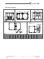
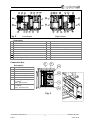
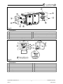
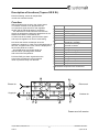
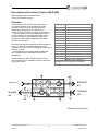
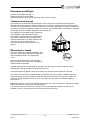
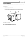
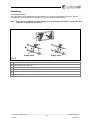
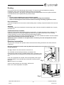
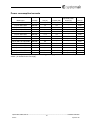
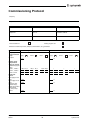
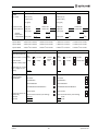
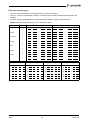
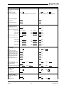
Topvex SR07, SR09, SR11 E Compact Air Handling Unit GB GB Installation instruction Corrigo ver. no. 3.0-1-03 Dimensions & weight Optional: Exhaust top connection Fig.1 Min. space for rotor change: A-150mm Model spec. Topvex SR07 E Topvex SR09 E Topvex SR11 E A 1000 1120 1230 B 600 600 800 C 300 400 400 D 125 108 135 E 150 104 165 F 200 260 215 G 795 915 1025 K 337 434 487 L 195 195 195 M 145 145 145 Weight kg 320 365 435 _____________________________________________________________________________________________________ Topvex SR07, SR09, SR11 E Installation instruction 2 205870 Systemair AB Fig. 2 Left version Right version Description 1. Supply air 10. Rotor motor 2. Extract air 11. Filter, Extract air 3. Exhaust air 12. Filter, supply air 4. Outside air 13. Pressure transmitter supply air fan 5. Pressure sensor supply air filter 14. Electrical Heater/Water coil 6. Fan, extract air 15. Electrical Connection box (see fig.3) 7. Fan supply air 16. Pressure sensor extract air filter 8. Control Heat exchanger 17. Pressure transmitter extract air fan 9. Heat exchanger, Rotor Connection box Description 20. Fuse heater 21. Fuse fans 22. 24 V Transformer 23. Control unit Corrigo 24. Contactor 25. ADO – terminal block tool 26. Overheating protection , EL- heating battery, Manual reset. 27. Overheating protection EL- heating battery, Automatic reset. Fig. 3 _____________________________________________________________________________________________________ Topvex SR07, SR09, SR11 E Installation instruction 3 205870 Systemair AB Fig. 4 Description 1. Supply air 6. VAV pressure transmitter extract air (accessories) 2. Extract air 7. Damper and motor exhaust air (accessories) 3. Exhaust air 8. Damper and motor outside air (accessories) 4. Outside air 9. Sensor supply air 5. VAV pressure transmitter supply air (accessories) Fig. 5 Description 1. Alarm button 7. 2. Alarm LED 7a. Yellow cable Connection block 3. Write enable LED 7b. Orange cable 4. OK button 7c. Red cable 5. Clearing button 7d. Brown cable 6. Mounting holes 7e. Black cable _____________________________________________________________________________________________________ Topvex SR07, SR09, SR11 E Installation instruction 4 205870 Systemair AB Introduction Installation, operation and maintenance manual concerns air handling unit type Topvex SR, manufactured by Systemair AB. It consists of basic information and recommendations concerning the design, installation, start-up and operation, to ensure a proper fail-free operation of the unit. The key to proper and safe operating of the unit is to read this manual thoroughly, use the unit according to given guidelines and follow all safety requirements. Table of contents Dimensions & weight ................................................................................................................ 2 Introduction............................................................................................................................... 5 Table of contents ...................................................................................................................... 5 Declaration of Conformity ......................................................................................................... 6 Electrical connection ................................................................................................................ 7 Description of functions (Topvex SR E EL) .............................................................................. 8 Description of functions (Topvex SR E HW) ............................................................................ 9 Dimension and Weight ........................................................................................................... 10 Transport and storage ............................................................................................................ 10 Where/how to Install ............................................................................................................... 10 Separating the appliance........................................................................................................ 11 Plumbing ................................................................................................................................ 12 Connecting to water ........................................................................................................... 12 Ducting ................................................................................................................................... 13 Duct connections ................................................................................................................ 13 Attention ............................................................................................................................. 13 Condensation/heat insulation. ............................................................................................ 13 Electrical connection .............................................................................................................. 13 Power consumption/currents .............................................................................................. 14 External connections .............................................................................................................. 15 Timer (Extended operation) ................................................................................................ 15 Push button (Extended operation) ...................................................................................... 15 Damper, outdoor/exhaust air .............................................................................................. 15 Cooling battery ................................................................................................................... 15 HW valve/actuator .............................................................................................................. 15 Fire alarm ........................................................................................................................... 15 Room sensor ...................................................................................................................... 15 E-Tool (commissioning software) ....................................................................................... 15 Communication to BMS (Building Management System) .................................................. 15 Components ........................................................................................................................... 16 Heat exchanger .................................................................................................................. 16 Heater battery ..................................................................................................................... 16 Electrical heater .................................................................................................................. 16 Hot water heater ................................................................................................................. 16 Control panel ...................................................................................................................... 16 Commissioning ....................................................................................................................... 17 Before starting the system .................................................................................................. 17 Commissioning protocoll.........................................................................................................18 _____________________________________________________________________________________________________ Topvex SR07, SR09, SR11 E Installation instruction 5 205870 Systemair AB Declaration of Conformity Manufacturer Systemair AB Industrivägen 3 SE-73930 Skinnskatteberg SWEDEN Office: +46 222 440 00 Fax: +46 222 440 99 www.systemair.com hereby confirms that the following products: Air handling units Topvex SR 07 E EL Topvex SR 09 E EL Topvex SR 11 E EL Topvex SR 07 E HWL/HWH Topvex SR 09 E HWL/HWH Topvex SR 11 E HWL/HWH (The declaration applies only to product in the condition it was delivered in and installed in the facility in accordance with the included installation instructions. The insurance does not cover components that are added or actions carried out subsequently on the product) Comply with all applicable requirements in the following directives Machinery Directive 2006/42/EC Low Voltage Directive 2006/95/EC EMC Directive 2004/108/EC The following harmonized standards are applied in applicable parts: Safety of machinery – Basic concepts, general principles for design – Part 1: Basic terminology, methodology EN ISO 12100-2 Safety of machinery – Basic concepts, general principles for design – Part 2: Technical principles EN 14121-1:2007 Safety of machinery – Risk assessment – Part 1: Principles EN 13857 Safety of machinery – Safety distances to prevent hazard zones being reached by upper or lower limbs EN 60 335-1 Electric domestic products and similar – safety-general requirements EN 60 335-2-40 Safety of household and similar electrical appliances - Part 2-40: Particular requirements for electrical heat pumps, air-conditioners and dehumidifiers. EN 50 106 Safety of household and similar appliances – Particular rules for routine tests referring to appliances under the scope of EN 60 335-1 and EN 60967 EN 60 529 Degrees of protection provided by enclosures (IP code) EN 61000-6-2 Electromagnetic compability (EMC) – Part 6-2: Generic standards – Immunity for industrial environments EN 61000-6-3 Electromagnetic compability (EMC) – Part 6-3: Generic standards – Emission standards for residential, commercial and light-industrial environment EN ISO 12100-1 The complete technical documentation is available. Skinnskattberg 11-02-2011 Mats Sándor Technical Director _____________________________________________________________________________________________________ Topvex SR07, SR09, SR11 E Installation instruction 6 205870 Systemair AB Electrical connection Terminal block 1 2 3 4 5-12 13 14 15-26 L1 L2 L3 N G G0 Remark Description See the rating plate for correct supply voltage. Phase (supply voltage) Earth neutral (supply voltage) For internal use 24V AC, 0,5A Neutral For internal use Water valve actuator, supply voltage (HW units only) Water valve actuator (HW units only) PT 1000 Temp. sensor, Outdoor air (when needed, disconnect the standard sensor and replace it with the wall mounted temperature sensor). AI ref is terminal block 62. 27 AI 28 29 -30 UAI2 31 AI 32 33 34 35 36 AI ref DO G0 G DO 37 G0 Neutral 38 G 24V AC 39 40 41-42 43 44 45 46 *47 DO DO AO AO ref N L1 DI *48 *49 50 51 52 53 54 55 56 57 58 *59 60 61 62 63 DI DI DI ref Net + Net DO ref DO DO AI3 AO UAI3 DI G AI AI ref AI *64 DI 65-67 Free to use For internal use PT 1000 Reference 24V AC, 0,5A Neutral 24V AC 24V AC, 0,5A 24V AC, 0,5A 24V AC, 0,5A For internal use 0-10V DC Reference Neutral 230V AC or Temp. sensor, Supply air Damper, exhaust air By spring- loaded Damper, exhaust air damper connect 33/35 Damper, exhaust air By spring-loaded Damper, outdoor air damper connect 36/38 Damper, outdoor air Water valve actuator cooling (EL units only) Damper, outdoor air Water valve actuator cooling (EL units only) Water pump, control voltage (contactor). Cooling Sum alarm, A- and B-alarm Control signal water valve actuator heating/cooling Only for EL models Water pump, supply voltage. HW Heating Water pump, supply voltage. HW Heating Fire alarm External stop Extended operation, Normal Reference LON LON Reference 24V AC, 0,5A 24V AC, 0,5A 0-10V DC 24V AC 0-10V DC Reference 0-10V DC or DX cooling, step2 DX cooling, step1 Sensor extract air Control signal water cooling Free to use External alarm Pressure transmitter, supply voltage Pressure transmitter, control signal. Supply air Pressure transmitter Pressure transmitter, control signal. Extract air Run-indication/alarm circulation pump Cooling Free to use * These inputs may only be wired to voltage free contacts. _____________________________________________________________________________________________________ Topvex SR07, SR09, SR11 E Installation instruction 7 205870 Systemair AB Description of functions (Topvex SR E EL) Electrical heating, extract air temperature control with cascade function. Function Start and stop times are set in the Control panel. To maintain constant room temperature the UC receives a signal from ETS and regulates the HE and the electrical heater in sequence. The SS sensor is used to limit the max and min supply air temperature. Maximum temperature in the electrical re-heater is controlled by ET. OT disconnects the heater, gives an alarm signal and stops the appliance in case of overheating. DO closes the outdoor air damper when the appliance is stopped. In case of an unintended stop on the rotor, a signal is sent to RC, which is displayed on the Control panel as an alarm. Also displayed in the Control panel are date and time, operating status, desired and actual room temperature. FGS and FGE give alarm signals when the actual value exceeds the pre-set desired value for pressure drop over the filter. Designation Name EF SF SS OS ETS Extract air fan Supply air fan Sensor, supply air Sensor, outdoor air Sensor, extract air Sensor, max temperature in the electric re-heater Sensor, overheating in the electrical re-heater Filter guard extract air Filter guard supply air Regulator Corrigo E28 Control box for rotor Driving motor, rotor wheel Energy exchanger, rotor wheel Damper motor, outdoor air Damper motor, exhaust air ET OT FGE FGS UC RC RM HE DO DEH NB! Dashed components are accessories Extract air Exhaust air Supplyair Outdoor air Drawn as a left version _____________________________________________________________________________________________________ Topvex SR07, SR09, SR11 E Installation instruction 8 205870 Systemair AB Description of functions (Topvex SR E HW) Water heating, extract air temperature control with cascade function. Function Start and stop times are set in the Control panel. To maintain constant room temperature the UC receives a signal from ETS and regulates the HE and WVA in sequence. The SS sensor is used to limit the max and min supply air temperature. If there is a risk of frost in the water heater WVA opens completely. If the temperature drops further, an alarm is set off and the appliance stops. FPS maintains constant water temperature even when the fans have stopped. DO closes the outdoor air damper when the appliance stops. In case of an unintended stop on the rotor, a signal is sent to RC, which is displayed on the Control panel as an alarm. Also displayed in the Control panel are date and time, operating status, desired and actual room temperature. FGS and FGE give alarm signals when the actual value exceeds the pre-set desired value for pressure drop over the filter. Extract air Designation Name EF SF SS OS ETS FPS Extract air fan Supply air fan Sensor, supply air Sensor, outdoor air Sensor, extract air Frost protection sensor Filter guard extract air Filter guard supply air Regulator Corrigo E28 Control box for rotor Driving motor, rotor wheel Energy exchanger, rotor wheel Actuator, hot water Damper motor, outdoor air Damper motor, exhaust air FGE FGS UC RC RM HE WVA DO DEH NB! Dashed components are accessories Exhaust air Outdoor air Supply air Drawn as a left version _____________________________________________________________________________________________________ Topvex SR07, SR09, SR11 E Installation instruction 9 205870 Systemair AB Dimension and Weight Dimension and weight See fig. 1. Handle and hinges are removable. Inspection doors can open without handle by using a 16mm cap key. Transport and storage The Topvex should be stored and transported in such a way that it is protected against physical damage that can harm panels, handles, display etc. It should be covered so that dust, rain and snow cannot enter and damage the unit and its components. The unit is delivered in one piece containing all necessary components, wrapped in plastic on a pallet for easy transportation. If separation is required, please refer to section headed "Separation of the appliance". The appliance may be lifted using a forklift truck or be elevated using metal tubes inserted through the holes in the feet and suspended by soft cables. If possible secure the ends of the metal bars and cables. To avoid collapse of the unit’s feet, do not try to slide the unit into place after it has been put down on the ground. Where/how to Install The unit is meant for horizontal installation. The electronic components should not be exposed to lower temperature than 0°C or higher than +50°C. When mounting; make sure to leave enough space to access the service doors. See fig.1 for measurement requirements. General maintenance includes replacing the filters and removing fan motors inside the unit for cleaning and cleaning the heat exchanger inside the unit. Avoid placing the unit against a wall, as low frequency noise can cause vibrations in the wall. The outdoor air intake of the building should if possible be put in the northern or eastern side of the building and away from other exhaust outlets like kitchen fan outcasts or laundry room outlets. The extract air should ideally be led out via a roof cowl away from any outdoor air intakes, windows, balconies etc. Note! If the handles are used, the required safety for the unit is only reached if the handles are locked and the keys kept in a secure place during operation. The unit must be duct connected or in some other way provided with protection so that it is not possible to come in contact with the fans through the duct connections. _____________________________________________________________________________________________________ Topvex SR07, SR09, SR11 E Installation instruction 10 205870 Systemair AB Separating the appliance On delivery the two halves of the Topvex appliance are mounted together. If necessary they can be separated for easy transport to the site of installation. How to split the unit: A. B. C. D. E. Loosen the cable connectors in the wall The two halves of the appliance are joined using 4 M10 screws, one in each corner Control section Heat recovery section It’s possible to dismount the gables by removing 6 MRX M6 screws with TH2 bits tool Reassemble in the reverse order. The illustration shows a left-handed version of the unit. Important! When reassembling the pieces make sure they are connected correctly - see cable markings on the side of the cables. _____________________________________________________________________________________________________ Topvex SR07, SR09, SR11 E Installation instruction 11 205870 Systemair AB Plumbing Connecting to water The water battery is equipped with two pipes (see fig. 6). These have hexagonal connectors, internal threaded tube. Cover plates around the pipes are fixed to the unit (reinforcement). Note! Take care not to damage the water battery when connecting water pipes to connectors. Use a spanner to tighten the connection. 2-way valve 3-way valve Fig. 6 Description A. B. C. D. E. F. Frost protection sensor (standard) Internal dimension 15R (1/2’’) Pump, secondary circuit Non return valve Valve actuator + water valve (accessories) Pump, primary circuit ____________________________________________________________________________________________________ Topvex SR07, SR09, SR11 E Installation instruction 12 205870 Systemair AB Ducting Air to and from the unit is led through a duct system. To ensure long life and satisfactory cleaning possibilities, ducts made of galvanized steel are highly recommended. To obtain high efficiency, low energy consumption and the required airflow, the duct system should be commissioned for low air speeds and low pressure drops. NOTE! Do not connect tumble dryers to the ventilation system Duct connections/duct ends should be covered during storage and installation Grilles for discharge/roof units must be installed according to building regulations in force. Duct connections To ensure air tightness the connections needs sealing strips or sealing compound between the ducts and the unit. Attention To avoid fan noise being transferred via the ducting system, silencers should be installed both on supply and extract air. Condensation/heat insulation. All the air ducts must be well insulated against condensation. To obtain the heat recovery efficiency it is especially important to insulate the Supply and Extract air ducts against heat losses. Use insulating covering (minimum 100 mm mineral wool) with plastic diffusion barrier. In areas with extremely low outdoor temperatures during the winter, additional insulation must be installed. Total insulation thickness must be at least 150 mm. NOTE! If the unit is installed in a cold place make sure that all joints are well taped and covered with insulation. Electrical connection The unit must not be put into operation before all the electrical safety precautions have been read and understood. Electrical connections must be made by authorized installer and in accordance with current wiring regulations. See fig. 2 where to find the electrical connection box. The TOPVEX unit should be permanently connected to the mains electric supply through a lockable safety switch, as shown in fig. 7. The safety switch is not mounted from the factory but delivered with the unit. If the unit is equipped with a heater, which has separate power supply (see table below). The unit shall bee provided with a working switch, see fig. 8. Fig. 7 N.B this switch is not included. Switch for disconnection from the supply, shall have at least 3 mm contact separation in all poles. Fig. 8 ____________________________________________________________________________________________________ Topvex SR07, SR09, SR11 E Installation instruction 13 205870 Systemair AB Power consumption/currents Model spec. Voltage Unit (A) Heater (kW) Heater with separate power supply (A) Topvex SR07 E HWL/HWH 400V3N~ 3,0 - - 3x10 Topvex SR07 E EL 400V3N~ 7,3 3,0 - 3x10 Topvex SR07 E EL 400V3N~ 3,0 *12,0 *17,5 3x25 Topvex SR07 E EL 400V3N~ 3,0 *12,0 *30 (230V 3~) 3x40 Topvex SR09 E HWL/HWH 400V3N~ 5,4 - - 3x10 Topvex SR09 E EL 400V3N~ 11,9 4,5 - 3x16 Topvex SR09 E EL 400V3N~ 5,4 *15,0 *22 3x32 Topvex SR09 E EL 400V3N~ 5,4 *15,0 *38 (230V 3~) 3x50 Topvex SR11 E HWL/HWH 400V3N~ 8,8 - - 3x13 Topvex SR11 E EL 400V3N~ 17,5 6,0 - 3x13 Topvex SR11 E EL 400V3N~ 8,8 *12,0 *17.5 3x20 Topvex SR11 E EL 400V3N~ 8,8 *24,0 *35 3x50 Topvex SR11 E EL 400V3N~ 8,8 *12,0 *30 (230V 3~) 3x63 Fuse (A) Topvex SR11 E EL 400V3N~ 8,8 *24,0 *60 (230V 3~) 3x80 *Electic heater (above 6 KW) has separate incoming power supply. For 230V3~ a transformer (230V3~ to 400V3~) is needed for the unit supply. ____________________________________________________________________________________________________ Topvex SR07, SR09, SR11 E Installation instruction 14 205870 Systemair AB External connections See page 6 and the attached wiring diagram, how to connect the electrical cables. Timer (Extended operation) When the unit is running on reduced speed or is in shutdown mode it can be forced up one step as long as the timer switch is closed. Set the Extended operating in the control panel to 0 minutes. Push button (Extended operation) When the unit is running on reduced speed or is in shutdown mode it can be forced up one step by using a Push button (impulse). Set the Extended operating in the control panel to the required time, in minutes. Damper, outdoor/exhaust air The outdoor / exhaust air damper (Supply voltage 24V AC, Spring return) is used to avoid cold air to enter the building when the unit is stopped e.g. during the night. See fig. 4 where to assemble the dampers and page 6 how to connect the electrical wiring. The damper is also preventing the hot water battery (HW models) from freezing by closing when the returning water in the battery is below a set temperature, +7C. Cooling battery A water valve actuator (Supply voltage 24V AC, Control signal 0-10 V) can be connected to the unit and be operated in sequence to the heater battery. A DX-cooler can be connected to the unit. See page 6 to see which terminal blocks to use. HW valve/actuator A water valve actuator (Supply voltage 24V AC, Control signal 0-10 V) can be connected to the unit to control a 2 or 3-way water valve. See page 6 to see which terminal blocks to use. Fire alarm Connects to an external fire central. Choose if the unit should stop or run on normal fan speed when the alarm is activated. The Alarm activates thru a digital input DI that can be set to normal open or normal closed. Room sensor A room sensor can be connected to the unit. UAI3 on terminal block 58 (see page 6) can be configured for this purpose. E-Tool (commissioning software) Wirings are to be connected directly to the Corrigo E28 controller (see fig.3 pos.23) on terminal 50-52 (B, A, N). N.B. For more detailed information see the instruction attached to the E-Tool software program. Communication to BMS (Building Management System) Exoline and Modbus via a built in RS-485 contact is included as standard. LON and Exoline via TCP/IP are available as accessories. Communication wirings are to be connected directly to the Corrigo E28 controller (see fig.3 pos.23) on terminal 50-53 (B, A, N, E), 57-59 (Net+, Net-, Egnd) or the TCP/IP terminal. N.B. For more detailed information see the attached Corrigo E – User Manual. ____________________________________________________________________________________________________ Topvex SR07, SR09, SR11 E Installation instruction 15 205870 Systemair AB Components Heat exchanger Topvex has a high efficient rotating heat exchanger. Required supply air temperature is therefore normally maintained without adding additional heat via the built in re-heater battery (water or electric). The operation of the heat exchanger is automatic and depends on the set temperature. The heat exchanger is not removable and has to be cleaned inside the unit. Heater battery Topvex has a built in heater battery (water or electric). The operation of the heating battery is automatic and dependent on the set temperature. Electrical heater The heating rods are located in the heater beside the supply air fan (see fig. 2 and 3) and the material is stainless steel. The electric heating coil has both automatic and manual overheating protection. The power demand of the electric heating coil is controlled by a triac power regulator (Pulser) according to the desired supply/extract or room air temperature that is set in the control panel. Hot water heater The hot water coil is located beside the supply air fan (see fig. 2). The coil is mounted with the connection pipes projecting from the side of the unit and is therefore easy to connect (see fig. 1). The material is copper piping with a frame of galvanized sheet steel and aluminum fins. The coil has a venting nipple and an immersion sensor as frost guard. If there is a risk of freezing in the hot water coil, the control valve is forced open to prevent freezing. If there is still a risk of freezing, the unit is stopped and the outdoor sir dampers (accessory) are closed. Control panel The SCP control panel is delivered with a 10m cable that is pre-connected to the panel and with a fast coupling contact, pre-connected to the Topvex unit. The contact is connected to the Corrigo controller in the electrical connection box (fig. 3). The cable can be unscrewed in the back of the control panel (fig 5). General information is shown in (fig 5). How to operate The menus in the Corrigo E-controller are organized in a horizontal tree structure. The UP/DOWN-buttons are used to move between menus at the present menu level. The RIGHT/LEFT buttons are used to move between menu levels. When changing parameters the UP/DOWN buttons are used to increase/ ecrease the value of the parameter and the RIGHT/LEFT buttons to move between digits within the parameter. The OK button is used to confirm the choice of a parameter setting. The C button is used to abort an initiated parameter change and restore the original value. The ALARM button is used to access the alarm list. Changing parameters In some menus there are parameters that can be set. This will be indicated by the LED flashing. To change a parameter, first press the OK button, the LED changes to a steady light. A cursor will appear at the first settable value. If you wish to change the value, do so by pressing the UP/DOWN buttons. In numbers containing several digits you can move between the digits using the LEFT/RIGHT-buttons. When the desired value is displayed presses OK. If there are further settable values displayed the cursor will automatically move to the next one. To pass a value without changing it, press RIGHT. To abort a change and return to the initial setting, press and hold the C-button until the cursor disappears. ____________________________________________________________________________________________________ Topvex SR07, SR09, SR11 E Installation instruction 16 205870 Systemair AB Navigating the menus The start display, the display normally shown, is at the root of the menu tree. Pressing DOWN ▼ will move you through the menu choices at this, the lowest level. UP ▲ will move you back through the choices. To enter a higher menu level, use UP or DOWN to place the display marker opposite the menu you wish to access and press RIGHT ►. If you have sufficient log on privileges the display will change to the menu you have chosen. At each level there may be several new menus through which you may move using the UP/DOWN buttons. Sometimes there are further submenus linked to a menu or menu item. This is indicated by an arrow symbol at the right-hand edge of the display. To choose one, use RIGHT ► again. To back down to a lower menu level, use LEFT ◄. Commissioning When the installation is finished, check that: - the unit is installed in accordance with these instructions. - sound attenuators are installed and that the duct system is correctly connected to the unit. - outdoor air intake is positioned with sufficient distance to pollution sources (kitchen ventilator exhaust, central vacuum system exhaust or similar). Before starting the system Control that all external equipment are connected. See operating and maintenance instructions, "Operation". Switch on fuse in the unit. Switch on the supply voltage. Set present time and date, set the control temperature and program the week schedule. Do the necessary settings for extra functions if any. Check that: - there is no unusual noise from the unit. - control panel and lamp signals are in function. ____________________________________________________________________________________________________ Topvex SR07, SR09, SR11 E Installation instruction 17 205870 Systemair AB &RPPLVVLRQLQJ 3URWRFRO &RPSDQ\ 5HVSRQVLEOH &XVWRPHU 'DWH ,QVWDOODWLRQ 2EMHFW8QLW ,WHP QR ,QVWDOODWLRQ DGGUHVV 0RGHOVL]H 6HULDO QXPEHU 7LPH DQG GDWH VHW :HHNO\ SURJUDP VHW ([WHUQDO FRQQHFWLRQV VHQVRUV GDPSHUV H[WHUQDO DODUP HWF SHUIRUPHG )XQFWLRQ 'HIDXOW VHWWLQJ 7HPS & &RQWURO IXQFWLRQ WHPS 6XSSO\ 6HW SRLQW 6HW YDOXH ([WUDFW 5RRP & 6XSSO\ ([WUDFW 5RRP & 2XWGRRU WHPS FRPSHQVDWHG VXSSO\ DLU FRQWURO 2XWGRRUVXSSO\ DLU WHPS 3RLQW DQG 3RLQW DQG 3RLQW DQG ,I &DVFDGH FRQWURO /RZ VXSSO\ DLU VHW SRLQW & +LJK VXSSO\ DLU VHW SRLQW & 6ZLWFKLQJ SRLQW RXWGRRU WHPS VXSSO\ ZLWK RXWGRRU FRPSH[WUDFW DLU URRP WHPS & FRQWURO & & & Topvex SR07, SR09, SR11 E 5870 Installation instruction 8 SyVWHPDLU $% )XQFWLRQ 'HIDXOW VHWWLQJ 6HW YDOXH $LUÀRZ PK $LUÀRZ PK 3UHVVXUH 3D 3UHVVXUH 3D &2 SSP &2 SSP $LUÀRZ )DQ FRQWURO 6HW SRLQW QRUPDO 6XSSO\ IDQ ([WUDFW IDQ 6XSSO\ IDQ ([WUDFW IDQ 6HW SRLQW UHGXFHG 6XSSO\ IDQ ([WUDFW IDQ 6XSSO\ IDQ ([WUDFW IDQ /RZHU SRLQW 2XWGRRU WHPSHUDWXUH FRPSHQVDWLRQ 8SSHU SRLQW & PK /RZHU SRLQW & PK & PK 8SSHU SRLQW & PK 7RSYH[ 65 PK RU 3D PK RU 3D PK RU 3D PK RU 3D 7RSYH[ 65 PK RU 3D PK RU 3D PK RU 3D PK RU 3D 7RSYH[ 65 PK RU 3D PK RU 3D PK RU 3D PK RU 3D )XQFWLRQ 'HIDXOW VHWWLQJ 6HW YDOXH &RROLQJ ORJRQ WR V\VWHP OHYHO UHTXLUHG 1RW &RQWURO IXQFWLRQ FRROLQJ DFWLYH 2QRII IXQFWLRQ ± 9 VWHS 1XPEHU RI ELQDU\ VWHSV 2Q2II %LQDU\ VWHS VWHS 1RW DFWLYH ± 9 2Q2II VWHS VWHS %LQDU\ VWHS /RZHULQJ RI PLQ FRQWURO WHPS VXSSO\ DLU '; FRROLQJ & +XPLGLW\ &RQWURO IXQFWLRQ KXPLGL¿FDWLRQ 1RW DFWLYH 1RW DFWLYH +XPLGL¿FDWLRQ +XPLGL¿FDWLRQ 'HKXPLGL¿FDWLRQ 'HKXPLGL¿FDWLRQ +XPLGL¿FDWLRQ'HKXPLGL¿FDWLRQ +XPLGL¿FDWLRQ'HKXPLGL¿FDWLRQ 5RRP VHQVRU 6HQVRUV 9 '& IRU 5+ 5RRP DQG 'XFW VHQVRU PD[ OLPLWLQJ 5RRP VHQVRU 5RRP DQG 'XFW VHQVRU PD[ OLPLWLQJ 6WDUW OLPLW 5+ 5+ 6WRS OLPLW 5+ 5+ Topvex SR07, SR09, SR11 E 5870 Installation instruction 9 SyVWHPDLU $% 6HWWLQJ WKH ZHHNO\ SURJUDP 7LPHV IRU QRUPDO DQG UHGXFHG IDQ VSHHG LV IDFWRU\ VHW DV VKRZQ EHORZ 3HULRG WR 0RQGD\ WR )ULGD\ QRUPDO IDQ VSHHG WR 6DWXUGD\6XQGD\ DQG KROLGD\V 3HULRG WR 0RQGD\ WR 6XQGD\ DQG SXEOLF KROLGD\V WR RII SHULRG 2%6 1RUPDO IDQ VSHHG KDV SULRULW\ RYHU D UHGXFHG IDQ VSHHG :HHNGD\ 3HULRG 0RQGD\ 1RUPDO IDQ VSHHG 5HGXFHG IDQ VSHHG ² ² ² ² ² ² ² ² ² ² ² ² 7KXUVGD\ ² ² ² ² )ULGD\ ² ² ² ² ² ² ² ² ² ² ² ² 7XHVGD\ :HGQHVGD\ 6DWXUGD\ 6XQGD\ +ROLGD\ PRQWKGD\ +ROLGD\ PRQWKGD\ +ROLGD\ PRQWKGD\ +ROLGD\ PRQWKGD\ ² ² ² ² ² ² ² ² ² ² ² ² ² ² ² ² ² ² ² ² ² ² ² ² Topvex SR07, SR09, SR11 E 5870 Installation instruction 20 SyVWHPDLU $% 'HIDXOW VHWWLQJ )XQFWLRQ 6HW YDOXH )URVW 3URWHFWLRQ 2QO\ YLVLEOH IRU XQLWV ZLWKRXW (/ KHDWHU 0RGH (/ XQLW 2II 21 )URVW OLPLW WHPSHUDWXUH 6HH $ODUP VHWWLQJV/RZ IURVW JXDUG WHPS 6HW SRLQW ZKHQ VWRSSHG UHWXUQ ZDWHU & 3EDQG ZKHQ UXQQLQJ 21 2)) 6HH $ODUP VHWWLQJV/RZ IURVW JXDUG WHPS & 3UHVVXUH LQSXW 6XSSO\H[WUDFW DLU IDQ 6XSSO\ DLU IDQ SUHVVXUH DW 9 3D 3D 6XSSO\ DLU IDQ SUHVVXUH DW 9 7RSYH[ S5 7 &$9 1600 3D V$9 5 3D (PD) 7RSYH[ S5 09 &$9 600 3D V$9 3D (3D 7RSYH[ S5 11 &$9 2500 3D V$9 3D (PD ([WUDFW DLU IDQ SUHVVXUH DW 9 3D 3D ([WUDFW DLU IDQ SUHVVXUH DW 9 7RSYH[ S5 7 &$9 1600 3D V$9 5 3D (PD) 7RSYH[ S5 09 &$9 600 3D V$9 3D (3D 7RSYH[ S5 11 &$9 2500 3D V$9 3D (PD )UHH FRROLQJ 0RGH $FWLYDWLRQ DW RXWGRRU WHPSHUDWXUHV KLJKHU WKDQ 6WRSSHG DW RXWGRRU QLJKW WHPSHUDWXUHV KLJKHU WKDQ 6WRSSHG DW RXWGRRU QLJKW WHPSHUDWXUHV ORZHU WKDQ 6WRSSHG DW URRP WHPSHUDWXUHV ORZHU WKDQ 2II 2Q +RXU IRU VWDUWVWRS 7LPH WR EORFN KHDW RXWSXW DIWHU IUHH FRROLQJ 6WDUW 2II & & & & & & & & 6WRS PLQ )DQ RXWSXW ZKHQ IUHH FRROLQJ 6$) 6WRS 6WDUW PLQ ($) 6$) ($) &RRO 5HFRYHU\ 0RGH 2II 6WDUW OLPLW & &RQWURO RQ GHPDQG 0LQ WLPH IRU FRQWURO RQ GHPDQG 6XSSRUW FRQWURO 2II 2Q PLQ PLQ 2Q Topvex SR07, SR09, SR11 E 5870 2II & 2II Installation instruction 21 SyVWHPDLU $% )XQFWLRQ 'HIDXOW VHWWLQJ 5XQ ([KDXVW $LU )DQ ZKHQ VXSSRUW FRQWURO DFWLYH 2Q &2 FRQWURO 2Q 6HW YDOXH 2II 2Q ZKHQ WLPH FKDQQHO LV DFWLYH &2 FRQWURO W\SH 2Q 2II 2Q 2II 2Q ZKHQ WLPH FKDQQHO LV DFWLYH 2Q ZKHQ WLPH FKDQQHO LV QRW DFWLYH 2Q ZKHQ WLPH FKDQQHO LV QRW DFWLYH 'DPSHU 'DPSHU )DQ )DQ )LUH )XQFWLRQ 2SHUDWLRQ LQ FDVH RI ¿UH DODUP 6WRSSHG 6WRSSHG 2QO\ ($) 2QO\ ($) 2QO\ 6$) 2QO\ 6$) 1RUPDO 5XQ 1RUPDO 5XQ &RQWLQXRXV UXQ &RQWLQXRXV UXQ 1RUPDOO\ RSHQHG 1RUPDOO\ RSHQHG 1RUPDOO\ FORVHG 1RUPDOO\ FORVHG ([WHUQDO VHW SRLQW NQRE 2II 2Q 0LQ VHW SRLQW RI NQRE )LUH ,QSXW ([WHUQDO 6HW SRLQW .QRE 0D[ VHW SRLQW RI NQRE 2II & & & & +: +HDW 3XPS 3XPS VWRS PRGH (/ XQLW 2II 2II 6WRS 'HOD\ 3XPS VWRS DW RXWGRRU WHPSHUDWXUH +\VWHUHVLV +RXUV IRU SXPS H[HUFLVLQJ 2Q 2II PLQ PLQ & & & & K K PLQ PLQ 0RWRU SURWHFWLRQ 0RWRU SURWHFWLRQ 5XQ LQGLFDWLRQ 5XQ LQGLFDWLRQ 0RWRU SURWHFWLRQ 0RWRU SURWHFWLRQ 5XQ LQGLFDWLRQ 5XQ LQGLFDWLRQ &RROLQJ FROG ZDWHU SXPS 6WRS 'HOD\ *HQHUDO +HDW 3XPS ,QGLFDWLRQ &RRO SXPS LQGLFDWLRQ Topvex SR07, SR09, SR11 E 5870 Installation instruction 22 SyVWHPDLU $% )XQFWLRQ 2XWGRRU 7HPSHUDWXUH 5HODWHG 6HWWLQJV )XOO KHDW ZKHQ RXWGRRU WHPS LV EHORZ 'HIDXOW VHWWLQJ 6HW YDOXH & & PLQ PLQ & & 0LVFHOODQHRXV ([WHQGHG RSHUDWLRQ 0LQ VHW SRLQW UHGXFWLRQ 6XSSO\ DLU $W ';&RROLQJ $ODUP VHWWLQJV 'HI VHWWLQJ 6HW YDOXH $ODUP VHWWLQJV 'HI VHWWLQJ 6HW YDOXH )LUH DODUP 0DOIXQFWLRQ VXSSO\ IDQ &ODVV $ 'HOD\ V 7KH XQLW VWRSSHG DW DODUP 1R &ODVV $ 'HOD\ V 7KH XQLW VWRSSHG DW DODUP 1R ([WHUQDO VZLWFK 0DOIXQFWLRQ ([WUDFW IDQ &ODVV $ 'HOD\ V 7KH XQLW VWRSSHG DW DODUP 1R &ODVV & 'HOD\ 6 7KH XQLW VWRSSHG DW DODUP 1R ([WHUQDO DODUP 0DOIXQFWLQO 3±KHDW +:SXPS +:XQLWV &ODVV 'HOD\ 7KH XQLW VWRSSHG DW DODUP 1RW DFWLYH V 1R 0DOIXQFWLRQ 3±FRROLQJ &ODVV % 'HOD\ V 7KH XQLW VWRSSHG DW DODUP 1R )DLOXUH RI DLU VXSSO\ &ROG ZDWHU SXPS &ODVV 'HOD\ 7KH XQLW VWRSSHG DW DODUP 1RW DFWLYH V 1R 0DOIXQFWLRQ 3±+HDW H[FKDQJHU &ODVV 'HOD\ 7KH XQLW VWRSSHG DW DODUP 'HOD\ PLQ 1R /DUJHVW GLII EHWZHHQ VHWSRLQW DQG VXSSO\ DLU 0RLVWXUH 'HYLDWLRQ & &ODVV 1RW DFWLYH V 'HOD\ 1R 7KH XQLW VWRSSHG DW DODUP 1R +LJK VXSSO\ DLU WHPSHUDWXUH &ODVV % &ODVV % 'HOD\ V 'HOD\ V 7KH XQLW VWRSSHG DW DODUP 1R 3UHVVXUH VHQVRU 7KH XQLW VWRSSHG DW DODUP 1R +LJK LQOHW DLU WHPSHUDWXUH & /RZ VXSSO\ DLU WHPSHUDWXUH &ODVV 'HOD\ 1RW DFWLYH V &ODVV )|UGU|MQLQJ Topvex SR07, SR09, SR11 E 5870 % 7KH XQLW VWRSSHG DW DODUP 1RW DFWLYH V )LOWHU JXDUG &ODVV $ V Installation instruction 23 SyVWHPDLU $% $ODUP VHWWLQJV 'HI VHWWLQJ 7KH XQLW VWRSSHG DW DODUP 1R 6HW YDOXH $ODUP VHWWLQJV 'HI VHWWLQJ 6HW YDOXH 7KH XQLW VWRSSHG DW DODUP 1R /RZLQOHW DLU WHPSHUDWXUH ([WHUQDO IURVW JXDUG & ,QOHW IDQ XSSHU OLPLW &ODVV 'HOD\ 7KH XQLW VWRSSHG DW DODUP 1RW DFWLYH V 'HOD\ 1R 'HIURVW SUHVVXUH VZLWFK 1RW DFWLYH V &ODVV 7KH XQLW VWRSSHG DW DODUP 1R ,QOHW IDQ ORZHU OLPLW &ODVV 'HOD\ 7KH XQLW VWRSSHG DW DODUP $ODUP VHWWLQJV 1RW DFWLYH V 'HOD\ 1R 7KH XQLW VWRSSHG DW DODUP 'HIVHWWLQJ 6HW YDOXH $ODUP VHWWLQJV +LJK URRP WHPSHUDWXUH 1RW DFWLYH V &ODVV 1R 'HIVHWWLQJ 6HW YDOXH +LJK H[KDXVW WHPSHUDWXUH &ODVV 'HOD\ 7KH XQLW VWRSSHG DW DODUP 1RW DFWLYH V 1R +LJK URRP WHPSHUDWXUH & /RZ URRP WHPSHUDWXUH &ODVV 1RW DFWLYH 'HOD\ V 7KH XQLW VWRSSHG DW DODUP 1R +LJK H[KDXVW WHPSHUDWXUH & /RZ H[KDXVW WHPSHUDWXUH &ODVV 'HOD\ 7KH XQLW VWRSSHG DW DODUP 1RW DFWLYH V 1R /RZ URRP WHPSHUDWXUH & $ODUP VHWWLQJV &ODVV 1RW DFWLYH 'HOD\ V 7KH XQLW VWRSSHG DW DODUP 1R /RZ H[KDXVW WHPSHUDWXUH & 'HIVHWWLQJ 6HW YDOXH $ODUP VHWWLQJV 2YHUKHDWLQJ HOHFWULF KHDWLQJ 'HIVHWWLQJ 6HW YDOXH ([WUDFW IDQ FRQWURO HUURUV 2II RQ +:XQLWV &ODVV $ &ODVV % 'HOD\ V 'HOD\ PLQ 7KH XQLW VWRSSHG DW DODUP <HV 7KH XQLW VWRSSHG DW DODUP /DUJHVW GLII EHWZHHQ PXVW LV YDOXH )URVW SURWHFWLRQ <HV 3D 6XSSO\ IDQ H[WHUQDO RSHUDWLQJ &ODVV 'HOD\ 7KH XQLW VWRSSHG DW DODUP 1RW DFWLYH V &ODVV 'HOD\ 1R 7KH XQLW VWRSSHG DW DODUP 1RW DFWLYH V 1R ([WUDFW IDQ H[WHUQDO RSHUDWLQJ /RZ IURVW SURWHFWLRQ WHPSHUDWXUH $SSOLHV WR +:XQLWV &ODVV $ &ODVV 'HOD\ V 'HOD\ 7KH XQLW VWRSSHG DW DODUP <HV 7KH XQLW VWRSSHG DW DODUP )UHH]LQJ OLPLW & 1R 9HQWLODWLRQ LQ PDQXDO PRGH /RZ HI¿FLHQF\ &ODVV 'HOD\ 7KH XQLW VWRSSHG DW DODUP /RZ HI¿FLHQF\ 1RW DFWLYH V &ODVV 'HOD\ 1R 7KH XQLW VWRSSHG DW DODUP 1RW DFWLYH V 1R Topvex SR07, SR09, SR11 E 5870 1RW DFWLYH V Installation instruction 24 SyVWHPDLU $% $ODUP VHWWLQJV 'HIVHWWLQJ 6HW YDOXH $ODUP VHWWLQJV 6HQVRU IDLOXUH 'HIVHWWLQJ 6HW YDOXH 6XSSO\ DLU FRQWURO LQ PDQXDO PRGHO &ODVV % &ODVV 'HOD\ V 'HOD\ 7KH XQLW VWRSSHG DW DODUP 1R $QDORJ GHIURVW 7KH XQLW VWRSSHG DW DODUP 1RW DFWLYH V 1R 6XSSO\ IDQ LQ PDQXDO PRGH &ODVV 'HOD\ 7KH XQLW VWRSSHG DW DODUP 1RW DFWLYH V &ODVV 'HOD\ 1R 5RWDWLRQ JXDUG 7KH XQLW VWRSSHG DW DODUP 1RW DFWLYH V 1R 0DQXDO 6XSSO\ $LU )DQ IUHT FRQWURO 2QO\ IRU URWDU\ KHDW H[FKDQJHU &ODVV $ &ODVV 'HOD\ V 'HOD\ 7KH XQLW VWRSSHG DW DODUP <HV 7KH XQLW VWRSSHG DW DODUP )LUH GDPSHUV 1RW DFWLYH V 1R ([WUDFW IDQ LQ PDQXDO PRGH &ODVV 'HOD\ 7KH XQLW VWRSSHG DW DODUP 1RW DFWLYH V &ODVV % 'HOD\ PLQ 7KH XQLW VWRSSHG DW DODUP $ODUP VHWWLQJV 'HOD\ 1R ,QOHW IDQ FRQWURO HUURUV /DUJHVW GLII EHWZHHQ PXVW LV YDOXH &ODVV 7KH XQLW VWRSSHG DW DODUP 0DQXDO ([WUDFW $LU )DQ IUHT FRQWURO &ODVV 'HOD\ <HV 7KH XQLW VWRSSHG DW DODUP 1RW DFWLYH V 1R 1RW DFWLYH V 1R 3D 'HIVHWWLQJ 6HW YDOXH $ODUP VHWWLQJV 0DQXDO KHDWHU FRQWURO 'HIVHWWLQJ 6HW YDOXH 0DQXDO 3([FKDQJHU &ODVV 'HOD\ 7KH XQLW VWRSSHG DW DODUP +HDW H[FKDQJHU FRQWURO LQ PDQXDO PRGH &ODVV 'HOD\ 7KH XQLW VWRSSHG DW DODUP 1RW DFWLYH V &ODVV 'HOD\ 1R 7KH XQLW VWRSSHG DW DODUP 1RW DFWLYH V 1R 3±&RROLQJ LQ PDQXDO PRGHH 1RW DFWLYH V &ODVV 'HOD\ 1R 0DQXDO FRROHU FRQWURO 7KH XQLW VWRSSHG DW DODUP 1RW DFWLYH V 1R 0DQXDO ¿UH GDPSHU &ODVV 'HOD\ 7KH XQLW VWRSSHG DW DODUP 1RW DFWLYH V &ODVV 'HOD\ 1R 3±KHDWHU LQ PDQXDO PRGH 7KH XQLW VWRSSHG DW DODUP 1RW DFWLYH V 1R ,QWHUQDO EDWWHU\ HUURU 2QO\ IRU +:XQLWV &ODVV 'HOD\ 7KH XQLW VWRSSHG DW DODUP 1RW DFWLYH V 1R &ODVV $ 'HOD\ V 7KH XQLW VWRSSHG DW DODUP 1R 6HQVRU HUURU LQGLFDWLRQV &ODVV % ,QGLFDWHV PDOIXQFWLRQV RI FRQQHFWHG VHQVRUV Topvex SR07, SR09, SR11 E 5870 Installation instruction 25 SyVWHPDLU $% Notes _____________________________________________________________________________________________________ Topvex SR07, SR09, SR11 E Installation instruction 26 205870 Systemair AB Systemair AB reserves the right to make changes and improvements to the contents of this manual without prior notice Systemair AB Industrivägen 3 739 30 Skinnskatteberg Phone +46 222 440 00 Fax +46 222 440 99 www.systemair.com 205870 (01-06-2011) 10-06